TP 92 - Turntable THORENS - Free user manual and instructions
Find the device manual for free TP 92 THORENS in PDF.
| Product Type | Turntable with TP 92 tonearm |
| Tonearm Length Options | 9", 10", 12" |
| Effective Tonearm Mass | 11g (9"), 14g (10"), 21g (12") |
| Tonearm Weight (complete) | 360g (9"), 415g (10"), 465g (12") |
| Mounting Hole Diameter | 18 mm |
| Anti-Skating Type | Ferrite magnets, friction-free |
| Connections | Wires for soldering or Mini-Din connectors (OEM) |
| Tracking Force Adjustment | By rotating counterweight, use stylus balance gauge |
| Anti-Skating Adjustment | Via adjustment screw, factory preset |
| Vertical Tracking Angle (VTA) Adjustment | Raise/lower tonearm via lock nut and adjustment ring |
| Overhang Adjustment | ±2.5 mm at headshell, ±3 mm at rear screw |
| Azimuth Adjustment | ±5° via rear screw |
| Compatible Cartridges | Mounting hole distance 12.5 mm (1/2") |
| Tonearm Geometry | Bearwald / Löfgren "A" |
| Country of Manufacture | Germany |
| Maintenance | Keep clean; avoid over-tightening screws after adjustments |
Frequently Asked Questions - TP 92 THORENS
User questions about TP 92 THORENS
0 question about this device. Answer the ones you know or ask your own.
Ask a new question about this device
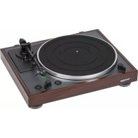
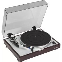
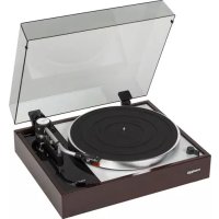
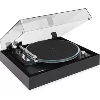
Download the instructions for your Turntable in PDF format for free! Find your manual TP 92 - THORENS and take your electronic device back in hand. On this page are published all the documents necessary for the use of your device. TP 92 by THORENS.
USER MANUAL TP 92 THORENS
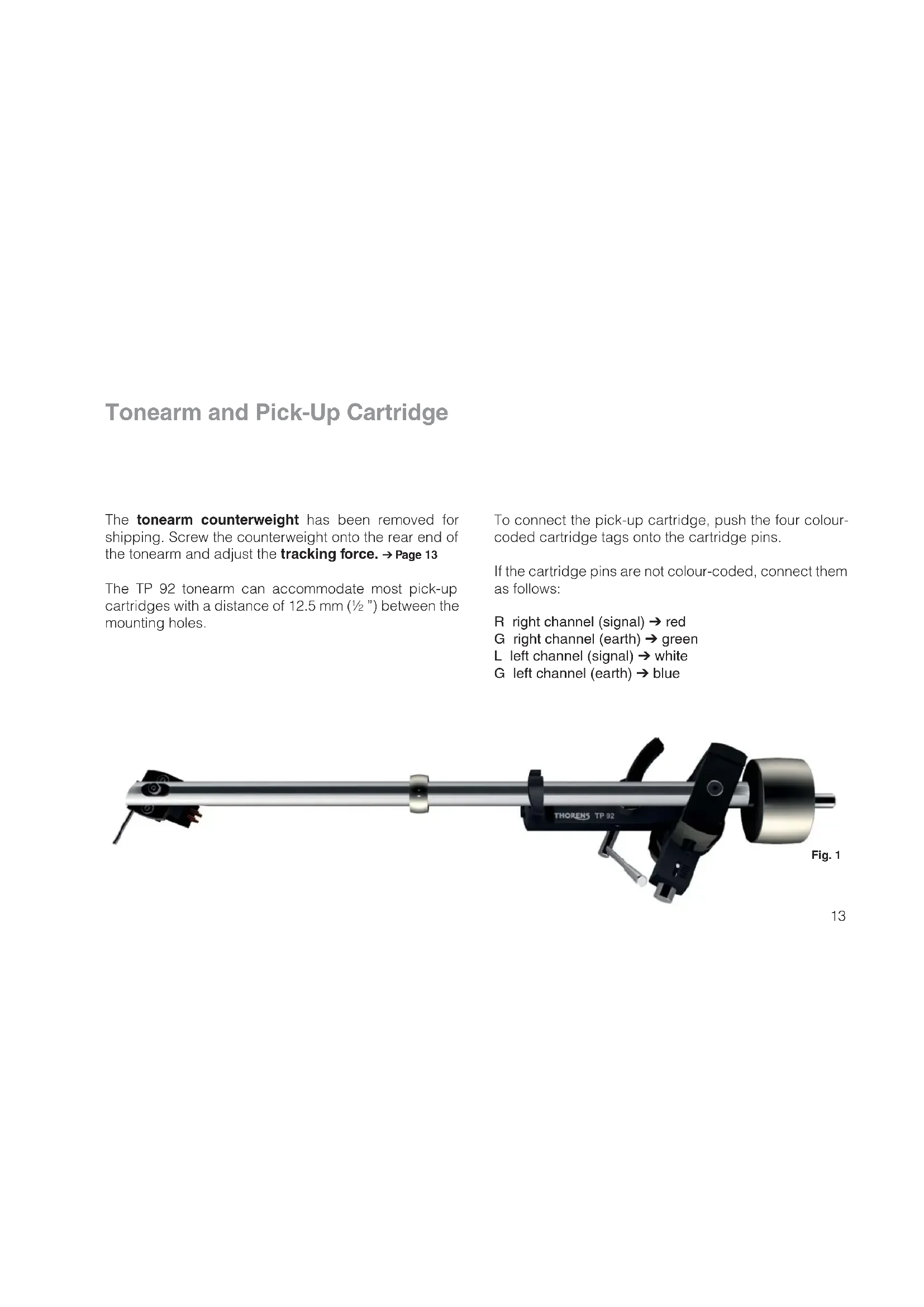
Tonearm and Pick-Up Cartridge
The tonearm counterweight has been removed for shipping. Screw the counterweight onto the rear end of the tonearm and adjust the tracking force. Page 13
The TP 92 tonearm can accommodate most pick-up cartridges with a distance of 12.5mm (1/2^ ) between the mounting holes.
To connect the pick-up cartridge, push the four colour-coded cartridge tags onto the cartridge pins.
If the cartridge pins are not colour-coded, connect them as follows:
R right channel (signal) red
G right channel (earth) green
L left channel (signal) white
G left channel (earth) blue
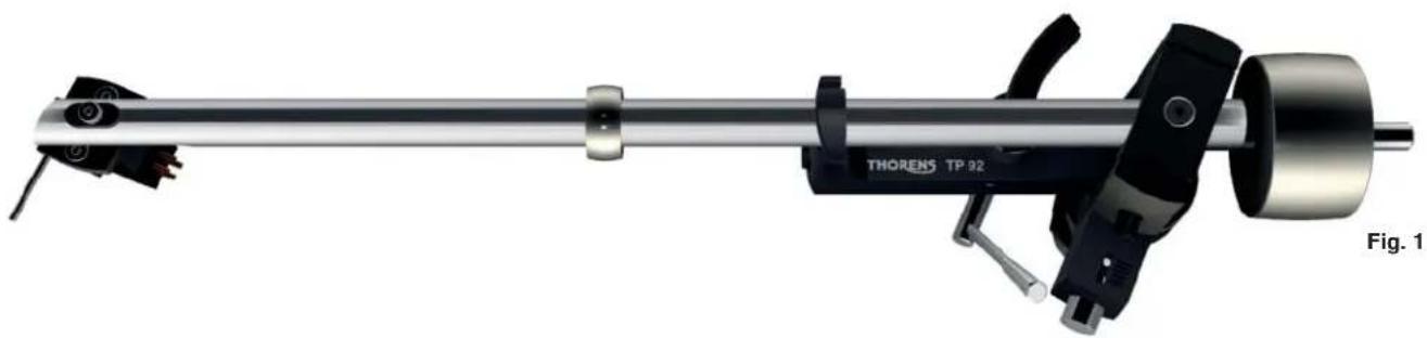
Fig. 1
Tracking Force
The tracking force can be adjusted by rotating the to- neararm counterweight ( Fig.2). The closer the counterweight is to the cartridge, the higher the tracking force.
The tracking force can be set with the help of the supplied stylus balance. Lower the tonearm lift, move the tonearm out over the platter and carefully lower it until the stylus of the pick-up cartridge comes to rest on the stylus balance. The stylus guard must be removed for this procedure.
Great care should be taken to avoid damaging the stylus.
Note: Refer to the user manual of your pick-up cartridge to determine the correct tracking force.
Do not move the ring that sits around the middle of the tonearm tube ( Fig. 1). It serves as a vibration damper and is effective only at its original position.
Anti-Skating Force (Bias)
The interaction of stylus friction and cartridge-bearing forces produces a force which pulls the tonearm towards the centre of the record (referred to as skating force). This force can be offset with the help of anti-skating force, which, in the case of the TP 92, is produced by a magnet incorporated into the tonearm.
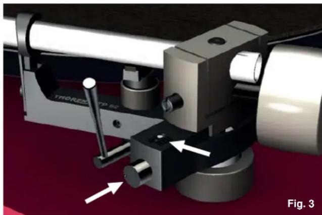
The anti-skating force is factory-adjusted. If necessary, it can be readjusted with the help of an adjustment screw. Fig. 3
Turn the adjustment screw anti-clockwise to increase, and clockwise to decrease the anti-skating force. The white dot above the adjustment screw indicates the setting.
The amount of anti-skating force required depends on the type of pick-up cartridge used. If you change the cartridge for a different type, use a test record to determine how much anti-skating force is required.
Further Tonearm Adjustments
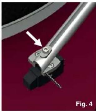
The tonearm headshell allows an overhang adjustment of ± 2,5mm to be made. To adjust overhang, loosen the screw holding the headshell and move the headshell as required. Fig.4
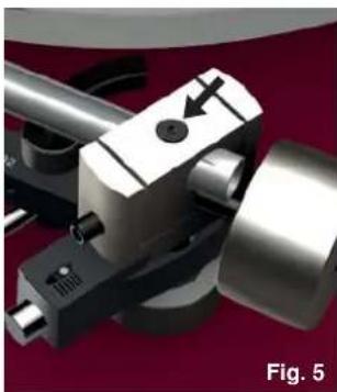
A screw at the rear of the tonearm allows a further overhang adjustment of ± 3mm as well as an azimuth adjustment of ± 5^ . The screw is recessed into the top of the bearing housing and can be loosened with a 2-mm hex key. Fig. 5
The vertical tracking angle (VTA) can be adjusted by raising or lowering the tonearm. Page 16
Take care not to over-tighten the screws after making adjustments.
Further Tonearm Adjustments
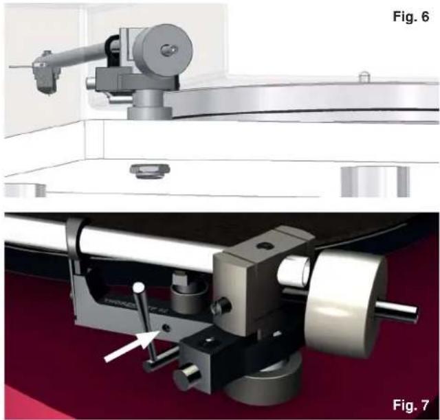
The vertical tracking angle (VTA) can be adjusted by raising or lowering the entire tonearm. Loosen the lock nut ( Fig.6) on the underside of the turntable; then turn the adjustment ring above the base to raise or lower the tonearm as required.
If the VTA is changed, the tonearm lift will need to be to be readjusted. Loosen the locking screw on the tonearm lift with a 1.5-mm hex key and carefully raise or lower the entire lift. Fig.7
The tonearm tube should be parallel to the platter surface. Small adjustments of the VTA or the tonearm lift height can have a large effect. After making any changes, you should therefore always check whether there is enough clearance (at least 1mm ) between the cartridge and the record (when the lift is engaged) and between the tonearm lift pad and the tonearm tube (when the lift is disengaged).
Technical Specifications
TP 92 / 9" TP 92 /10" TP 92 / 12"
| Tonearm specifi cation | 9" | 10" | 12" |
| Distance tonearm pivot to stylus | 215mm | 237,8mm | 291,4mm |
| Effective length | 232,8mm | 254mm | 304,8mm |
| Stylus overhang | 17,8mm | 16,2mm | 17,8mm |
| Angular offset | 23,66° | 21,6° | 17,8° |
| Inner null | 66,0mm | 66,0mm | 66,0mm |
| Outer null | 120,9mm | 120,9mm | 120,9mm |
| Effective mass | 11g | 14g | 21g |
| Maximum distortion between null-points | 0,63% | 0,38% | 0,46% |
| Geometry | Bearwald / Löfgren „A“ | Bearwald / Löfgren „A“ | Bearwald / Löfgren „A“ |
| Weight | 360g | 415g | 465g |
| Connestors | wires for soldering or Mini-Din connectors (OEM Version only) | wires for soldering or Mini-Din connectors (OEM Version only) | wires for soldering or Mini-Din connectors (OEM Version only) |
| Mounting hole | 18mm dia | 18mm dia | 18mm dia |
| Antiskating | ferrite magnets, friction free | ferrite magnets, friction free | ferrite magnets, friction free |
Technical specifications subject to change without notice. Made in Germany.