USER MANUAL MS 24 BIC DE DIETRICH
- Directive gaz 2009/142/CE
- Directive Rendements 92/42/CEE
... CONDUIT D'ASPIRATION ET ÉVACUATION SÉPARÉS
(L) = Phase (marron)
(N) = Neutre (bleu ciel)
+= Terre (jaune-vert)
Figure 13
9912070100
24. VÉRIFICATION DES PARAMÈTRES DE COMBUSTION
Figure 14b
CG_2355_B / 1104_1602
Vidange du ballon
L max = 4 m ( 60/100 mm)
10 m ( 80/125 mm)

L max = 4 m (∅ 60/100 mm)
10 m (∅ 80/125 mm)

L max = 3 m (∅ 60/100 mm)
9 m (∅ 80/125 mm)
L max = 3 m (∅ 60/100 mm)
9 m (∅ 80/125 mm)
0512 2001
16.2 ESEMPI D'INSTALLAZIONE CON CANNE FUMARIE DI TIPO C42
L max = 10 m (∅ 80/125 mm)
L max = 8 m (∅ 80/125 mm)
L max = 9 m (∅ 80/125 mm)
(L1 + L2) max = 30 m
1010 0102/CG1643
B3) Verifiche conclusive
Figura 13
9912070100
24. VERIFICA DEI PARAMETRI DI COMBUSTIONE
Te = temperatura esterna
Grafico 2
27. VASO DI ESPANSIONE SANITARIO (ACCESSORIO A RICHIESTA)
Figura 14
CG_2355_A / 1104_1605
SVUOTAMENTO BOLLITORE
24 BIC
36. CARATTERISTICHE TECNICHE
We are confident your new boiler will meet all your requirements.
All De Dietrich products have been designed to give you what you are looking for: good performance combined with simple and rational use.
Please do not put away this booklet without reading it first as it contains some useful information which will help you to operate your boiler correctly and efficiently.
Do not leave any packaging (plastic bags, polystyrene, etc.) within the reach of children as they are a potential source of danger.
De Dietrich declares that these models of boiler bear the CE mark in compliance with the basic requirements of the following Directives:
- Gas directive 2009/142/EC
- Efficiency Directive 92/42/EEC
- Electromagnetic Compatibility Directive 2004/108/EC
- Low Voltage Directive 2006/95/EC

CONTENTS
INSTRUCTIONS FOR USERS
- Instructions prior to installation 60
- Instructions prior to commissioning 60
- Commissioning the boiler 61
- Adjusting room and DHW temperatures 62
- Description of button (💡) (Summer - Winter - Heating only - Off) 62
- Filling the system 62
- Turning off the boiler 63
- Gas conversion 63
- Prolonged shutdown. Frost protection 63
- Troubleshooting 64
- Routine maintenance instructions 64
INSTRUCTIONS FOR FITTERS
- General information 65
- Instructions prior to installation 66
- Installing the boiler 66
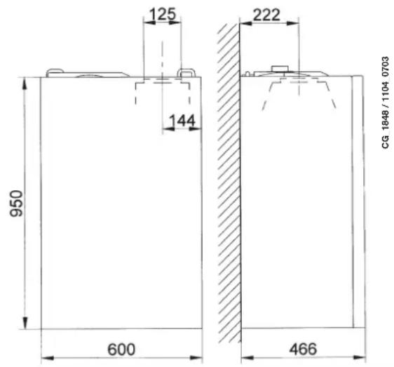
- Dimensions of boiler 68
- Installing the flue and air ducts 68
- Electrical connections 72
- Connecting the room thermostat 72
- Gas conversion 73
- Visualisation of parameters on the display ("info" function) 75
- Parameter settings 76
- Adjustment and safety devices 76
- Positioning the ignition and flame-sensing electrode 78
- Checking combustion parameters 78
- Pump capacity/head 78
- Connecting the external sensor 79
- DHW expansion vessel (available on request) 79
- Annual service 80
- Draining the boiler circuit and the storage boiler 80
- Cleaning the filters 81
- Removing scale from the DHW circuit 81
- Dismounting the water-water heat exchanger 81
- Disassembling the boiler anode 82
- Functional circuit diagram 83
- Wiring diagram 85
- Technical specifications 87
1. INSTRUCTIONS PRIOR TO INSTALLATION
This boiler has been designed to heat water to a temperature lower than boiling point at atmospheric pressure. It must be connected to a central heating system and to a domestic hot water supply system according to its performance and power output.
Before having the boiler installed by a qualified fitter, make sure the following operations are performed:
a) Make sure that the boiler is adjusted to use the type of gas delivered by the gas supply. To do this, check the markings on the packaging and the rating plate on the appliance.
b) Make sure that the flue terminal draft is appropriate, that the terminal is not obstructed and that no exhaust gases from other appliances are expelled through the same flue duct, unless the latter has been specially designed to collect exhaust gas from more than one appliance, in compliance with current laws and regulations.
c) Make sure that, if the boiler is connected to existing flue ducts, these have been thoroughly cleaned as residual products of combustion may detach from the walls during operation and obstruct the flow of fumes.
d) To ensure correct operation and maintain the warranty, observe the following precautions:
1. DHW circuit:
1.1. If the water is harder than 20\ °F ( 1\ °F = 10\ mg calcium carbonate per litre of water), install a polyphosphate dispenser or an equivalent treatment system, compliant with current regulations.
1.2. Thoroughly flush the system after installation of the appliance and before use.
1.3. The materials used for the product's DHW circuit comply with Directive 98/83/CE.
2. Heating circuit
2.1. new system
Before proceeding with installation of the boiler, the system must be cleaned and flushed to eliminate residual thread-cutting swarf, solder and any solvents, using suitable proprietary products. To avoid damaging metal, plastic and rubber parts, only use neutral cleaners, i.e. non-acid and non alkaline. Recommended cleaning products are:
SENTINEL X300 or X400 and FERNOX Regenerator for heating circuits. Use these products in strict compliance with the manufacturers' instructions.
2.2. existing system:
Before installing the boiler, drain the system and clean it to remove sludge and contaminants, using suitable proprietary products as described in section 2.1.
To avoid damaging metal, plastic and rubber parts, use only neutral cleaners, i.e. non-acid and non-alkaline such as SENTINEL X100 and FERNOX Protector for heating circuits. Use these products in strict compliance with the manufacturers' instructions.
Remember that the presence of foreign bodies in the heating system can adversely affect boiler operation (e.g. overheating and excessive noise of the heat exchanger).
Failure to observe the above will render the warranty null and void.
2. INSTRUCTIONS PRIOR TO COMMISSIONING
Initial lighting of the boiler must be carried out by an authorised Service Engineer who must first ensure that:
a) the rated data correspond to the supply (electricity, water and gas) data;
b) the installation complies with current laws and regulations;
c) the appliance is correctly connected to the power supply and earthed. Failure to observe the above will render the guarantee null and void.
Prior to commissioning, remove the protective plastic coating from the boiler. Do not use any tools or abrasive detergents to do this as you may damage the painted surfaces.
The appliance is not intended to be used by persons (including children) with reduced physical, sensory or mental capacities, or who lack experience or knowledge, unless, through the mediation of a person responsible for their safety, they have had the benefit of supervision or of instructions on the use of the appliance.
3. COMMISSIONING THE BOILER
To light the boiler correctly, proceed as follows:
1) power the boiler
2) open the gas tap;
3) press the button (and switch the boiler to Summer (), winter () of heating only ();
4) press the heating circuit (+/-) and domestic hot water circuit (||||) temperature adjustment buttons (≡) in order to ignite the main burner.
When the boiler is lit, the symbol ( ) will appear on the display.
In the Summer position () the main burner will only ignite if a DHW tap is opened.
WARNING
During initial ignition, the burner may not ignite (causing the boiler to shut down) until any air in the gas pipes is vented. In this case, repeat the ignition procedure until gas reaches the burner. Press button R for at least 2 seconds.
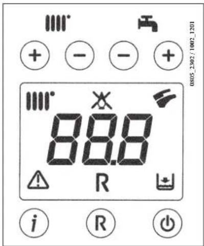
SYMBOL KEY

Operation in the heating mode

Flame present (burner on)

No flame (ignition failure)

Operation in the DHW mode

Generic fault

RESET

No water (Low system pressure)

Numerical signal (Temperature, fault code, etc.)

On / Off / Summer / Winter / heating only

(+/-): CH temperature adjustment

The system must be fitted with a room thermostat for controlling indoor temperature.
Adjust the room temperature ( ) and the DHW temperature ( ) by pressing the respective +/- (figure 1). The ignition of the burner is shown on the display with the symbol ( ) as described in section 3.
HEATING
While the boiler is operating in the heating mode, the display (figure 1) shows the flashing symbol (DH) and the heating delivery temperature (°C).
DOMESTIC HOT WATER
While the boiler is operating in the DHW mode, the display (figure 1) shows the flashing symbol (⚡) and the DHW output temperature (°C).
Press this button to set the following operating modes:
• SUMMER
• WINTER
• HEATING ONLY
• OFF
In the SUMMER mode, the display shows (💡). The boiler satisfies requests for DHW only while central heating is NOT enabled (ambient frost protection function active).
In the WINTER mode, the display shows (###). The boiler satisfies requests for both DHW and central heating (ambient frost protection function active).
In the HEATING ONLY mode, the display shows (____). The boiler satisfies requests for central heating only (ambient frost protection function active).
In the OFF mode, the display shows neither of the above two symbols ( |||| ) ( ▼ ). In this mode, only the ambient frost protection function is active while requests for DHW and central heating are not satisfied.
Disconnect the boiler from the mains power supply using the two-pole switch.
IMPORTANT: Regularly check that the pressure displayed on the pressure gauge is 0.7 - 1.5 bar, with the boiler cold. In case of overpressure, open the boiler drain tap. In case of insufficient temperature, open the boiler filling tap (figure 3). Open the tap very slowly in order to vent the air.
The boiler is fitted with a hydraulic pressure gauge which prevents the boiler from working if there is no water.
N.B.: In case pressure drops occur frequently, have the boiler checked by an authorised Service Engineer.
To turn off the boiler, disconnect the electric power supply. In "OFF" mode (section 5) the boiler remains off (the display indicates OFF) though the electrical circuits remain live and the frost protection device is enabled (section 9).
8. GAS CONVERSION
The boilers can operate both on natural gas and LPG.
All gas conversions must be made by an authorised Service Engineer.
9. PROLONGED SHUTDOWN. FROST PROTECTION
Do not drain the whole system as filling up with water again causes unnecessary and harmful scale to build up inside the boiler and the heating elements. If the boiler is not used during winter and is therefore exposed to the danger of frost, add some specific anti-freeze to the water in the system (e.g.: propylene glycol coupled with corrosion and scale inhibitors). The electronic boiler management system includes a "frost protection" function for the heating system which, when delivery temperature falls below 5°C, operates the burner until a delivery temperature of 30°C is reached.
The frost protection function is enabled if:
* the boiler is electrically powered;
* the gas tap is open;
* the system is at the correct pressure;
* the boiler is not blocked.
10. TROUBLESHOOTING
Faults are shown on the display with an error code (e.g.: E 01):
To RESET the boiler, press and hold down "R" for at least 2 seconds. If this fault persists, call the Authorised Service Centre.
N.B.: 5 reset attempts can be performed after which the boiler shuts down. To reset again, switch off the boiler for a few seconds.
| CODE DISPLAYED | FAULT CORRECTIVE ACTION | |
| E01 Failed | ignition shutdown | Press and hold down “R” for at least 2 seconds. If this fault persists, call the Authorised Service Centre. |
| E02 Safety | thermostat tripped | Press and hold down “R” for at least 2 seconds. If this fault persists, call the Authorised Service Centre. |
| E03 | Flue thermostat/ flue pressure switch tripped | Call the Authorised Service Centre. |
| E04 | Shutdown after 6 consecutive flame losses | Press and hold down “R” for at least 2 seconds. If this fault persists, call the Authorised Service Centre. |
| E05 Flow sensor failure Call the Authorised Service Centre. |
| E06 DHW sensor fault Call the Authorised Service Centre. |
| E10 | Hydraulic pressure switch block | Check that the pressure in the system is correct; See section 6. If this fault persists, call the Authorised Service Centre. |
| E25/E26 | Probable blocked pump safety trip | Call the Authorised Service Centre. |
| E35 Parasite flame (flame error) | Press and hold down “R” for at least 2 seconds. If this fault persists, call the Authorised Service Centre. |
| E96 | Switching off due to reductions in power supply | RESET is automatic. If this fault persists, call the Authorised Service Centre |
N.B.: in case of a fault, the display backlighting flashes together with the error code.
11. ROUTINE MAINTENANCE INSTRUCTIONS
To keep the boiler efficient and safe, have it checked by the authorised Service Centre at the end of every operating period. Careful servicing ensures economical operation of the system.
Do not clean the outer casing of the appliance with abrasive, aggressive and/or easily flammable cleaners (e.g.: petrol, alcohol, and so on). Always switch off the appliance before cleaning it (see section 7 Switching off the boiler).
The following notes and instructions are addressed to fitters to allow them to carry out trouble-free installation. Instructions for igniting and using the boiler are contained in the ‘Instructions for Users’ section.
- This boiler can be connected to any type of double- or single-pipe convector plate, radiator or thermoconvector. Design the system sections as usual, though, bearing in mind the available flow-head at the plate, as shown in section 25.
- Do not leave any packaging (plastic bags, polystyrene, etc.) within reach of children, as it is a potential source of danger.
- Initial lighting of the boiler must be carried out by an authorised Service Engineer, as indicated on the attached sheet. Failure to observe the above will render the guarantee null and void.
ADDITIONAL PUMP WARNING
If an additional pump is used on the heating system, position it on the boiler return circuit. This will allow the correct operation of the water pressure switch.
SOLAR WARNING
if the instantaneous (mixed) boiler is connected to a system with solar panels, the maximum temperature of the domestic hot water entering the boiler must not exceed 60° C.
13. INSTRUCTIONS PRIOR TO INSTALLATION
This boiler has been designed to heat water to a temperature lower than boiling point at atmospheric pressure. It must be connected to a central heating system and to a domestic hot water supply system according to its performance and power output.
Do the following before connecting the boiler:
a) Make sure that the boiler is adjusted to use the type of gas delivered by the gas supply. To do this, check the markings on the packaging and the rating plate on the appliance.
b) Make sure that the flue terminal draft is appropriate, that the terminal is not obstructed and that no exhaust gases from other appliances are expelled through the same flue duct, unless the latter has been specially designed to collect exhaust gas from more than one appliance, in compliance with current laws and regulations.
c) Make sure that, if the boiler is connected to existing flue ducts, these have been thoroughly cleaned as residual products of combustion may detach from the walls during operation and obstruct the flow of fumes.
To ensure correct operation and maintain the warranty, observe the following precautions:
1. DHW circuit:
1.1. If the water is harder than 20\ °F ( 1\ °F = 10\ mg\ calcium\ carbonate\ per\ litre\ of\ water ), install a polyphosphate dispenser or an equivalent treatment system, compliant with current regulations.
1.2. Thoroughly flush the system after installation of the appliance and before use.
1.3. The materials used for the product's DHW circuit comply with Directive 98/83/CE.
2. Heating circuit
2.1. new system
Before proceeding with installation of the boiler, the system must be cleaned and flushed to eliminate residual thread-cutting swarf, solder and any solvents, using suitable proprietary products. To avoid damaging metal, plastic and rubber parts, only use neutral cleaners, i.e. non-acid and non alkaline. Recommended cleaning products are: SENTINEL X300 or X400 and FERNOX Regenerator for heating circuits. Use these products in strict compliance with the manufacturers' instructions.
2.2. existing system:
Before installing the boiler, drain the system and clean it to remove sludge and contaminants, using suitable proprietary products as described in section 2.1.
To avoid damaging metal, plastic and rubber parts, use only neutral cleaners, i.e. non-acid and non-alkaline such as SENTINEL X100 and FERNOX Protector for heating circuits. Use these products in strict compliance with the manufacturers' instructions.
Remember that the presence of foreign bodies in the heating system can adversely affect boiler operation (e.g. overheating and excessive noise of the heat exchanger).
Failure to observe the above will render the warranty null and void.
14. INSTALLING
After deciding the exact location of the boiler, make sure there is sufficient room to perform maintenance operations (at least 450 mm of headroom is required in order to replace the expansion vessel).
Connect the system to the gas and water inlets present on the lower bar of the template. Fit two G3/4 taps (flow and return) on the central heating circuit; these taps make it possible to carry out important operations on the system without draining it completely. If you are either installing the boiler on an existing system or replacing one, as well as the above, fit a settling tank under the boiler on the system return line in order to collect any deposits and scale circulating in the system after flushing. After fixing the boiler to the template, connect the flue and air ducts, supplied as accessories, as described in the following sections.
If the model 24 BIC natural draught boiler is installed, connected it to the flue with a metal pipe resistant to normal mechanical stress, heat, products of combustion and relative condensate.
IMPORTANT
After filling the boiler, vent the entire internal circuit and the system as follows:
- close the gas on-off valve;
• power the boiler.
- open the vent valve on the pump body;
- press ( ) to set the boiler in the "WINTER" operating mode;
- send a heat demand from the room thermostat;
- open a hot water tap to alternate CH demand with DHW demand;
• after a few ignition attempts the boiler will shut down (error E01 appears on the display);
- to rest, press and hold down "R" for at least 2 seconds;
- repeat the procedure at least another two times;
- close the vent valve.
After venting the boiler circuit, proceed with initial lighting.
EXPANSION VESSEL
The boiler features a standard 7.5-litre expansion vessel with a pre-charge pressure of 1 bar. The maximum volume of water in the system is calculated according to hydrostatic pressure at an average water temperature of 80°C (flow: 95°C return: 75°C ).
| Hydrostatic pressure (m) 5 6 7 8 9 10 | | | | | |
| Maximum system volume (l) 138 131 119 | 107 97 87 | | | | |
Figure 4
WARNING
Tighten the boiler nipple water connections with care (maximum tightening torque 30 Nm).
| G”3/4 HEATING FLOW G”1/2 DOMESTIC HOT WATER OUTLET | | |
| G”3/4 HEATING RETURN G”1/2 DOMESTIC COLD WATER INLET | | |
| G”3/4 GAS INLET TO BOILER | | |
24 BIC FF 24 BIC
16. INSTALLING THE FLUE AND AIR DUCTS
Model 24 BIC FF
The boiler is easy and flexible to install thanks to the extensive range of available accessories, as described below.
The boiler has been designed for connection to a vertical or horizontal coaxial flue-air duct. A splitting kit is also available if separate ducts are required.
Only accessories supplied by the manufacturer must be used for installation!
WARNING: To optimise operating safety, make sure the flue ducts are firmly fixed to the wall with suitable brackets.
... COAXIAL FLUE-AIR DUCT (CONCENTRIC)
This type of duct is used to discharge exhaust fumes and draw combustion air both outside the building and if a LAS flue is fitted.
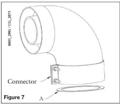
The 90° coaxial curve allows the boiler to be connected to a flue-air duct in any direction as it can be rotated by 360° . It can also be used as a supplementary curve combined with a coaxial duct or a 45° curve.
If fumes are discharged outside the building, the flue-air duct must protrude at least 18 mm from the wall to allow an aluminium weathering surround to be fitted and sealed to avoid water infiltrations.
Make sure there is a minimum upward slope towards the outside of 1 cm per metre of duct.
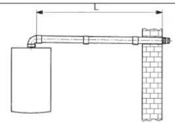
- A 90° curve reduces total duct length by 1 metre.
- A 45° curve reduces total duct length by 0.5 metres.
The first 90° curve is not considered when calculating the maximum available length.
| Diameter coaxial flue-air duct (mm) Lenght (m) | Use of DIAPHRAGM on INLET LINE A (mm) |
| 60/100 | 0 ÷ 1,5 76 | |
| 1,5 ÷ 4 NO | |
| 80/125 | 0 ÷ 5 80 | |
| 5 ÷ 10 NO | |
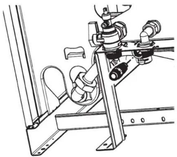
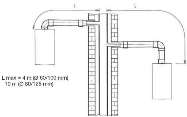
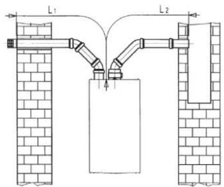
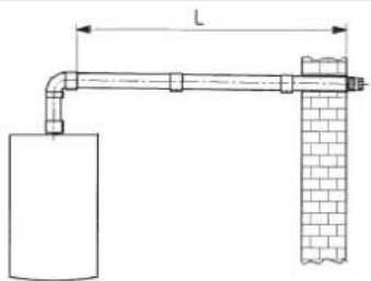
16.1 HORIZONTAL FLUE INSTALLATION EXAMPLES
L max = 4 m ( 60/100 mm)
10 m ( 80/125 mm)
L max = 4 m ( 60/100 mm)
10 m ( 80/125 mm)
L max = 3 m (∅ 60/100 mm)
9 m (∅ 80/125 mm)

L max = 3 m (∅ 60/100 mm)
9 m (∅ 80/125 mm)
0512 2001
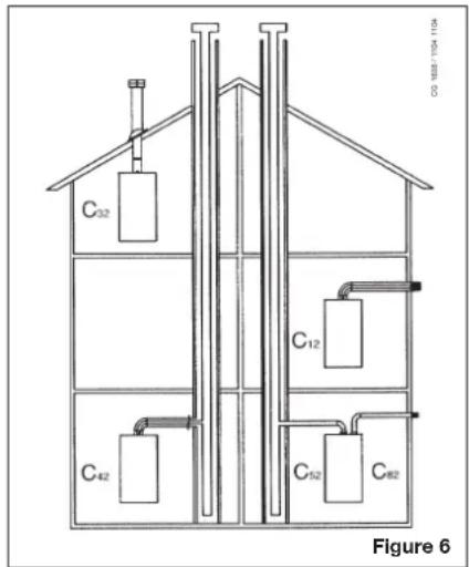
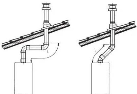
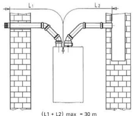
16.2 LAS FLUE DUCT INSTALLATION EXAMPLES C42 TYPE
0503-0907/C41640

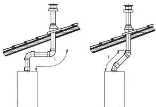
16.3 VERTICAL FLUE INSTALLATION EXAMPLES
This type of installation can be carried out on either a flat or a pitched roof by fitting a flue terminal and a special weathering surround with sleeve (both available on request).
0503-0908/CQ1641
L max = 10 m (∅ 80/125 mm)

L max = 8 m (∅ 80/125 mm)
L max = 9 m (∅ 80/125 mm)
For detailed installation instructions, consult the technical data provided with the accessories.
... SEPARATE FLUE AND AIR DUCTS
This type of installation makes it possible to discharge exhaust fumes both outside the building and into single flue ducts. Comburent air can be drawn in at a different location from that of the flue terminal. The splitting kit comprises a flue duct adaptor (100/80) and an air duct adaptor. For the air duct adaptor, fit the screws and seals previously removed from the cap.
| Boiler model (L1+L2) | | Position of air regulator | CO2 % |
| G20 G31 | |
| 24 BIC FF | 0÷20 1 | | 6,1 8,7 | |
| 20÷30 2 | |
The first 90° curve is not considered when calculating the maximum available length.
The 90° curve allows the boiler to be connected to a flue-air duct in any direction as it can be rotated by 360° . It can also be used as a supplementary curve combined with a duct or a 45° curve.
- A 90° curve reduces total duct length by 0.5 metres.
- A 45° curve reduces total duct length by 0.25 metres.
Adjusting the air regulator for separate flues
This regulator must be adjusted to optimise combustion efficiency and parameters.
After turning the air intake connector, which can be mounted both to the right and the left of the exhaust flue duct, suitably adjust the excess air according to the total length of the combustion exhaust and inlet flue ducts.
Turn this regulator anticlockwise to decrease the excess of comburent air and vice-versa to increase it.
To fine tune, use a combustion product analyser to measure the amount of CO2 in the fumes at maximum heat capacity, and, if a lower value is measured, gradually adjust the air regulator until the amount of CO2 indicated in the following table is measured.
To mount this device correctly, consult the relative instructions.
16.4 DIMENSIONS OF SEPARATE OUTLETS
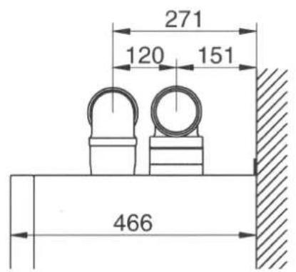
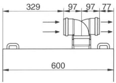
CG_2344 / 1103_3002
16.5 HORIZONTAL SEPARATE FLUE INSTALLATION EXAMPLES - C82
IMPORTANT - Make sure there is a minimum downward slope towards the outside of 1 cm per metre of duct length. In the event of installation of the condensate collection kit, the angle of the drain duct must be directed towards the boiler.
CG_1643_FR / 1010_0101
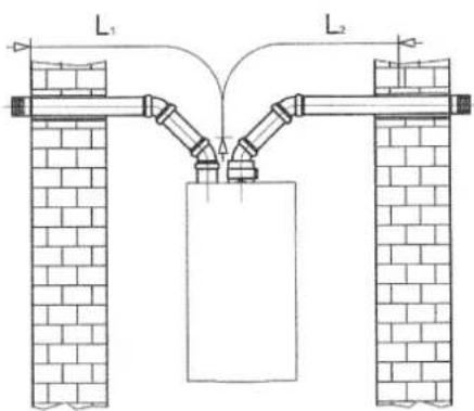
L max = 10 m
(L1 + L2) max = 30 m
1010_0102/CG1643
N.B.: For the C52 type, do not fit the flue and air duct terminals on opposite walls of the building. The inlet flue must have a maximum length of 10 metres for C52 fumes outlets.
If the discharge duct is longer than 6 metres, install the condensate collection kit, supplied as an accessory, near the boiler
IMPORTANT: if fitting a single flue duct, make sure it is adequately insulated (e.g.: with glass wool) wherever the duct passes through building walls. For detailed installation instructions, consult the technical data provided with the accessories.
17. ELECTRICAL CONNECTIONS
This machine is only electrically safe if it is correctly connected to an efficient earth system in compliance with current safety regulations.
Connect the boiler to a 230V single-phase earthed power supply using the supplied three-pin cable, observing correct LIVE-NEUTRAL polarity.
Use a double-pole switch with a contact separation of at least 3 mm. When replacing the power supply cable, fit a harmonised HAR H05 VV-F' 3x0.75mm 2 cable with a maximum diameter of 8 mm.
...Access to the power supply terminal block
- disconnect the boiler from the mains power supply using the two-pole switch;
- remove the two screws fixing the control panel to the boiler;
- rotate the control panel;
- remove the cover and access the wiring area (figure 9).
The 2A fast-blowing fuse is incorporated in the power supply terminal block (to check and/or replace the fuse, pull out the black fuse carrier).
IMPORTANT: respect polarity L (LIVE) -N (NEUTRAL).
(L) = Live (brown)
(N) = Neutral (blue)
Earth (yellow-green)
(1) (2) = Contact for room thermostat
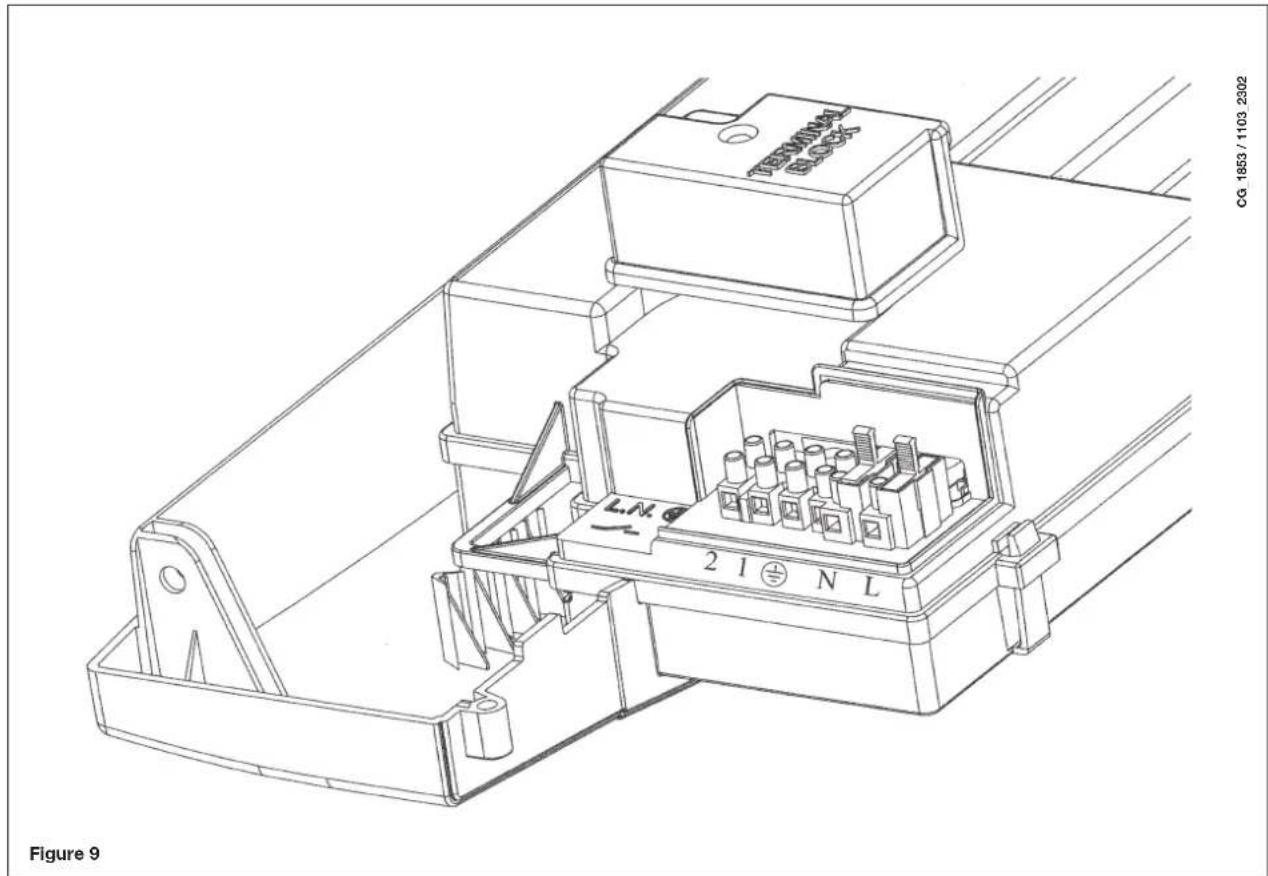
18. CONNECTING THE ROOM THERMOSTAT
- Access the power supply terminal block (figure 9) as described in the previous section;
- remove the jumper on terminals (1) and (2);
- thread the two-wire cable through the grommet and connect it to these two terminals.
19. GAS CONVERSION
The authorised Technical Assistance Service can convert this boiler to natural gas (G. 20) or liquid gas (G.31).
Carry out the following operations:
A) replace the nozzles of the main burner and the gas diaphragm (if fitted);
B) new max. and min. calibration of the pressure regulator.
A) Replace the burner nozzles
• carefully pull the main burner off its seat;
- replace the main burner nozzles making sure to fully tighten them to prevent gas leaks. Nozzle diameters are specified in table 2.
- replace the gas membrane located on the gas valve (figure 10). The diameter of the membrane is specified in table 2. Attention: it is not necessary to change parameter F02.
B) Calibrate the pressure regulator
- connect the positive pressure test point of a differential pressure gauge (possibly water-operated) to the gas valve pressure test point (Pb) (Figure 10). Only for models with sealed chambers, connect the negative pressure test point of the manometer to a "T" fitting in order to join the boiler adjustment outlet, the gas valve adjusting outlet (Pc) and the pressure gauge. (The same measurement can be made by connecting the pressure gauge to the pressure test point (Pb) after removing the front panel of the sealed chamber);
Measuring burner pressure using methods other than those described could lead to incorrect results as the low pressure created by the fan in the sealed chamber would not be taken into account.
B1) Adjustment to nominal heat output:
- open the gas tap and switch the boiler to the Winter mode;
• take the boiler to maximum power as described in section 19.1;
- remove the modulator cover;
- adjust the tube brass screw (a) until the pressure values shown in table 1 are obtained;
- make sure that the dynamic inlet pressure of the boiler, measured at the gas valve pressure test point (Pa) (Figure 10) is correct (37 mbar for propane or 20 mbar for natural gas).
B2) Adjustment to reduced heat output:
- disconnect the modulator power cable and unscrew the screw (b) until a pressure value corresponding to reduced heat output is achieved (see tab. 1);
- reconnect the cable;
- mount the modulator cover and seal.
B3) Final checks
- attach the additional plate supplied with the transformer, specifying the type of gas and the calibration performed.
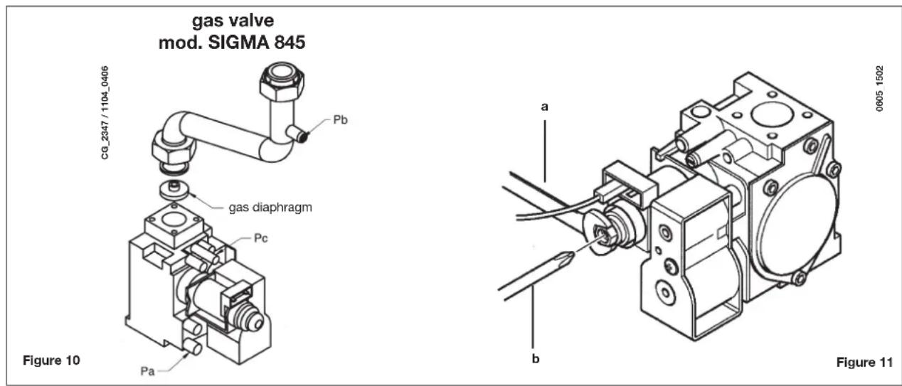
ATTENTION
If the natural gas inlet pressure is too low (less than 17 mbar) remove the gas diaphragm installed over the gas valve (fig. 10) and set parameter F02=00 on the electronic board ( 21 ).
19.1 GAS VALVE CALIBRATION FUNCTION
To simplify calibration of the gas valve, the calibration function may be set directly on the boiler control panel as follows:
a) hold down the buttons and together for at least 6 seconds;
b) after about 6 seconds, the symbols mark;
c) the display shows, at intervals of one second, "100" and the flow temperature. In this phase, the boiler works at the maximum heating output (100%).
d) press +/- to immediately set the power of the boiler (100% or 0%);
e) adjust the "Pmax/Pmin" screw (figure 10) to set the burner pressure value as described in table 1.
To adjust pressure at maximum power, turn the "Pmax" screw (fig. 10) clockwise to increase or anti-clockwise to decrease pressure at the burner.
To adjust pressure at minimum power, turn the "Pmin" screw (fig. 10) clockwise to increase or anti-clockwise to decrease pressure at the burner.
f) press +/- ### to gradually set the desired power level (interval = 1%).
Press the button ⏻ to leave the function.
Note:
The function is automatically deactivated after a period of 15 minutes, at the end of which the electronic board returns to its operating status prior to the activation of the function or prior to reaching the set maximum temperature.
Table of burner nozzles
| 24 BIC FF | 24 BIC |
| gas type | G20 | G31 | G20 | G31 |
| diameter of nozzles (mm) | 1,18 | 0,69 | 1,18 | 0,69 |
| Burner pressure (mbar*) REDUCED HEAT OUTPUT | 1,7 | 6,9 | 1,6 | 6,6 |
| Burner pressure (mbar*) RATED HEAT OUTPUT | 7,8 | 24,7 | 7,5 | 18,1 |
| Diameter of gas diaphragm (mm) | 4,2 | 3,5 | 4,2 | 3,5 |
| N° nozzles | 18 |
Table 1
| Consumption 15°C-1013 mbar | 24 BIC FF - 24 BIC |
| G20 | G31 |
| Rated power | 2,73 m3/h | 2,00 kg/h |
| Reduced power | 1,26 m3/h | 0,92 kg/h |
| p.c.i. | 34,02 MJ/ m3 | 46,34 MJ/kg |
Table 2
* 1 mbar = 10,197 mmH₂O
20. VISUALISATION OF PARAMETERS ON THE DISPLAY ("INFO" FUNCTION)
Press “i” for at least 5 seconds to visualise certain boiler information on the display on the front panel of the boiler.
N.B: when the "INFO" function is enabled, the message "A00", alternating with the boiler delivery temperature, is shown on the display (figure 12):
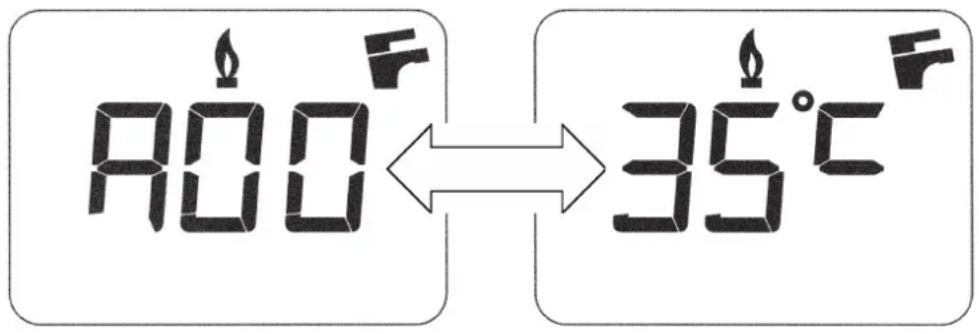
0605-2204/CG-1808
Figure 12
- Press buttons (✗/-) to display the following information:
A01: current external temperature (°C) (with external sensor connected);
A02: modulation current value (100% = 310 mA);
A03: power range (%) (MAX R);
A04: heating setpoint temperature (°C) -- If the external sensor is connected, the value of the "kt" curve is displayed (section 26);
A05: current heating delivery temperature (°C);
A09: last error that occurred in the boiler.
- This function remains active for 3 minutes. It is possible to interrupt the "INFO" function in advance by pressing button (i) for at least 5 seconds, or turning off the power to the boiler.
21. PARAMETER SETTINGS
To set the boiler parameters, press (−) and (−) together and hold down for at least 6 seconds. When the function is activate, the “F01” appears on the display alternating with the value of the parameter shown.
Edit parameters
- Press (+/-) to scroll through the parameters;
- Press (+/-) to edit each parameter;
- Press (⏻), to save the changes. "MEM" appears on the display;
- Press (i), to exit without saving. "ESC" appears on the display.
| Description of parameters | Factory settings |
| 24 BIC FF 24 BIC |
| F01 | Type of boiler10 = sealed chamber 20 = atmospheric chamber | 10 20 | |
| F02 | Gas used00 = METHANE01 = LPG02 = METHANE (WITH DIAPHRAGM) | 02 |
| F03 | Hydraulic system 15 | |
| F04 | Setting programmable relay 1 (See SERVICE instructions)00 = no associated function01 = condominium alarm02 = ambient fan03 = not used04 = zone pump controlled by room thermostat (230V)05 = not used | 04 |
| F05 | Setting programmable relay 2 (DHW pump) | 03 |
| F06 | Maximum CH setpoint (°C)00 = 85°C - 01 = 45°C (function unavailable) | 00 |
| F07 | DHW inlet priority configuration | 00 |
| F08 | CH max. output (0-100%) | 100 |
| F09 | DHW max. output (0-100%) | 100 |
| F10 | Min. heating output (0-100%) | 00 |
| F11 | Delay prior to new ignition in CH mode(00-10 minutes) - 00=10 seconds | 03 |
| F12 | Diagnostics (See SERVICE Instructions) | -- |
| F13-F14-F15 | Factory settings (no change) 00 | |
| F16 | Anti-legionella function00 = disabled55...67 = enabled (setpoint °C) | 00 |
| F17 | CH pressure sensor selection00 = hydraulic pressure sensor01 = hydraulic differential pressure sensor | 00 |
| F18 | Manufacture information | 00 |
22. ADJUSTMENT AND SAFETY DEVICES
The boiler has been designed in full compliance with European reference standards and in particular is fitted with the following:
• Air pressure switch (model 24 BIC FF)
This device only allows the burner to ignite if the exhaust flue duct is in perfect working order.
In the event of one or more of the following faults:
- flue terminal obstructed
• venturi tubes obstructed
- fan blocked
- venturi tube connection - pressure switch tripped
the boiler remains on standby and error code E03 is displayed (see table in section 10).
• Fumes thermostat (model 24 BIC)
This device has a sensor positioned on the left section of the fumes hood and shuts off the gas flow to the main burner if the flue is obstructed and/or if there is no draught.
In these conditions the boiler shuts down and displays error code E03 (section 10).
After eliminating the problem, press button ( ) for at least 2 seconds to re-ignite immediately.
It is forbidden to disable this safety device
- Safety thermostat
Thanks to a sensor placed on the CH flow line, this thermostat interrupts the flow of gas to the burner if the water in the primary circuit overheats. In these conditions, the boiler is blocked and only after the fault has been eliminated can it be ignited again by pressing (R) for at least 2 seconds.
It is forbidden to disenable this safety device
- Flame ionization detector
The flame sensing electrode, located on the right-hand side of the burner, guarantees safety of operation in case of gas failure or incomplete ignition of the burner.
In these conditions, the boiler is blocked after 3 ignition attempts.
Press ( ). For at least 2 seconds to re-establish normal operating conditions.
• Hydraulic pressure switch
This device allows the main burner to be ignited only if system pressure is higher than 0.5 bars.
- Pump overrun for heating circuit
The electronically-controlled pump post-circulation function lasts 180 seconds and is enabled, in the heating mode, if the ambient thermostat causes the burner to go out.
The electronically-controlled pump post-circulation function lasts 30 seconds and is enabled, in the DHW mode, if the probe causes the burner to go out.
- Frost protection device (CH and DHW systems)
The electronic boiler management system includes a “frost protection” function for the heating system which, when delivery temperature falls below 5° C, operates the burner until a delivery temperature of 30° C is reached.
This function is enabled when the boiler is switched on, the gas supply is open and the system is correctly pressurised.
• Water not circulating in primary circuit (pump probably blocked)
If there is insufficient or no water circulating in the primary circuit, the boiler blocks and the error code E25 is shown on the display (section 10).
• Anti-block pump function
If no heat demand is received for 24 consecutive hours, in the heating mode, the pump will automatically start and operate for 10 seconds. This function is operative when the boiler is powered.
- Three-way valve anti-blockage function
If no heat demand is received for a period of 24 hours, the three-way valve performs a complete switching cycle. This function is operative when the boiler is powered.
• Hydraulic safety valve (heating circuit)
This device is set to 3 bar and is used for the heating circuit.
Connect the safety valve to a drain trap. Do not use it to drain the heating circuit.
N.B.: domestic hot water is guaranteed even if the NTC sensor develops a fault. In this case, temperature is controlled by the delivery sensor.
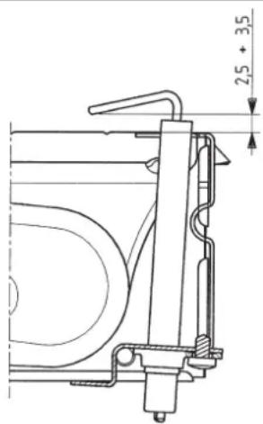
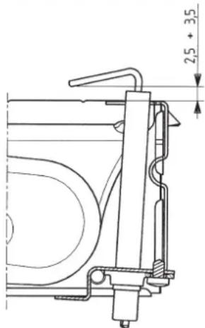
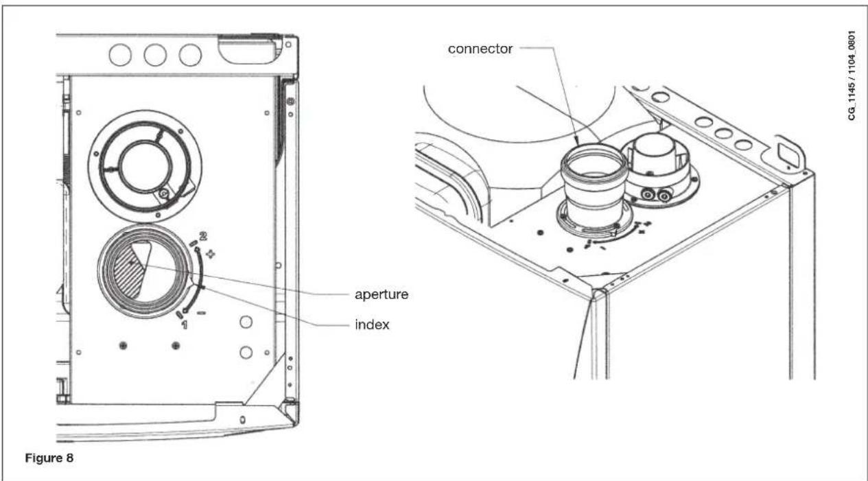
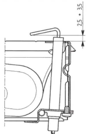
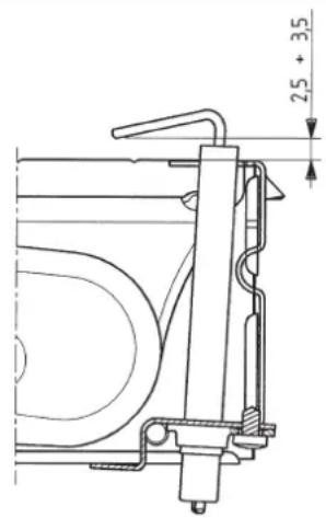
23. POSITIONING THE IGNITION AND FLAME-SENSING ELECTRODE
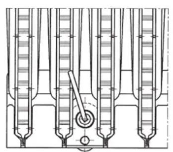
Figure 13

9912070100
24. CHECKING COMBUSTION PARAMETERS
To measure combustion efficiency and the toxicity of the products of combustion, the boiler is fitted with two dedicated test points.
One connection point is connected to the exhaust duct and is used to measure combustion efficiency and the toxicity of the products of combustion.
The other is connected to the air intake circuit and is used to check for the presence of any products of combustion circu-lating in installations with co-axial flues.
The following parameters can be measured using the test point connected to the exhaust duct:
• temperature of the products of combustion;
• concentration of oxygen ( O2 ) or, alternatively, carbon dioxide ( CO2 );
• concentration of carbon monoxide (CO).
The temperature of the comburent air must be measured on the test point located on the air intake flue by inserting the measurement sensor by about 3 cm.
N.B.: to regulate the rated power, see chapter 19 (B1)
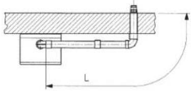
For natural draught boiler models, a hole must be made in the exhaust flue at a distance from the boiler equal to twice the internal diameter of the flue.
The following parameters can be measured through this hole:
• temperature of the products of combustion;
• concentration of oxygen ( O2 ) or, alternatively, carbon dioxide ( CO2 );
• concentration of carbon monoxide (CO).
The temperature of the combustion air must be measured close to the point where the air enters the boiler. The hole, which must be made by the person in charge of the system during commissioning, must be sealed so as to ensure that the exhaust duct is airtight during normal operation.
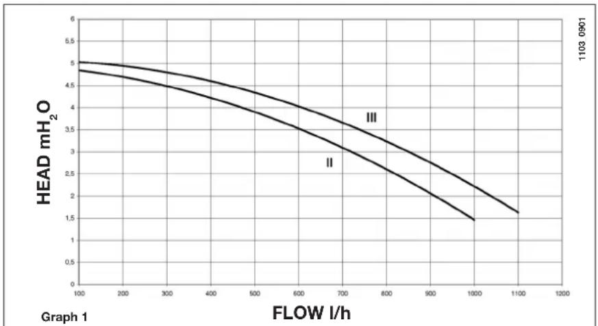
25. PUMP CAPACITY/ HEAD
A high static head pump (GRUN-DFOS UPSO 15-50), suitable for installation on any type of single- or double-pipe heating system, is used. The automatic air valve incorporated in the pump allows quick venting of the heating system.
26. CONNECTING THE EXTERNAL SENSOR
The wiring harness leaving the control board includes two RED wires fitted with faston covers. Connect the external sensor to these two wires.
With the external sensor connected, the "kt" curve (Graph 2) can be changed by pressing +/-
N.B.: In case of installation in an average living unit (good perimeter insulation and radiator systems), set the "kt" climate curve to "25".
"kt" curves
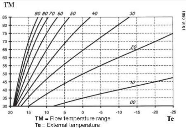
Graph 2
27. DHW EXPANSION VESSEL (AVAILABLE ON REQUEST)
DHW expansion vessel kit comprising:
- 1 stainless steel expansion vessel;
- 1 support for expansion vessel;
- 1 nipple G1/2";
- 1 lock nut;
- 1 connection hose.

Connect the hose (supplied as an accessory in the expansion vessel kit) to the two connectors A and B as shown in figure. The DHW expansion vessel should be mounted if:
- the pressure of the water supply or lifting system is such as to require the installation of a pressure reducer (pressure higher than 4 bar)
- a non-return valve is fitted to the water supply line
- the water supply network is insufficient for the expansion of the water contained in the storage boiler and it is necessary to use the DHW expansion vessel.
TIPS
For the efficient operation of the expansion vessel, the pressure of the water supply must be lower than 4 bar. If it is not, install a pressure reducer. Adjust the pressure reducer to obtain a water supply pressure less than 4 bar.
28. ANNUAL SERVICE
To optimise boiler efficiency, carry out the following annual controls:
- check the appearance and air-tightness of the gaskets of the gas and combustion circuits;
- check the state and correct position of the ignition and flame-sensing electrodes;
- check the state of the burner and make sure it is firmly fixed;
- check for any impurities inside the combustion chamber.
Use a vacuum cleaner to do this;
- check the gas valve is correctly calibrated;
- check the pressure of the heating system;
- check the pressure of the expansion vessel;
- check the fan works correctly;
• make sure the flue and air ducts are unobstructed.
- check the state of the boiler anode.
WARNINGS
Before commencing any maintenance operations, make sure the boiler is disconnected from the power supply. Afterwards, move the knobs and/or operating parameters of the boiler to their original positions.
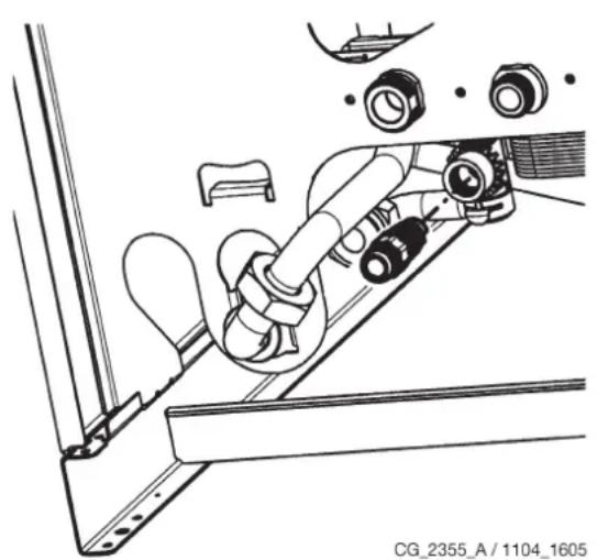
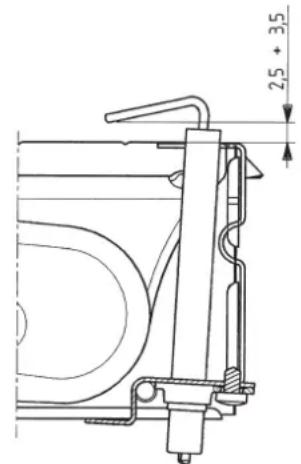
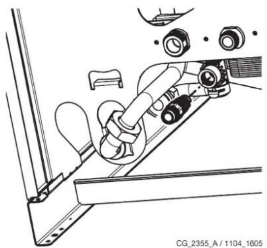
29. DRAINING THE BOILER CIRCUIT AND THE STORAGE BOILER
Drain the boiler by opening the tap in the hydraulic assembly.
To drain the boiler using the drain tap located at the bottom, proceed as follows (fig. 14):
- close the boiler on/off valves;
- open the drain tap using an 8 mm hex wrench;
- drain the boiler;
- close the drain tap using the 8 mm hex wrench.
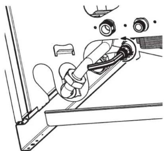
Figure 14
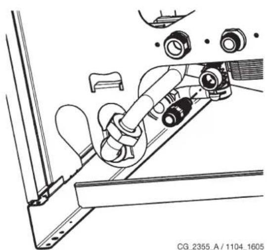
CG_2355_A / 1104_1605
Drain the water in the storage boiler as follows:
- close the water inlet tap;
- open a user tap;
- open the relative drain tap (Fig. 2-B);
- loosen the nut on the DHW outlet pipe at the bottom of the storage boiler.
30. CLEANING THE FILTERS
The DHW and CH filters are housed in special extractable cartridges. The CH cartridge is located on the CH return line (figure 15F). To clean the filters, proceed as described below:
- switch off the boiler;
- shut the DHW inlet tap
- drain the water in the CH circuit by opening tap A in figure 15.
- remove the clip (1-F) from the filter as illustrated in the figure and take out the cartridge (2-F) containing the filter, taking care not to apply excessive force;
• to extract the heating filter cartridge, first remove the 3-way valve motor (1-2G - figure 15);
• eliminate any impurities and deposits from the filter;
- reposition the filter in the cartridge and put it back into its housing, securing it with the clip.
WARNING
when replacing and/or cleaning the O-rings on the hydraulic assembly, only use Molykote 111 as a lubricant, not oil or grease.
31. REMOVING SCALE FROM THE DHW CIRCUIT
To clean, proceed as follows:
• Turn off the DHW inlet tap
- Drain the DHW system by opening a hot water tap
• Turn off the DHW outlet tap
- Remove the clip 1E in figure 15.
- Remove the filter (2E figure 15).
Dismount the water-water heat exchanger, as described in the next section, and clean it separately. To clean the exchanger and/or DHW circuit, use Cillit FFW-AL or Benckiser HF-AL.
32. DISMOUNTING THE WATER-WATER HEAT EXCHANGER
The stainless steel plate-type water-water heat exchanger can be easily disassembled with an M4 spanner by operating as described below:
- drain the system, just the boiler if possible, through the drain tap;
- drain the DHW system;
- remove the two screws at the front securing the water-water heat exchanger and pull it out (figure 15B).
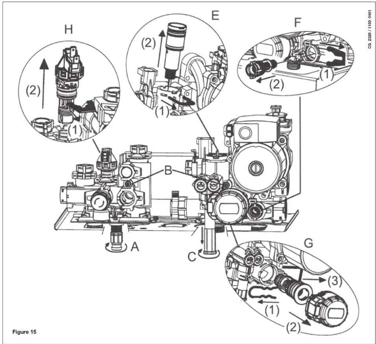
WARNING
Pay great attention when dismantling the individual parts of the hydraulic assembly. Do not use sharp tools, do not apply excessive force when removing the fixing clip.
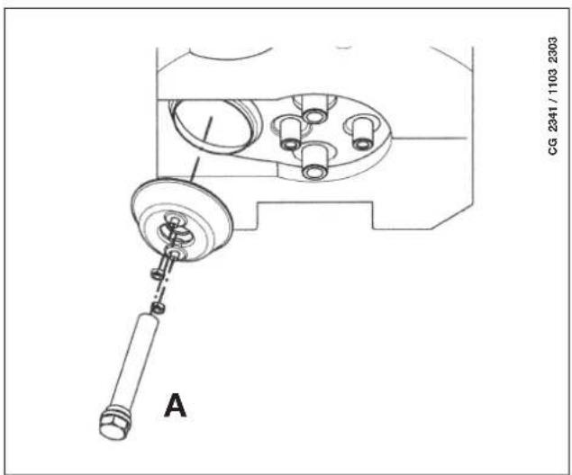
33. DISASSEMBLING THE BOILER ANODE
Check the state of the protective magnesium anode on an annual basis
(before proceeding, empty the boiler circuit using the relevant drain tap).
To disassemble the anode unit remove the boiler sensor fixing clip, take it out and with a 27mm spanner (A) and loosen the anode support nut.
34. FUNCTIONAL CIRCUIT DIAGRAM
24 BIC FF
![graph TD A["outlet"] --> B["DHW inlet"] B --> C["21"] C --> D["15"] D --> E["M"] E --> F["13"] F --> G["12"] G --> H["11"] H --> I["10"] I --> J["9"] J --> K["8"] K --> L["7"] L --> M["6"] M --> N["5"] N --> O["4"] O --> P["3"] P --> Q["2"] Q --> R["1"] R --> S["Gas"] S --> T["Heating return"] T -->…](/content/2026/02/385944/images/209eb47b780320cc6381c37a72a8d69a836bce7141a3e8095886ff2a096d2516.jpg)
Key:
1 heating filter
2 pressure gauge
3 powered 3-way valve
4 gas valve with gas diaphragm
5 heating circuit pump with deaerator
6 check valve
7 disconnector
8 boiler filling tap
9 gas train with injectors
10 fumes conveyor
11 air pressure switch
12 negative pressure point
13 positive pressure point
14 venturi tube
15 fun
16 safety thermostat
17 water-fumes exchanger
18 Ignition/flame detection electrode
19 burner
20 NTC domestic hot water sensor
21 storage boiler
22 heating circuit expansion vessel
23 NTC heating probe
24 sacrificial anode
25 DHW circuit pump
26 DHW priority sensor
27 storage boiler drain tap
28 DHW circuit safety valve
29 DHW circuit expansion vessel (accessory)
30 boiler safety valve
31 boiler drain tap
32 hydraulic pressure switch
33 check valve on automatic by-pass
34 plate exchanger
24 BIC
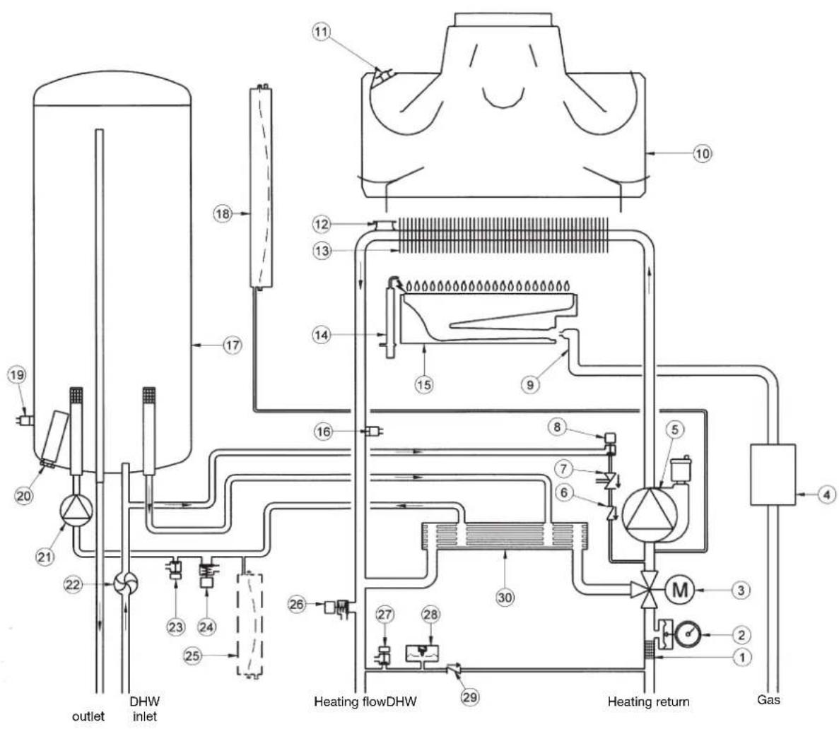
Figure 17
Key:
1 heating filter
2 pressure gauge
3 powered 3-way valve
4 gas valve with gas diaphragm
5 heating circuit pump with deaerator
6 check valve
7 disconnector
8 boiler filling tap
9 gas train with injectors
10 fumes conveyor
11 fumes thermostat
12 safety thermostat
13 water-fumes exchanger
14 Ignition/flame detection electrode
15 burner
16 NTC domestic hot water sensor
17 storage boiler
18 heating circuit expansion vessel
19 NTC heating probe
20 sacrificial anode
21 DHW circuit pump
22 DHW priority sensor
23 storage boiler drain tap
24 DHW circuit safety valve
25 DHW circuit expansion vessel (accessory)
26 boiler safety valve
27 boiler drain tap
28 hydraulic pressure switch
29 check valve on automatic by-pass
30 plate exchanger
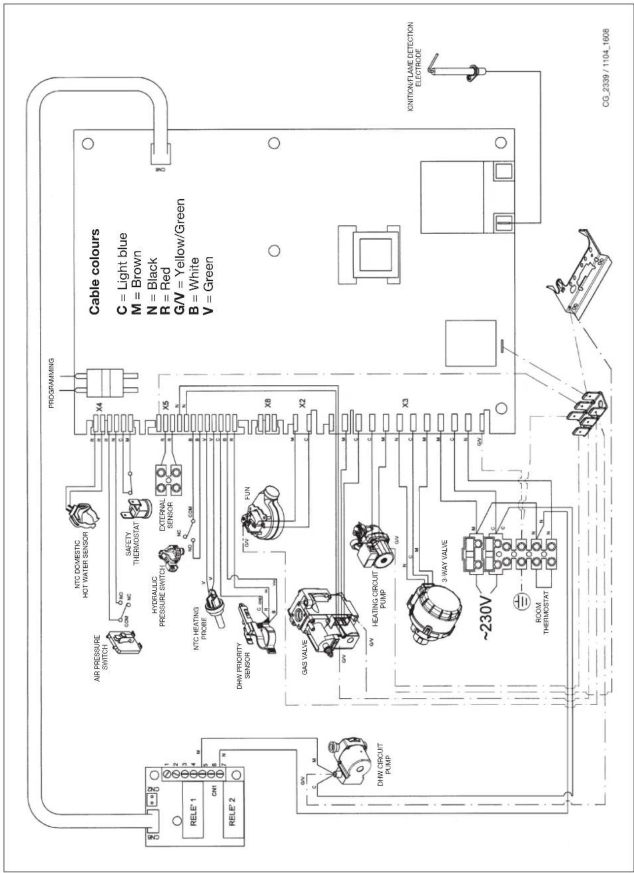
35. WIRING DIAGRAM
24 BIC FF
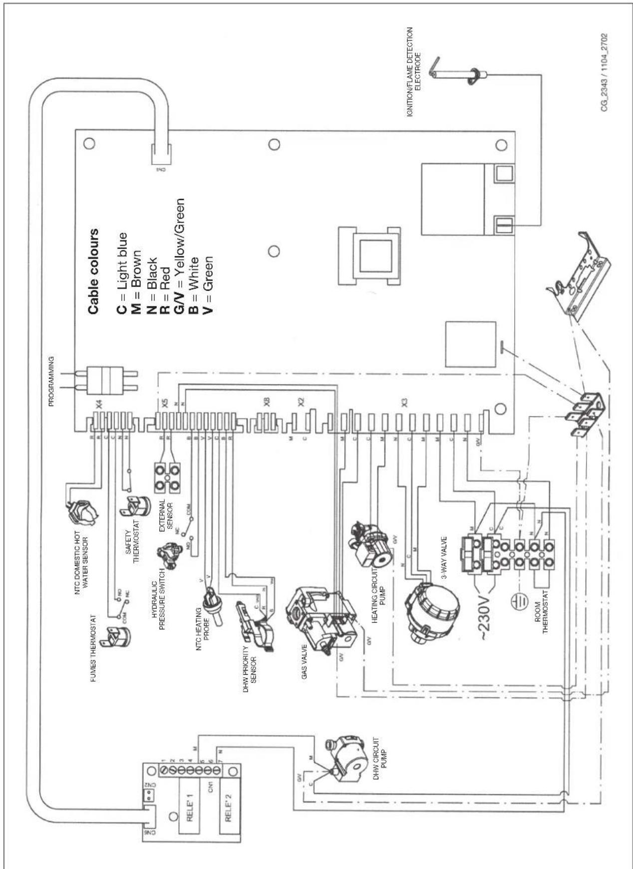
24 BIC
36. TECHNICAL SPECIFICATIONS
Protection against humidity and water (**)
IP X5D IP X5D
(*) according to EN 625 - (**) according to EN 60529
As DE DIETRICH constantly strives to improve its products, it reserves the right to modify the information contained in this document at any time and without prior notice. This document is issued purely for the sake of information and should not be considered as a contract with third parties.
Estimado Cliente,
L max = 4 m ( 60/100 mm)
10 m ( 80/125 mm)

L max = 4 m ( 60/100 mm)
10 m ( 80/125 mm)
L max = 3 m (∅ 60/100 mm)
9 m (∅ 80/125 mm)

L max = 3 m (∅ 60/100 mm)
9 m (∅ 80/125 mm)
0512 2001
L max = 10 m (∅ 80/125 mm)

L max = 8 m (∅ 80/125 mm)
L max = 9 m (∅ 80/125 mm)
(L1 + L2) max = 30 m
1010 0102/CG1643
Figura 13
9912070100
Figura 14

CG_2355_A / 1104_1605
L max = 4 m (∅ 60/100 mm)
10 m (∅ 80/125 mm)

L max = 4 m ( 60/100 mm)
10 m ( 80/125 mm)

L max = 3 m ( 60/100 mm)
9 m ( 80/125 mm)

L max = 3 m ( 60/100 mm)
9 m ( 80/125 mm)
0512_20001
L max = 10 m (∅ 80/125 mm)

L max = 8 m (∅ 80/125 mm)

L max = 9 m ( 80/125 mm)
(L1 + L2) max = 30 m
1010_0102/CG1643
Фигура 13

9912070100
LEGENDA SYMBOLI
Rysunek 13

9912070100
24. KONTROLA PARAMETRÓW SPALANIA

(L1 + L2) max = 30 m
1010_0102/CG1643
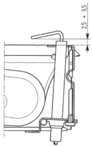
Figura 13
24. VERIFICAREA PARAMETRILOR DE COMBUSTIE
GOLIREA BOILERULUI
L max = 4 m ( 60/100 mm)
10 m ( 80/125 mm)
L max = 4 m ( 60/100 mm)
10 m ( 80/125 mm)

L max = 3 m ( 60/100 mm)
9 m ( 80/125 mm)

L max = 3 m ( 60/100 mm)
9 m ( 80/125 mm)
0512_2001
L max = 10 m (∅ 80/125 mm)
L max = 8 m (∅ 80/125 mm)

L max = 9 m (Ø 80/125 mm)
Εικόνα 13
9912070100
L max = 4 m (∅ 60/100 mm)
10 m (∅ 80/125 mm)
L max = 4 m (∅ 60/100 mm)
10 m (∅ 80/125 mm)
L max = 3 m (∅ 60/100 mm)
9 m (∅ 80/125 mm)
L max = 3 m (∅ 60/100 mm)
9 m (∅ 80/125 mm)
0512_2001
L max = 10 m (Ø 80/125 mm)

L max = 8 m (∅ 80/125 mm)
L max = 9 m ( 80/125 mm)
(L1 + L2) max = 30 m
1010 0102/CG1643
Рис.13
9912070100
График 2
ОПУСТОШЕНИЕ БОЙЛЕРА
1010 0102/CG1643
9912070100
图13
24. 燃烧参数的检测
图14
CG_2355_A/1104_1605
热水器清空
依照以下说明清空热水器:
- 关闭进水阀门;