
RET2000 M - Thermostat DANFOSS - Free user manual and instructions
Find the device manual for free RET2000 M DANFOSS in PDF.
| Product Type | Room Thermostat |
| Brand | Danfoss |
| Model | RET2000 M |
| Power Supply | 230 VAC ±15%, 50/60 Hz or 2.5-3 VDC (2 AA batteries) |
| Temperature Setting Range | Heating: 5-30 °C; Cooling: 16-36 °C |
| Operating Temperature Range | 0-45 °C |
| Contact Rating | 3 A (1) at 230 VAC |
| Switch Type | 1 x SPDT, Type 1B |
| Battery Life | 2 years minimum |
| Protection Rating | IP20 |
| Control | On/Off and Time Proportional Integral (TPI) |
| Operating Modes | Selectable heating/cooling |
| Dimensions (H x W x D) | 84 x 84 x 35 mm |
| Compliance | EN 60730-2-9 |
| Pollution Degree | Degree 2 |
| Rated Impulse Voltage | 2.5 kV |
| Ball Pressure Test | 75 °C |
| Software Class | A |
| ERP Class | IV (additional efficiency gain of 2%) |
| Recommended Mounting | At 1.5 m from the floor, away from drafts and heat sources |
| Advanced Settings | Lower limit (S1), upper limit (S2), setpoint temperature at power-up (S3) |
| Maintenance and Cleaning | Clean with a soft, dry cloth; do not use solvents |
| Safety | Installation by a qualified electrician or heating engineer; comply with IEEE standards |
Frequently Asked Questions - RET2000 M DANFOSS
User questions about RET2000 M DANFOSS
0 question about this device. Answer the ones you know or ask your own.
Ask a new question about this device
Download the instructions for your Thermostat in PDF format for free! Find your manual RET2000 M - DANFOSS and take your electronic device back in hand. On this page are published all the documents necessary for the use of your device. RET2000 M by DANFOSS.
USER MANUAL RET2000 M DANFOSS
ENGINEERING TOMORROW

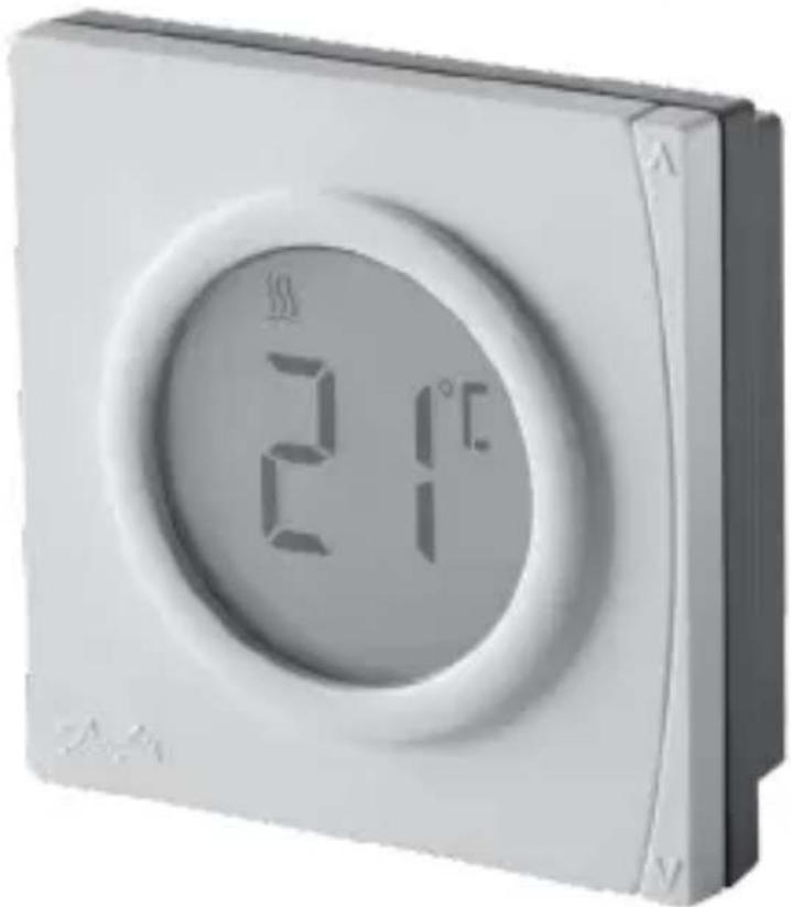
RET2000 B/M/MS
Electronic digital thermostat with LCD
Installation Guide
Danfoss Heating
For a large print version of these instructions please call Marketing on 0845 121 7400.
Danfoss can accept no responsibility for possible errors in catalogues, brochures, and other printed material. All trademarks in this material are property of the respective companies. Danfoss and the Danfoss logotype are trademarks of Danfoss A/S. All rights reserved.
Installation Instructions
| Specifications RET2000MS | RET2000M | RET2000B | |
| Operating Voltage 230Vac ±1 | 5%, 50/60Hz | 2.5 - 3 VDC (2xAA batteries) | |
| Output 230Vac Volt free | |||
| Setting temp. range 5-30°C (cooling 16-36°C) | |||
| Operating temp. range 0-45°C | |||
| Switch rating 3A (1) at 230Vac | |||
| Switch type 1 x SPDT Type 1B | |||
| Battery lifetime N/A Min. 2 years | |||
| IP rating IP20 | |||
| On/off control Yes | |||
| Chrono-proportional control Yes | |||
| Operating modes | Heating/Cooling selectable | ||
| Construction | EN 60730-2-9 | ||
| Control pollution situation | Degree 2 | ||
| Rated impulse voltage | 2.5kV | ||
| Ball pressure test | 75°C | ||
| Dimensions (mm) H84 x W84 | x D35 | ||
| Software Classification | A | ||
Danfoss Heating
3
Installation Instructions
| ERP Class | ||
| The products represented within this document are classified according to, and allow completion of, the Energy Related Product (ErP) Directive System Package fiche and the ErP system data label. ErP Labelling obligation is applicable from 26th September 2015. | ||
| ERP Class | Product Function and ErP Descri-p-tion | Additional efficiency gain |
| IV TPI Room Thermostat, for use with on/off output heaters An electronic room thermostat that controls both thermostat cycle rate and in-cycle on/off ratio of the heater proportional to room temperature. TPI control strategy reduces mean water temperature, improves room temperature control accuracy and enhances system efficiency. | 2% | Erp Class 4 |
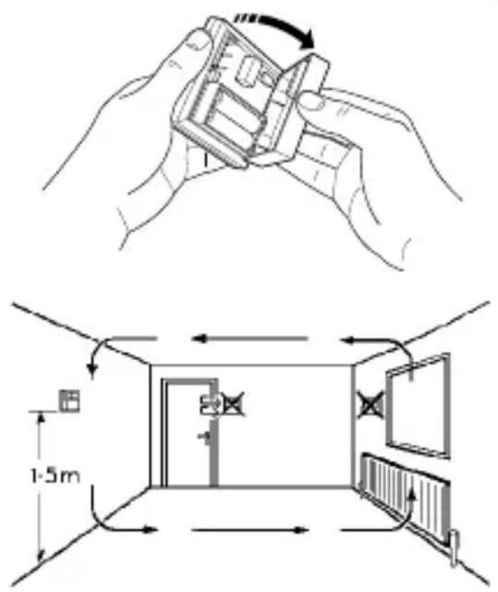
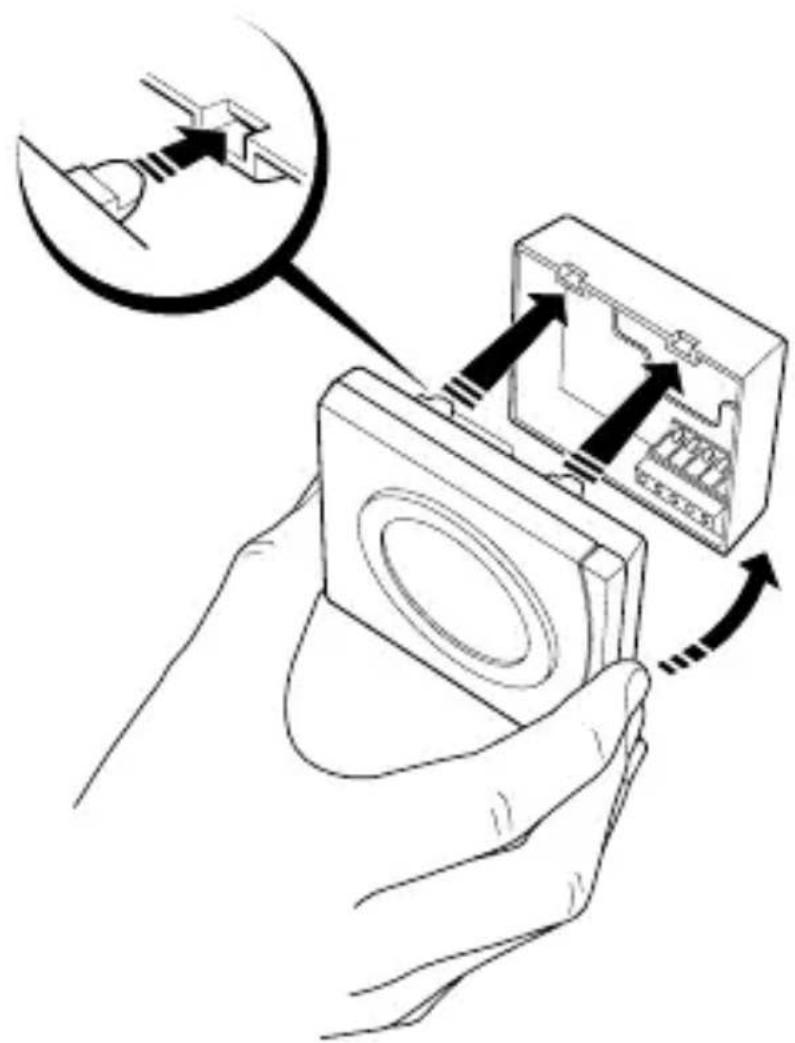
Mounting
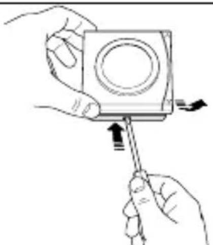
Fix at a height of 1.5m approx from the floor, away from draughts or heat sources such as radiators, open fires or direct sunlight.
Please Note: This product should only be installed by a qualified electrician or competent heating installer and should be in accordance with the current edition of the IEEE wiring regulations.
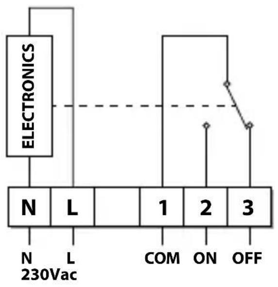
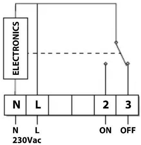
Wiring
GB
RET2000B
DE
DK
ES
FR
NL
RU
TR
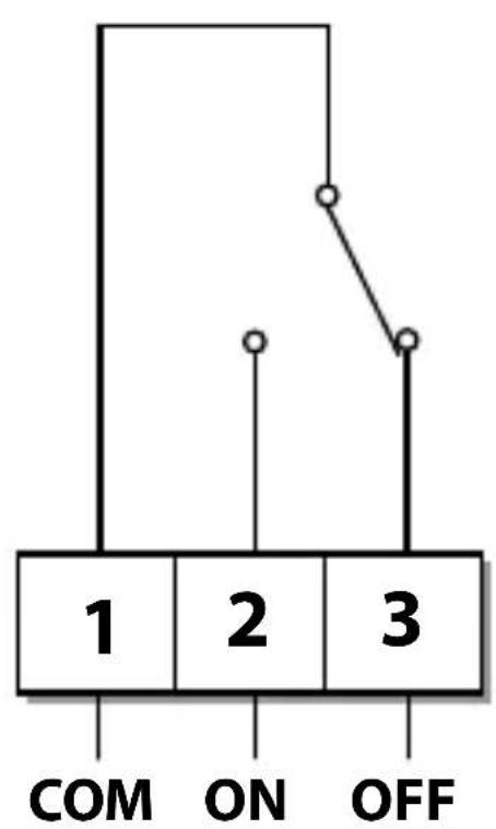

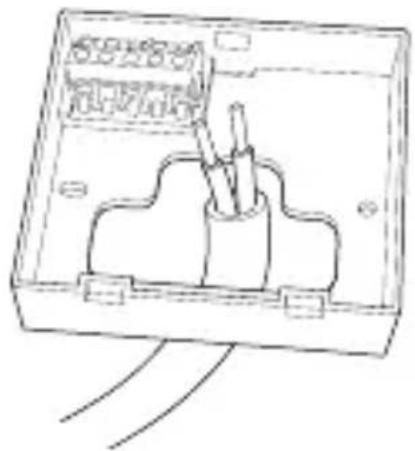
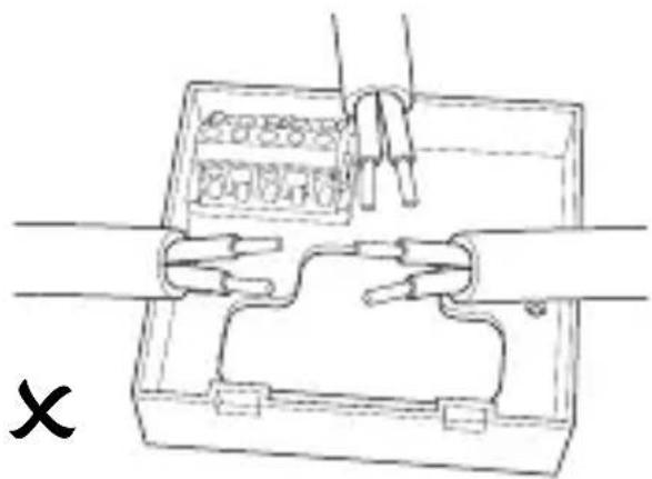
Wiring
RET2000M
RET2000MS
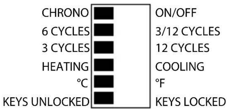
DIL switch settings
Slide the DIL switches to the settings required.

ON/OFF - output switches ON when below set temperature and OFF when above. (Reverse when in cool mode)
CHRONO - energy saving feature which fires the boiler at regular intervals to maintain a set temperature, achieving a constant ambient environment for the user.
use 6 or 12 Cycles for radiator systems
- use 3 Cycles for underfloor heating
DIL Switch Settings
Heating selection
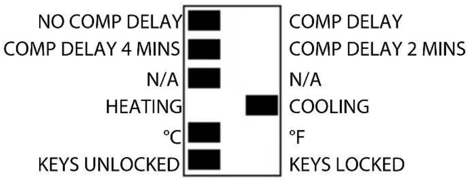
Cooling selection
Mounting
GB
DE
DK
ES
FR
NL
RU
TR
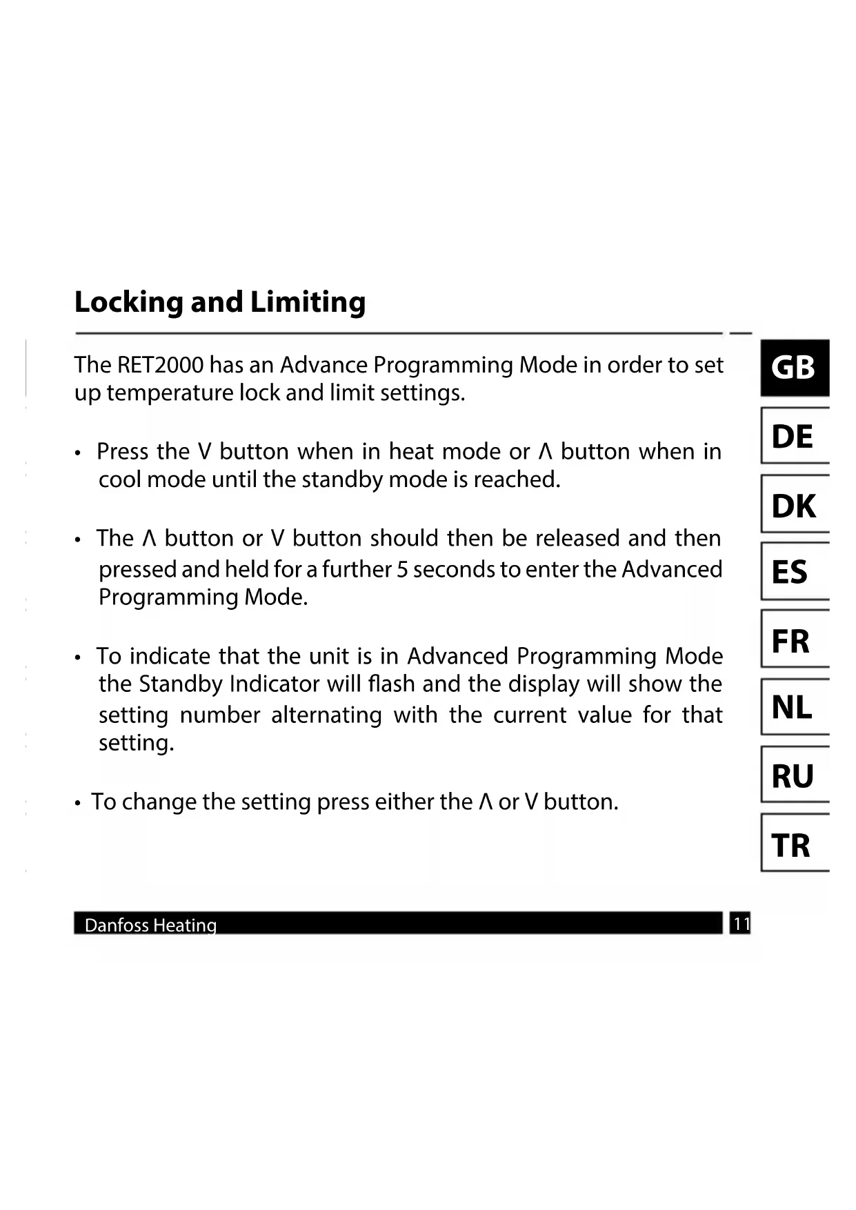
Locking and Limiting
The RET2000 has an Advance Programming Mode in order to set up temperature lock and limit settings.
- Press the V button when in heat mode or button when in cool mode until the standby mode is reached.
- The button or V button should then be released and then pressed and held for a further 5 seconds to enter the Advanced Programming Mode.
-
To indicate that the unit is in Advanced Programming Mode, the Standby Indicator will flash and the display will show the setting number alternating with the current value for that setting.
To change the setting press either the or V button. -
A simultaneous push and release of both buttons will scroll through the steps S1 to S3 and will save the current set value if altered.
- To exit Advanced Programming Mode and return to Standby Mode press and hold both buttons for more than 5 seconds.
- While in Advanced Programming Mode if no buttons are pressed for more than 2 minutes the unit will automatically return to Standby mode, and the value on the current setting will not be saved.
| S1 – Lower Temperature Limit |
| This setting allows for a Lower Temperature Limit to be set. The Lower Limit can be set between 5°C (41°F) and 30°C (86°F) in Heat mode, or between 16°C (61°F) and 36°C (97°F) in Cool mode. |
| Default – 5°C/41°F for Heat mode or 16°C/61°F for Cool mode. |
| S2 – Upper Temperature Limit |
| This setting allows for a Upper Temperature Limit to be set. The Upper Limit can be set between 5°C (41°F) and 30°C (86°F) in Heat mode, or between 16°C (61°F) and 36°C (97°F) in Cool mode. However, this will be limited by the Lower Temperature Limit set in S1 therefore the Upper Temperature Limit cannot be less than the Lower Temperature Limit. |
| Default – 30°C/86°F for Heat mode or 36°C/97°F for Cool mode. |
| S3 – Set Point Power-Up Temperature |
| This setting defines the set point at power up when Button Lock is enabled on the DIL switch. This can be set between the Lower and Upper Temperature Limits set in S1 and S2. |
| Default – 21°C/70°F for Heat mode or 24°C/75°F for Cool mode. |
Email: ukheating@danfoss.com
Website: www.heating.danfoss.co.uk
Part No 44035v03 07/15
VIRKP202

Brand : DANFOSS
Model : RET2000 M
Category : Thermostat