USER MANUAL TP5001 DANFOSS
TP5001 Range
Electronic Programmable Room Thermostat
Please Note:
This product should only be installed by a qualified electrician or competent heating installer and should be in accordance with the current edition of the IEEE wiring regulations.
Product Specification
| Thermostat features TP5001 | 1 (A) TP5001-RF TP5001M (A) | |
| Power supply 2 x AA/MN1 | 500/LRalkaline cells | 230V, ±15%, 50Hz |
| Memory back-up Retained | for life of product |
| Temperature Range Sensing | 5-30°C |
| Factory set calendar clock | Automatic summer/winter time change |
| Switching action of output relay | 3(1)A, 10-230V | N/A 3(1)A, | 10-230V, Type 1B |
| Transmission frequency (RF models) | N/A 433.92 | MHz N/A | |
| Transmission range (RF models) | N/A 30m max. N/A | |
| Remote sensor inputs (A models only) | Can be set by installer for remote temperature sensor, limit sensor, window contact or telephone activated switch contacts |
| Dimensions (mm) | 110 wide, 88 high, 28 deep |
| Design standard | EN60730-2-9 (EN300220 for RF) |
| Rated impulse voltage | 2.5kV |
| Ball hardness test | 75°C |
| Control pollution situation | Degree 2 |
| Temperature accuracy | ±1°C |
| Time accuracy | ±1 min. per month |
Important note RF products: Ensure that there are no large metal objects, such as boiler cases or other large appliances, in line of sight between the transmitter and receiver as these will prevent communication between thermostat and receiver.
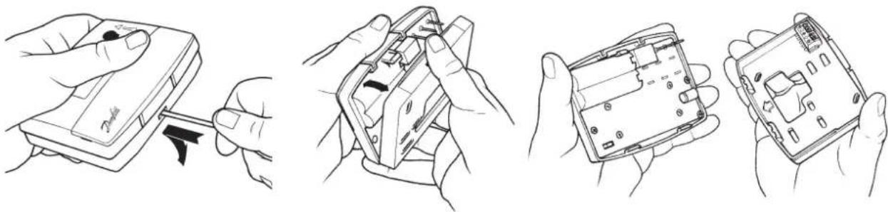
- First, remove the wallplate from the back of the unit.
natural_image
Line drawings showing four different hand-drawn views of a device's internal components, including a close-up and open case (no text or symbols)
- From the top left hand corner of the wallplate, there must be clearances of at least 15mm to the right, 15mm to the left, 30mm above and 100mm below in order to mount the plug-in module.
• Thermostat and Remote Room Sensor:
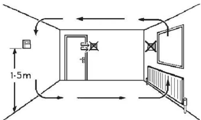
Fix at a height of approximately 1.5m from the floor, away from draughts or heat sources such as radiators, open fires or direct sunlight.
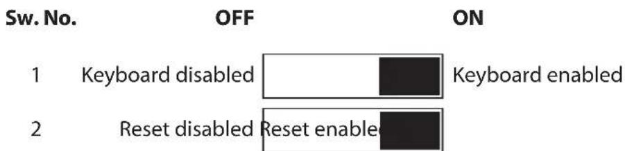
- Prior to mounting the unit the 2 DIL switches on the rear of the unit have to be moved to the required position. The factory presets are shown below.

natural_image
Diagram of a device rear panel showing internal wiring and a terminal block (no text or symbols)
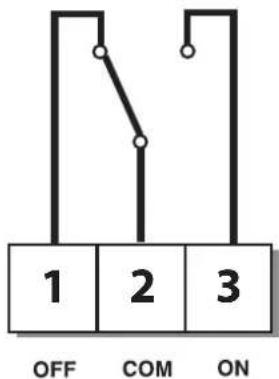
Wiring - TP5001
natural_image
Pure electrical circuit lines without any symbols
M 230V Models
Remote Sensor (A version only)
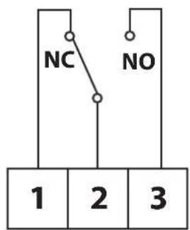
Output Connections, all hard wired models
Battery Installation
When installing the batteries in the TP5001 and TP5001 RF please ensure that the correct polarity is observed as per the markings on the inside of the battery compartment.
Important: After installing the batteries press and release the RESET button to start the unit. The display may appear blank until this is done. Once the button is released the display will appear. All date, time, programming and override settings are maintained for the life of the product.
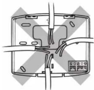
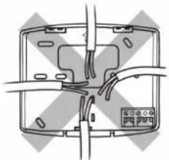
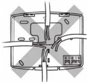
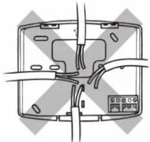
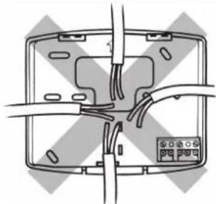
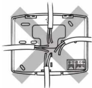
Some existing thermostats will have a Neutral and/or Earth wire connected. These are not required by the TP5001 (battery models) and must NOT be connected to any TP5001 terminals. Instead they should be made electrically safe and coiled in the
● recess at the back of the TP5001.
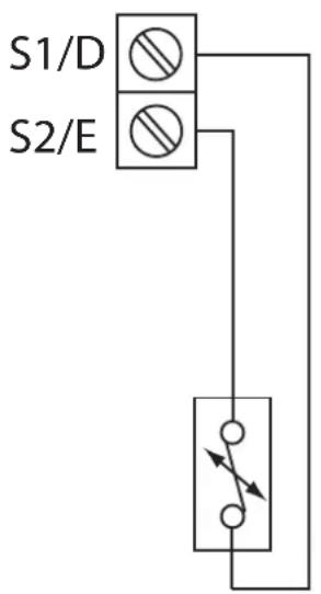
TP5001A and TP5001MA incorporate an input which can be used to connect one of the following:
1) remote room temperature sensor (sold as accessory).
2) limit sensor, for example, floor temperature sensor (sold as accessory).
3) window contacts, card reader contacts or teleswitch contacts.
See Installer Advanced Programming Options for set-up instructions.
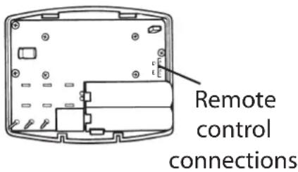
Terminal block for remote control/sensing is located on the circuit board above the battery compartment.
Confi gured for remote room sensor or limit sensor
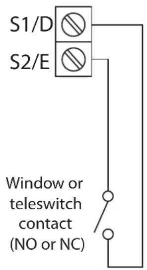
Configured for window contact or other contact such as teleswitch
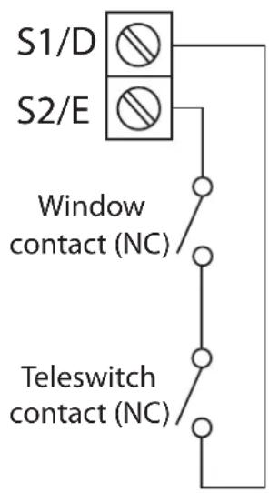
Confi gured for window contact and other contact such as teleswitch
RX Receiver Wiring (RF models only)
RX1
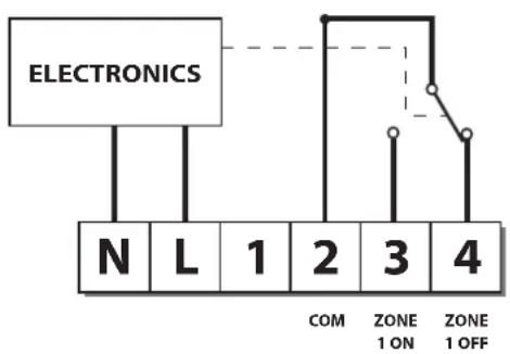
flowchart
graph TD
    A["ELECTRONICS"] --> B["N"]
    A --> C["L"]
    A --> D["1"]
    A --> E["2"]
    A --> F["3"]
    A --> G["4"]
    H["COM"] --> I["ZONE 1 ON"]
    J["ZONE 1 OFF"] --> K["Line with open circle"]
RX2 & RX3
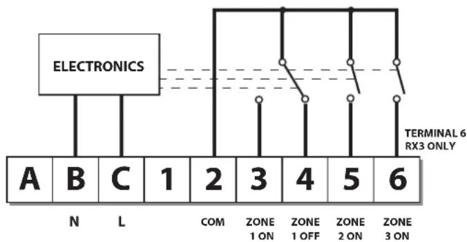
flowchart
graph TD
    A["Electronics"] --> B["Terminal 6 RX3 ONLY"]
    B --> C["1 ON"]
    B --> D["2 ON"]
    B --> E["3 ON"]
    B --> F["4 OFF"]
    B --> G["5 ON"]
    B --> H["6 ON"]
    style A fill:#f9f,stroke:#333
    style B fill:#ccf,stroke:#333
    style C fill:#cfc,stroke:#333
    style D fill:#fcc,stroke:#333
    style E fill:#cff,stroke:#333
    style F fill:#ffc,stroke:#333
    style G fill:#cfc,stroke:#333
    style H fill:#fcc,stroke:#333
1) For mains voltage operated systems link terminal 2 to mains live supply.
2) Power supply to unit must not be switched by timeswitch.
IMPORTANT
To ensure that the factory programmes are set and the micro-computer is operating correctly it is essential that you press and hold the RESET button before you begin any commissioning or programming.
Commissioning (RF models only)
If the thermostat and the receiver have been supplied together in a combined pack, the units have been paired in the factory and no commissioning is required (RX1 only).
To tune the RX receiver to the frequency of the thermostat signal, follow steps 1-5 below.
Step 1 TP5001-RF
Reset the unit by pressing the recessed reset button.
Step 2 Press and hold V and + buttons for 3 seconds (TP5001-RF now transmits unique signal continuously for 3 minutes).
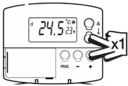
Step 3 RX1
Press and hold buttons PROG and CH1 for 3 seconds until green light fl ashes once.
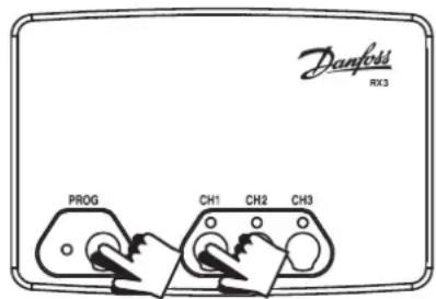
Step 4 RX2 (if applicable)
Stat 1 - perform steps 1-3 and 5.
Stat 2 - perform steps 1-2 and then press PROG and CH2 on RX2.
RX3 (if applicable)
Stat 1 - perform steps 1-3 and 5.
Stat 2 - perform steps 1-2 and then press PROG and CH2 on RX3 then step 5.
Stat 3 - perform steps 1-2 and then press PROG and CH3 on RX3.
Step 5 TP5001-RF
Press V or to select temperature - the unit will revert back to operating mode.
Installer advanced programming options
TP5001 incorporates a number of advanced features which can be set by the user. These are accessed via a User Advanced Programming Mode, please refer to User Advanced Programming in the user instructions for details.
Installer advanced programming options
TP5001 incorporates an additional number of advanced features which can be set by the installer to improve the operating efficiency of the system and where required, to change the user functionality of the product. These are accessed via an Installer Advanced Programming Mode. These settings are optional and need only be made if there is a demand for the enhanced functions.
Entering Installer Advanced Programming mode
To access the Installer Advanced Programming Mode follow the steps below:
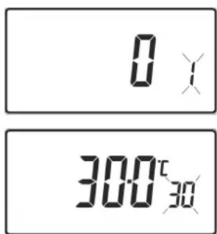
a) Press and hold V and PROG for 3 seconds to enter User Advanced Programming, the display will change to figure opposite.
b) Press and hold V, and PROG for 5 seconds to enter Installer Advanced Programming, the display will change to fi gure opposite.
c) Use + and - keys to scroll backwards and forwards between options then V and keys to change the option settings. The flashing digit on the right hand of the display indicates the number of the selected option. The large characters display the option value selected.
d) To return to RUN, press and hold PROG until colon in the display blinks.
| Option 30 - Set upper limit of temperature range |
| This allows the upper limit of the thermostat setting range to be electronically limited. Press + until Option 30 is displayed, use V and Λ to select required setting. | 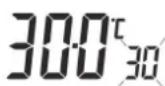 |
| Setting 40 - 5°C (Factory setting is 30°C) |
| Option 31 - Set lower limit of temperature range |
| This allows the lower limit of the thermostat setting range to be electronically limited. Press + until Option 31 is displayed, use V and Λ to select required setting. | 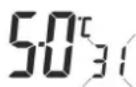 |
| Setting 5 - 40°C (Factory setting is 5°C) |
| Option 32 - Enable Off at lower limit |
| This enables an OFF function to be selected if a set point below the lower limit is selected. Press + until Option 32 is displayed, use V and Λ to select required setting. | 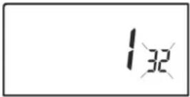 |
| Setting 0 Disabled |
| Setting 1 Enabled (factory setting) |
| Option 33 - Enable On at upper limit |
| This enables an ON function to be selected if a set point above the upper limit is selected. Press + until Option 33 is displayed, use V and Λ to select required setting. | 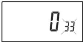 |
| Setting 0 Disabled (factory setting) |
| Setting 1 Enabled |
| Option 34 - Select on/off or chrono-proportional |
| This allows the thermostat to be set to run in On/Off mode or for a chrono-proportional cycle rate to be selected. Press + until Option 34 is displayed, use V and Λ to select required setting. |
| 0 On/Off |
| 3 3 cycles per hour |
| 6 6 cycles per hour (factory setting) |
| 9 9 cycles per hour |
| 12 12 cycles per hour |
| Option 35 - Set integration time (Option 34 set to 3, 6, 9 or 12)(seek advice prior to adjusting) |
| This adjusts the integration time of the PI algorithm to increase control accuracy. It should only be adjusted after seeking advice from the manufacturer. Press + until Option 35 is displayed, use V and Λ to select required setting. |
| 2.5 Integration time set to 2.5% (factory setting) |
| 5 Integration time set to 5% |
| 10 Integration time set to 10% |
| Option 36 - Set temperature override rule |
| This establishes the degree of temperature override available to the user. Press + until Option 36 is displayed, use V and Λ to select required setting. |
| Setting 0 | No limit (factory setting) |
| Setting 1 | Limited to ±2°C |
| Setting 2 | No override allowed |
| Option 37 - Set time duration of override rule (Option 36 set to 1 or 2) |
| This establishes the duration of a temperature override available to the user. Press + until Option 37 is displayed, use V and Λ to select required setting. |
| Setting 0 | Next event (factory setting) |
| Setting 1 | hour |
| Setting 2 | hours |
| Setting 3 | hours |
| Setting 4 | 4 hours |
| Option 38 - Relay state on low battery detect(battery products only) |
| This establishes the position that the relay is driven to when the unit shuts down due to low battery state. Press + until Option 38 is displayed, use V and Λ to select required setting. |
| Setting 0 | Relay parked with output OFF (factory setting) |
| Setting 1 | Relay parked with output ON |
| Option 40 - Number of Events per Day |
| This sets the thermostat to operate with either 2, 4 or 6 switching events per day or to run it in stat mode. Press + until option 40 is displayed, use Λ or V to select required setting. |
| 1 Stat | mode |
| 2 Two | switching events per day |
| 4 Four | switching events per day |
| 6 Six s | switching events per day (Factory setting) |
| Option 41 - Operating Mode (5/2 day or 24 hour) |
| This sets the thermostat to operate using either 5/2 day or 24 hour mode. Press + until option 41 is displayed, use Λ or V to select required setting. | 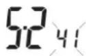 |
| 5-2 5/2 | day (Factory setting) |
| 24 24 hour |
| Option 70 - Keyboard disable rules |
| This establishes the degree of functionality of the keyboard available to the user. It is only active if DIL switch 1 is set to “Disabled”. Press + until Option 70 is displayed, use V and Λ to select required setting. |
| Setting 0 | Normal lock: Programming functions locked (factory setting) |
| Setting 1 | Full lock: All keys are disabled |
| Option 71 - Random start rules (24V/230 Volt models only) |
| This enables a random start on power-up following a power cut to reduce load on the electrical network. Random delay is in the range of 2 - 90 seconds. Press + until Option 71 is displayed, use V and Λ to select required setting. | 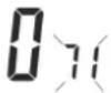 |
| Setting 0 Disabled (factory setting) |
| Setting 1 Enabled |
| Option 72 - Owner site reference number |
| This enables multi-site owners to store a site reference number in the thermostat. Press + until Option 72 is displayed, use V and Λ to select required setting. |
| Setting Any value between 00 and 99 can be set |
| Factory setting is 00 |
| Option 73 - Owner thermostat reference number |
| This enables site owners to store a thermostat reference number in the thermostat. Press + until Option 73 is displayed, use V and Λ to select required setting. |
| Setting Any value between 000 and 999 can be set Factory setting is 000 |
| Factory setting is 000 |
| Option 74 - Date format for calendar clock |
| This allows date format to be chosen. Press + until Option 74 is displayed, use V and Λ to select required setting. |  |
| Setting 0 European rules (dd/mm/yy), (Factory setting) |
| Setting 1 North American rules (mm/dd/yy) |
| Option 81 - Thermostat calibration bias |
| This allows the thermostat calibration to be biased by up to ±1.5°K. Press + until Option 81 is displayed, use V and Λ to select required setting. | 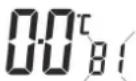 |
| Setting Any value between ±1.5 (Factory setting is 0°C) |
| Option 90 - Defi ne remote sensor type, “A” models only |
| This allows type of remote sensor input type to be defined. Press + until Option 90 is displayed, use V and Λ to select required setting. |  |
| Setting 0 No remote sensor fitted (Factory setting) |
| Setting 1 Remote room or duct sensor fitted, internal sensor disabled |
| Setting 2 Remote limit sensor fitted, refer to option 93 to define set-point |
| Setting 3 Confi gured as digital input for window, card reader or teleswitch, refer to option 94 to defi ne o/c or s/c. |
| Option 93 - Set limit sensor set-point, “A” models only,(option 90 set to 2) |
| This allows the thermostat limit sensor to be set,typical application is floor htg. Press + until Option93 is displayed, use V and Λ to select requiredsetting. If the temperature sensed by the limitsensor exceeds the limit setting the output will beturned off until the temperature has dropped by2°C “F10” will flash in the display. | 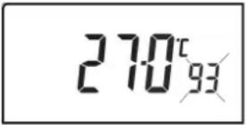 |
| Setting Any value between 20 - 50°C (Factory setting is 27°C) |
| Option 94 - Conf gure digital input switch type, “A” models only,(option 90 set to 3) |
This allows switch type of digital input to be configured. Press + until Option 94 is displayed, use V and Λ to select required setting. 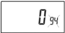 |
| Setting 0 | Contacts NC, open circuit contact to force unit into thermostat mode, short circuit contacts to return to normal operation |
| Setting 1 | Contacts NO, short circuit contacts to force unit into thermostat mode, open circuit contacts to return to normal operation (Factory setting) |
Bitte beachten Sie:
natural_image
Line drawings showing four steps of assembling a smartphone case, with no visible text or symbols.
natural_image
Diagram of a device rear panel with cable and indicator lights (no text or symbols)
Verkabelung - TP 5001
TP 5001 M(A) Version (230V)

Output Connections, all hard wired models
AUS EDOM
natural_image
Diagram of a device rear panel with mounting holes and internal components (no text or labels)
natural_image
Line drawings showing hand holding a smartphone with a cable being inserted, and three views of the device (no text or symbols present)
natural_image
Diagram of a device rear panel showing cable routing and connector (no text or symbols)
Cableado - TP5001
natural_image
Diagram of a device interior with wires and connectors, no text or symbols present
natural_image
Line drawings showing hands assembling a device into a plastic housing (no text or symbols)
natural_image
Diagram of a device rear panel showing internal wiring and ports (no text or labels)
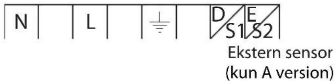
El-tilslutning - TP5001
natural_image
Pure electrical circuit lines without any symbols
Udgangsforbindelser,
alle kabelforbundne
modeller
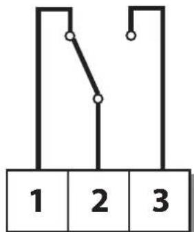
M 230V Modeller
flowchart
graph TD
    A["1"] --> B["2"]
    B --> C["3"]
Fra COM Til
natural_image
Diagram of a device rear panel with labeled ports and connectors (no text or symbols present)
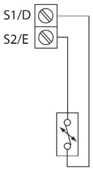
Ekstern sensor forbindelser
natural_image
Line drawings showing hands installing or adjusting a device component, with no visible text or symbols.
natural_image
Diagram of a device rear panel with cable and connector (no text or symbols)
natural_image
Pure electrical circuit lines without any symbols
Bedrading - TP5001
M-modellen 230V
natural_image
Diagram of a device rear panel with internal components and a cursor pointing to a component (no text or symbols)
natural_image
Line drawings showing hands installing or adjusting a device component, with no visible text or symbols.
natural_image
Diagram of a device rear panel with cable and indicator lights (no text or symbols)
natural_image
Diagram of a device with wires and connectors, no text or symbols present
Câblage - TP5001
Important note RF products: Ensure that there are no large metal objects, such as boiler cases or other large appliances, in line of sight between the transmitter and receiver as these will prevent communication between thermostat and receiver.
natural_image
Line drawings showing hands assembling a device with a USB cable, including a close-up of the internal components (no text or symbols present)
natural_image
Diagram of a device rear panel showing cable routing and ports (no text or labels)
natural_image
Pure electrical circuit lines without any symbols
Cablaggio - TP5001
www.danfoss.com/BusinessAreas/Heating
This product complies with the following EC Directives: Electro-Magnetic Compatibility Directive.
(EMC) (2004/108/EC)
Low Voltage Directive.
(LVD) (2006/95/EC)
CE