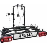
Saffier III 91535 - Bike rack Pro-User - Free user manual and instructions
Find the device manual for free Saffier III 91535 Pro-User in PDF.

| Product type | Bike carrier for trailer hitch |
| Brand | Pro-User |
| Model | Saffier III 91535 |
| Capacity | 3 bikes (max. 20 kg per bike) |
| Net weight | 17 kg |
| Maximum load on bike carrier | 60 kg |
| Hitch compatibility | Standard trailer hitch (non-aluminum) |
| Lighting type | Rear lights, turn signals, brake lights, fog light, reverse light (depending on plug) |
| Lighting power supply | 7-pin plug (Jaegers) or 13-pin plug (Jaegers) |
| Tilt function | Yes, for trunk access |
| Bike attachment | Extendable wheel holders + frame clamps + straps |
| Certification | European certification RWD |
| Materials | Steel |
| Maintenance | Water jet cleaning, lubrication of moving parts, bolt inspection |
| Warranty | 2 years |
| Spare parts | Original spare parts available |
| Repairability | Possible replacement of worn or damaged parts |
| General information | Assembly and safety instructions included |
Frequently Asked Questions - Saffier III 91535 Pro-User
User questions about Saffier III 91535 Pro-User
0 question about this device. Answer the ones you know or ask your own.
Ask a new question about this device
Download the instructions for your Bike rack in PDF format for free! Find your manual Saffier III 91535 - Pro-User and take your electronic device back in hand. On this page are published all the documents necessary for the use of your device. Saffier III 91535 by Pro-User.
USER MANUAL Saffier III 91535 Pro-User
UK: Assembly instruction and safety regulations
natural_image
Mechanical vehicle with attached sensors and a 'SAFFIER 3' license plate (no text or symbols on the device itself)| • Maximale kogeldruk• Max. Stützlast Anhängerkupplung• Max. ball pressure• Force de traction maximale de láttache remorque | • Gewicht fietsendrager• Eigengewicht Fahrradträger• Weight bike carrier• Le poids à vide du portevélos | • Max. belasting• Max. nutzlast am Fahrradträger• Max. load• Charge maximum |
| 50kg | 17kg | 33kg |
| 60kg | 17kg | 43kg |
| 75kg | 17kg | 58kg |
| 90kg | 17kg | Max. 60kg |

text_image
PROUSER BIKE CARRIERS® USERl n h o u d s o p g a v e
• I n t r o d u c t i
- Important information 31
- Mounting the bike carrier 32
- Mounting of the bike carrier onto the hitch ball 36
- Tilting mechanism 36
• The license plate holder & Lighting 37
- Mounting of the bikes on the bike carrier 38
• S a f e t y r e g u l a t
- Maintenance & guarantee 40
• Part list & exploded view 41
Table des matières
natural_image
Black-and-white photo of a black SUV with multiple bicycles parked in front, no visible text or symbols on the bicycles or background.

natural_image
Close-up of a mechanical device with two metallic components and a central shaft (no visible text or symbols)natural_image
Mechanical frame assembly with mounting brackets and a central component (no visible text or symbols)Stap 2
Onderdelen:

natural_image
Mechanical frame assembly with metal frames and mounting joints (no visible text or symbols)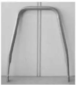
natural_image
Metallic curved bracket or support structure against a plain wall (no text or symbols)
natural_image
Close-up of mechanical components including bolts, nuts, and a hexagonal nut (no text or symbols visible)De montage:
natural_image
Close-up of a mechanical device with a black handle and cylindrical component (no visible text or symbols)Eindresultaat:
natural_image
Mechanical device with metal frame and handle, no visible text or symbolsStap 3
Onderdelen:
De montage:
natural_image
Close-up of a mechanical component with two metallic clips and a central hub, no visible text or symbolsnatural_image
Close-up of medical or laboratory equipment with curved transparent tubing and a central rod, no visible text or symbolsMarkering
Kunststof
natural_image
Mechanical vehicle chassis with articulated arms and mounting feet (no visible text or symbols)Stap 4
Onderdelen:

natural_image
Mechanical assembly with metal frame and multiple wheels (no visible text or symbols)
natural_image
Product display of mechanical components including rods, tools, and a circular device with four square buttons (no visible text or symbols)De montage:
natural_image
Close-up of a black-and-white cable with a strap and connector (no visible text or symbols)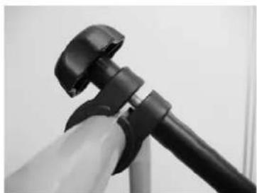
natural_image
Close-up of a black and white object resembling a camera or tripod, with no visible text or symbols.natural_image
Black-and-white photo of a mechanical vehicle with a 'SAFFIER 3' license plate, no visible text or symbols on the vehicle itself.MONTAGE VAN DE FIETSENDRAGER OP DE TREKHAAK
natural_image
Black-and-white photo of a small electronic device with a metallic body and a small cylindrical component, placed on a textured surface (no visible text or symbols)natural_image
Interior view of a laboratory apparatus with labeled components and directional arrows (no readable text or symbols)Vergrendelingshendels
natural_image
Black-and-white photo of a bicycle parked on a roadside with a car partially visible nearby (no text or symbols)natural_image
Close-up of a black plastic electrical plug with wires, no visible text or symbolsnatural_image
Close-up of a mechanical assembly with curved and straight components, no visible text or symbolsnatural_image
Close-up of a bicycle's wheel and suspension system, showing metal railings and a knotted car (no text or symbols visible)natural_image
Close-up of a motorcycle's front suspension system with visible hoses and brackets (no text or symbols)VEI LIGHEIDVOORSCHRIFTEN
natural_image
Close-up of a mechanical lever mechanism with a knob and control panel (no visible text or symbols)text_image
Exploded view diagram of a vehicle chassis with numbered parts for identificationEINFÜHRUNG
natural_image
Black SUV front view with bicycles parked in front (no visible text or symbols)

natural_image
Mechanical frame assembly with four metal components and mounting brackets (no visible text or symbols)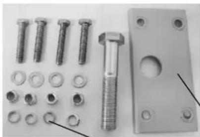
natural_image
Collection of metal fasteners and bolts including bolts, bolts, and a bolted plate (no text or symbols visible)
natural_image
Close-up of a black rectangular electronic component with a metallic spherical body and mounting flanges (no visible text or symbols)Die Montage:
natural_image
Close-up of a black rectangular electronic component mounted on a metal bracket, with two arrows pointing to its top section (no visible text or symbols)natural_image
Close-up of a laboratory apparatus with three metal fixtures and a central glass component (no visible text or symbols)natural_image
Mechanical assembly frame with metal components and mounting holes (no visible text or symbols)Step 2
Bauteile:
natural_image
Mechanical frame assembly with mounting flanges and central block (no visible text or symbols)
natural_image
Metallic support structure with curved metal frame and vertical line (no text or symbols)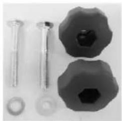
natural_image
Close-up of mechanical components including screws, bolts, and a hexagonal nut (no text or symbols visible)Die Montage:
natural_image
Close-up of a mechanical device with black lever and adjustment knob (no visible text or symbols)Endergebnis:
natural_image
Mechanical device with metal frame and lever mechanism (no visible text or symbols)Step 3
Bauteile:
Die Montage:
natural_image
Close-up of a mechanical component with two black components and a metallic fitting (no visible text or symbols)natural_image
Close-up of medical or laboratory equipment with transparent tubing and a central rod, no visible text or symbolsnatural_image
Mechanical assembly with metal frame and multiple levers (no visible text or symbols)Step 4
Bauteile:

natural_image
Mechanical device with articulated arms and wiring, no visible text or symbols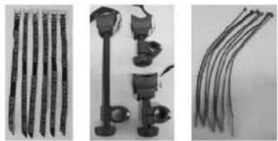
natural_image
Three-panel image showing different types of cable connectors and accessories, no visible text or symbols.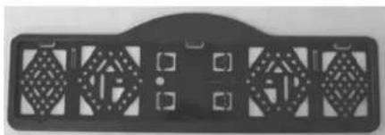
natural_image
Black rectangular object with diamond-shaped cutouts and small square buttons, resembling a vehicle or electronic component (no visible text or symbols)Die Montage:
natural_image
Close-up of a black plastic clamp attached to a coiled wire, no visible text or symbols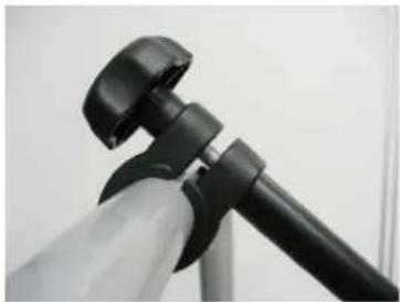
natural_image
Close-up of a black and white object resembling a tripod or camera mount (no visible text or symbols)natural_image
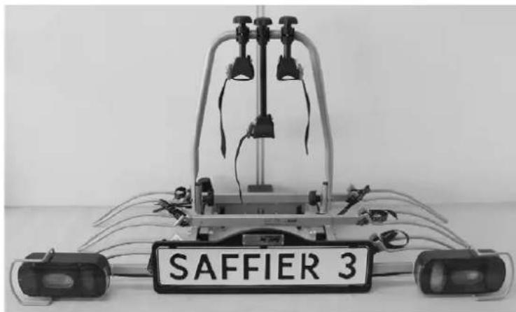
Mechanical device with labeled 'SAFFIER 3' and multiple sensors, no readable text or symbols beyond the labelnatural_image
Black-and-white photo of a small mechanical device with a black box and attached sensor, placed on a textured surface (no visible text or symbols)natural_image
Interior view of a laboratory apparatus with labeled components and directional arrows (no readable text or symbols)Verriegelungsgriffe
natural_image
Black-and-white photo of a parked bicycle on a roadside, with a car partially visible in the background (no text or symbols)natural_image
Close-up of a black electrical plug with attached wires (no visible text or symbols)natural_image
Close-up of a mechanical assembly with curved metal components and rods (no visible text or symbols)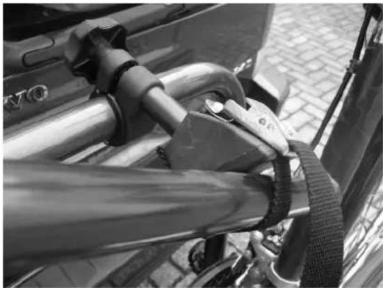
natural_image
Close-up of a bicycle tire buckle being adjusted, mounted on a metal frame (no visible text or symbols)natural_image
Close-up of a motorcycle front bumper with visible suspension and branding (no readable text or symbols)SI CHERHEI TSVORSCHRI FTEN
natural_image
Close-up of a mechanical lever mechanism with a spherical knob and control buttons (no visible text or symbols)text_image
Exploded view diagram of a mechanical device with numbered components for identificationINTRODUCTION
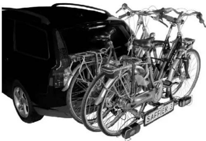
The Pro-User SAFFIER III bike carrier is part of the family of bike carriers manufactured by Tradekar Benelux BV.
√ Hitch ball bike carrier
√ Suitable for almost all types of hitch balls, bikes and wheel dimensions
√ Safe and reliable, easy to tilt bike carrier for the transport of 3 bicycles
√ The bikes are held in stable, adjustable wheel holders
√ Fixing of the bicycles on the frame, so no force on the pedals of your bike
√ Flexible bike holding arms
√ European permission given by the RDW
√ Lighting via a 7 and 13 pin (Jaegers) plug
√ Easy and quick fitting on the hitch ball
√ The trunk of your car is always accessible by the easy to use tilting system
√ Almost no influence on the driving behaviour of your car
√ Including fog light and reverse driving lighting (only working via the 13-pin plug)
natural_image
Black SUV front view with bicycles attached to rear trunks, no visible text or symbols on the vehicles or background

Read the following safety- and operating instructions carefully and act accordingly before using the bike carrier.
IMPORTANT INFORMATION
Read these instructions carefully before using the product for the first time.
Do not use this product until the manual and safety regulations are read and are entirely clear.
The assembly and installation of the bike carrier can only be done according to this instruction manual.
The steps that are mentioned and the safety regulations for assembly, handling and use of the bike carrier need to be followed! The slightest non conformity can lead to incorrect assembly or wrong use.
The carrier is suitable for the transport of three bikes at most. Please check the maximum permissible ball load. You can find it on the identification plate of the hitch ball of your car (for most cars this is 75kg). The total weight of the carrier with the bikes cannot exceed the maximum permissible ball load of the hitch ball.
The maximum permissible load for the carrier itself may be 60kg. The net weight of the carrier is 17kg.
| Max. permissible ball load | Weight bike carrier Max. load | |
| 50kg | 17kg | 33kg |
| 60kg | 17kg | 43kg |
| 75kg | 17kg | 58kg |
| 90kg | 17kg | Max. 60kg |
Not suitable for the use on an aluminium hitch ball.
Keep these instructions in your car.
CONSUMER HELPDESK & SUPPORT

+31 (0) 345-470998 (Monday till Thursday 8:30-12:30)

service@tradekar.nl
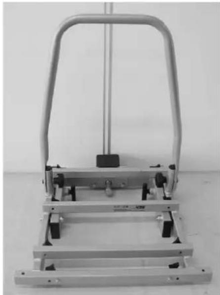
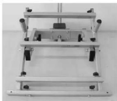
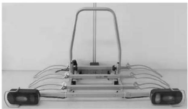
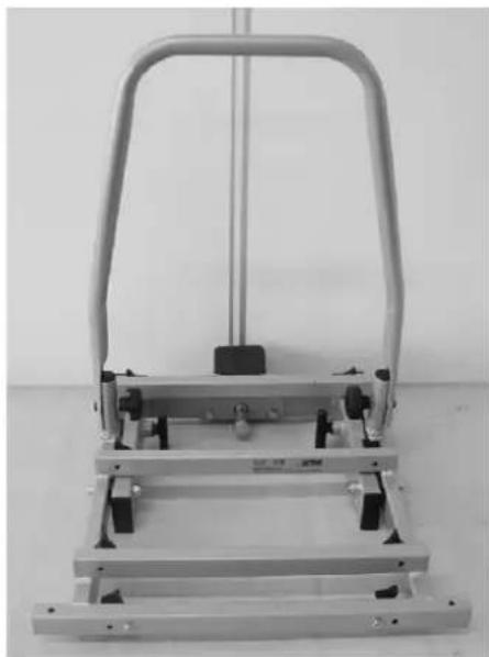
MOUNTING THE BIKE CARRIER
The bike carrier comes unassembled. Remove all parts from packaging and arrange them in a well-organized way. The instructions will clearly describe and show the parts that you need for each step and how to assemble the bike carrier.
Step 1
Parts:
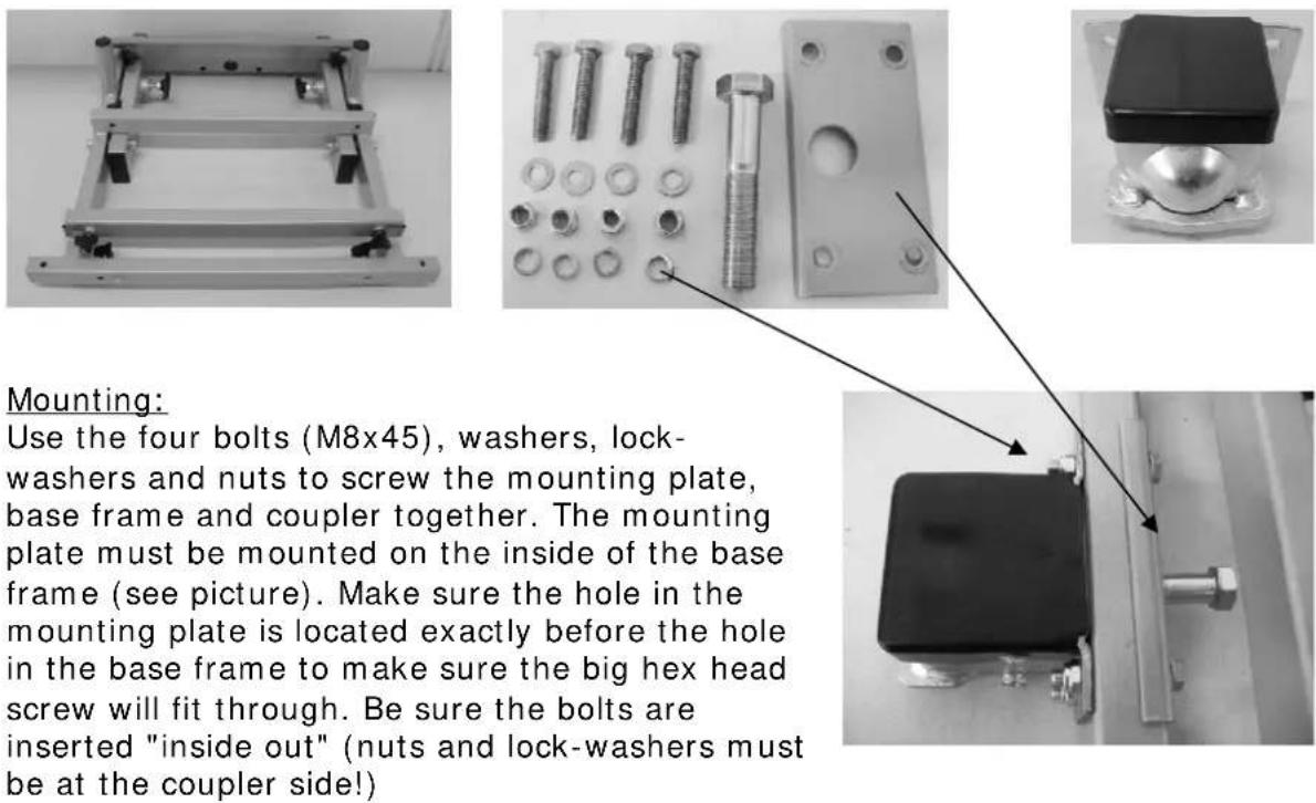
Mounting:
Use the four bolts (M8x45), washers, lock-washers and nuts to screw the mounting plate, base frame and coupler together. The mounting plate must be mounted on the inside of the base frame (see picture). Make sure the hole in the mounting plate is located exactly before the hole in the base frame to make sure the big hex head screw will fit through. Be sure the bolts are inserted "inside out" (nuts and lock-washers must be at the coupler side!)
natural_image
Close-up of a mechanical device with three metal components and a central metallic fixture (no visible text or symbols)If you tilt the inner frame (you need to pull out and rotate the two locking pins, see explanation on page 36), it will be easier to put the mounting plate in its place and tighten the nuts! Turn the two locking pins back into the secure position to be sure the inner frame will not tilt while you are mounting.
Now screw the big hex head screw (M16x90) approximately 1cm into the coupling. (see picture).
End result:
natural_image
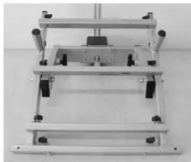
Mechanical frame assembly with mounting holes and a central component (no visible text or symbols)Step 2
Parts:
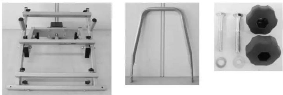
Mounting:
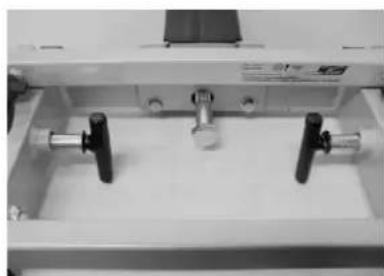
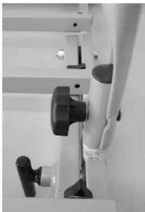
Slide the U-frame against the outside of the U-frame holders of the base frame. Secure this U-frame with the supplied carriage bolts (M8x60), washers and plastic rotary knobs.
Make sure the plastic rotary knobs are on the inside (see picture).
Please note you have to firmly tighten both rotary knobs so that the U-frame will come on its place well.
Tilt the inner frame back into the upright position as soon as this mounting is ready. This simplifies the continuation of the mounting.
natural_image
Close-up of a mechanical device with black lever and adjustment knob (no visible text or symbols)End result:
natural_image
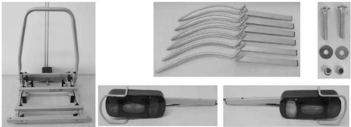
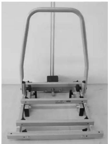
Mechanical lever mechanism with metal frame and handle (no visible text or symbols)Step 3
Parts:
natural_image
Mechanical device with metal frame and support structure (no visible text or symbols)
natural_image
Close-up of multiple metallic curved metal blades arranged diagonally (no text or symbols visible)
natural_image
Close-up of a black car key with a metallic handle and silver strap (no visible text or symbols)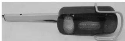
natural_image
Close-up of a handheld electronic device with a cylindrical body and handle (no visible text or symbols)Mounting:
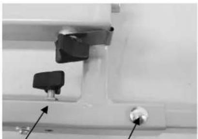
Slide the two rear light holders (incl. lights) into the light holder rail (the square
tube at the front of the base frame). Make sure the light marked with an "R" is mounted on the right side (the fog light should be placed on the left side). Screw both holders on with the two hex head screws (M6), washers on both sides and the self-locking nut (M6) and attach the screw downwards. To make sure the lights are securely fastened, you should tighten the plastic star knobs, which are located at the back of the light holder rail.
natural_image
Close-up of mechanical components with arrows pointing to features (no visible text or symbols)Plastic star knob
carriage bolt
text_image
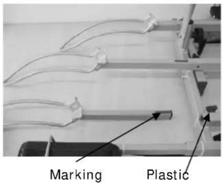
Marking PlasticSlide the six wheel holders into the openings in the base frame. Make sure to slide the wheel holders into the frame with the ends pointing downwards (see picture). Fasten the wheel holders using the plastic star knobs. When adjusting the wheel holders, they may not be pulled out beyond the red marking!
star
knob
End result:
natural_image
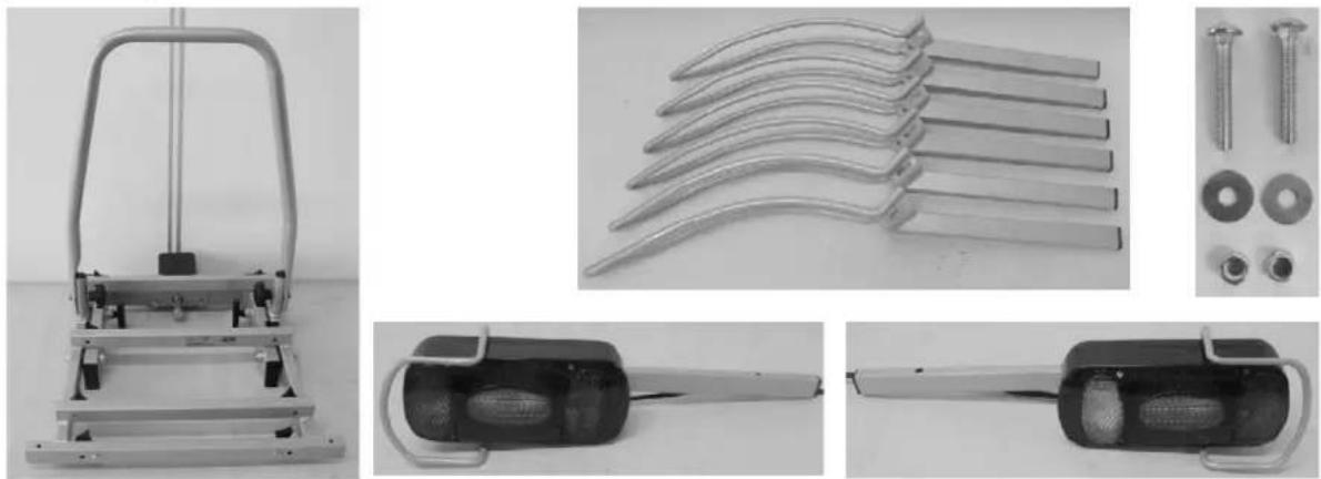
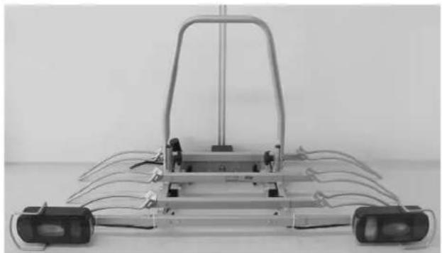
Front view of a metallic robotic vehicle chassis with multiple wheels and a frame (no visible text or symbols)Step 4
Parts:

natural_image
Mechanical device with articulated arms and wiring, no visible text or symbols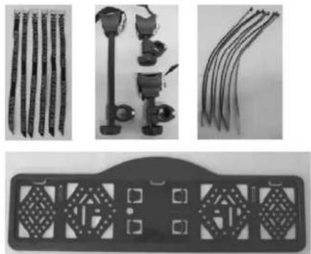
natural_image
Product display of mechanical components including rods, clamps, and a decorative plate (no visible text or symbols)Mounting:
Loosen and remove the little screws intended for the mounting of the number plate holder from the light holder rail and fasten the number plate holder to the rail. The number plate holder has to be level (or just above) with the lighting. Attention: The fastening clips to secure the number plate are incorporated in the number plate holder and can be pressed out.
With the provided cable ties, the light cable can be fastened neatly at the bottom of the carrier. Make sure the cable will not interfere with the tilting mechanism.
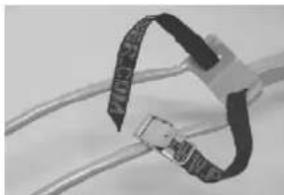
Slide the six short, black straps through the little slots in the wheel holder, starting inside-out, going around the wheel holder and then outside-in (see picture).
natural_image
Close-up of a black plastic clamp securing wires (no text or symbols visible)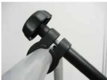
natural_image
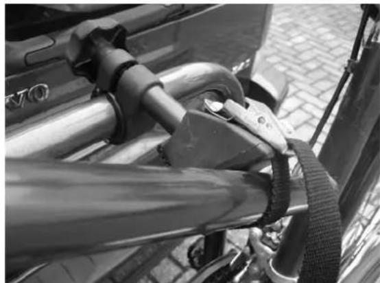
Close-up of a black tripod-mounted camera mount with adjustable grip (no text or symbols visible)Unscrew the plastic rotary knob of each frame holder, so the clamps can be folded open. First attach the rubber ring around the U-frame and put the clamp around it. Subsequently, re-attach the holder and screw the plastic rotary knob until you can just turn the frame holders (the frames of the bikes have to be attached to it, so they have to be movable). The sides with the straps are intended to fasten the bike.
End result:
natural_image
Mechanical device with labeled 'SAFFIER 3' on its side, no visible text or symbols on the device itselfMOUNTING OF THE BIKE CARRIER ONTO THE HITCH BALL
When mounting the bike carrier to the car, it is best that the car is parked straight, the engine is turned off and the parking brake is activated. Make sure that the hitch ball is undamaged, clean and not greasy!
natural_image
Black-and-white photo of a small electronic device with a metallic casing and accessories, placed on a textured surface (no visible text or symbols)The bike carrier can be mounted with the coupler on the hitch ball of your car. Slightly tighten the big bolt (M16x90). Check if the carrier runs parallel to you car (or bumper of your car). Next, tightly screw the bolt down with the supplied key until the carrier can no longer move on the hitch ball.
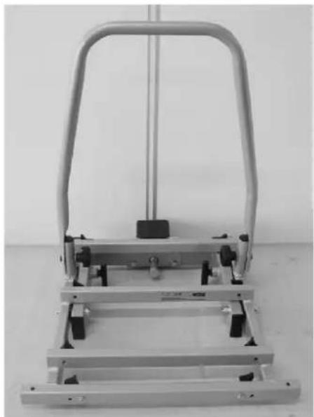
TILTING MECHANISM
For easy access to the boot of your car, even if the bikes are mounted on the carrier, you may use the tilting mechanism.
The bike carrier has two locking pins to secure the tilting mechanism. To tilt the carrier, you rotate the two locking pins by a quarter turn so the handles are horizontal. Subsequently you pull out the two pins. With one hand, keep a firm grip on the frame or the bikes, so that the carrier cannot fall down in an uncontrolled movement. It is now possible to tilt the carrier.
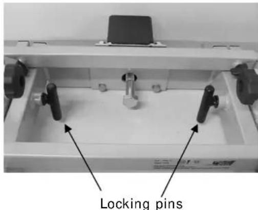
text_image
Locking pins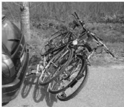
natural_image
Black-and-white photo of a pile of bicycles parked on a roadside, with a car partially visible in the background (no text or symbols)To secure the carrier again, you have to lift it and push the two locking pins back in. Subsequently you rotate the pins again by a quarter turn so the handles are vertical with the long part downwards. You will hear a click once they are secured.

Make sure that both locking pins are secured before you continue driving!
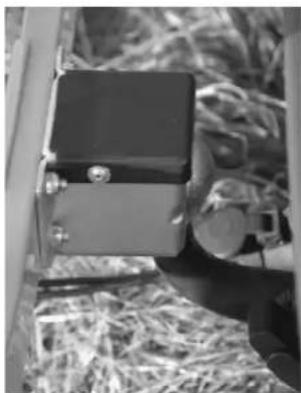
THE LICENSEPLATEHOLDER
The clips (2) to mount the license plate can be pressed out and are in the license plate holder (see picture).
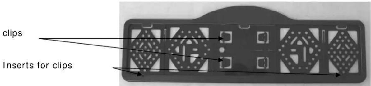
text_image
clips Inserts for clipsLIGHTING
This bike carrier is equipped with a lighting system. This system can be connected to the hitch ball power socket of your car. Seeing that there are
different kinds of sockets that require different kinds of plugs, this carrier comes with the usual 7-pin plug and the 13-pin plug (Jaegers). As a result, the carrier can be used with any hitch ball!
Both plugs are in one housing. Please cover the plug you don't use with the supplied cover.
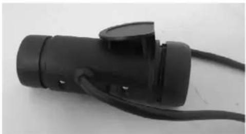
natural_image
Close-up of a black automotive plug with attached cable (no visible text or symbols)Universal system 7 pin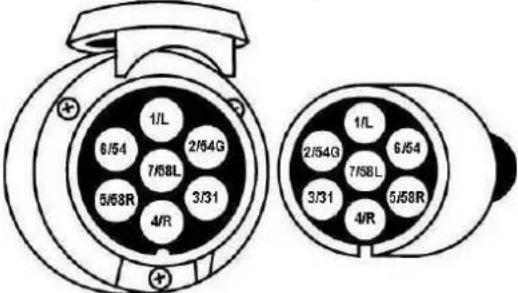 | 1/L2/54G3/314/R5/58R6/547/58L | Indicator leftRear fog lightGroundIndicator rightRear light rightStop lightsRear light leftThe reversing light is not working via the 7-pin plug! | yellowbluewhitegreenbrownredblack |
Jaegers system 13 pin(DIN 72.570)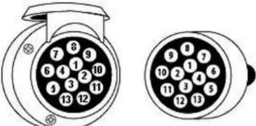 | 12345678910111213 | Indicator leftRear fog lightGroundIndicator rightRear light rightStop lightsRear light leftReversing lightNot usedNot usedNot usedGroundNot used | yellowbluewhitegreenbrownredblackgray |
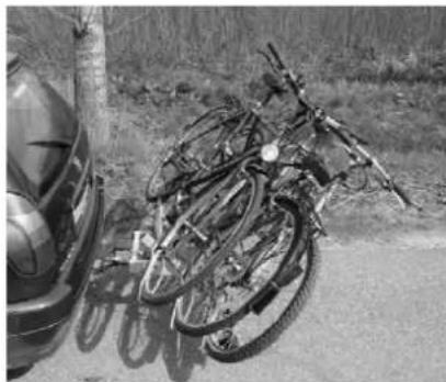
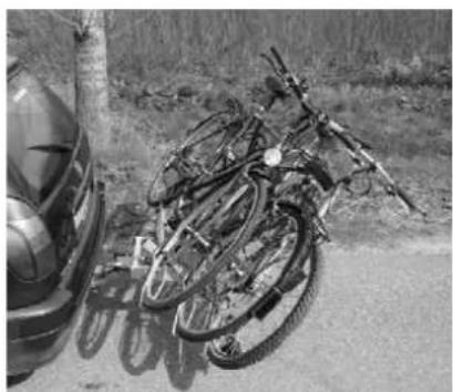
MOUNTING OF THE BIKES ON THE BIKE CARRIER

Remove all parts from the bikes that could easily be lost (E-bike batteries, bike pumps, speedometers, baskets, panniers, bicycle seats etc.) during transport. These parts may become loose by the increased air resistance and vibration and put other road users at risk.
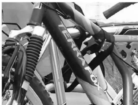
The first (and heaviest, max 20kg) bike has to be placed in the rear wheel holder (the one which is the nearest to the car) and secured with the short frame holder on the U-tube.
Adjust the wheel holders by pushing them in or pulling them out in such a way that the bike's wheels are inserted in these holders as symmetrically as possible and as far as possible. Attention: Do not pull out the wheel holders beyond the red mark! Use the straps to tightly secure the wheels to the wheel holders.
natural_image
Close-up of bicycle wheel hub with visible wiring and mechanical components (no text or symbols)Secure the bike frame to the U-frame using the frame holder. Since the frame holders do not have to be used in a fixed point, you can try out several positions. It is important to place the frame holders as high as possible. Use the straps to secure the bikes. With these straps, any bike can be secured easily without placing a load on the bike crank!
natural_image
Close-up of a bicycle support system with metal railings and a strap (no visible text or symbols)Place every next bike in opposite directions into the other wheel holders and proceed as described above for the first bike.
Now secure the bikes using the long safety belt. Run the safety belt through the bike frame and around the U frame and tighten firmly.
natural_image
Close-up of a motorcycle's front suspension system with visible hoses and exhaust pipes (no text or symbols)SAFETY REGULATIONS
Keep the hitch ball clean and free of grease.
Each time after having mounted the carrier on the hitch ball, it will "settle" during the first kilometres that you drive. Therefore, check if the carrier is still firmly secured after the first few kilometres and if necessary, tighten the locking bolt.
Check the bike carrier before use if there is any damage. Damaged or worn parts need to be replaced immediately. Only use original replacement parts.
Do not make any modifications on the bike carrier (mechanical or electronic) This can be very dangerous. Warranty claims will not be accepted and we can not guarantee the correct functionality of the bike carrier, if you done modifications. We are not responsible for damage caused as result of incorrect assembly, installation or modification.
Check the correct operation of the lighting at regularly.
Always make sure that the bikes are firmly fixed by using the frame holders and wheel safety belts.
Always use the extra safety belt, for extra protection of your bikes. Run the safety belt trough the U-frame and the frames of the bikes, and pull this firmly.
Make sure that no parts of the bike can get lost during driving (E-bike batteries, pump, basket, saddlebags, etc.). Always remove these before driving!
Check regularly if all the belts, knobs and fixations are firmly secured and if necessary secure them again.
Always make sure that the tilting mechanism is locked.
Do not cover the bikes with a cover while driving.
Driving with a bike carrier affects the performance of your car. Adjust your speed accordingly (max 120km/h). Try to avoid sudden braking and steering movements.
Please remember when driving in reverse that the car is longer than usual!

natural_image
Close-up of a mechanical lever mechanism with a spherical pivot and control panel (no visible text or symbols)In addition, pay attention to the regulatory requirements applicable to the transport of goods at the back of your vehicle.
When you have a vehicle with electronic parking sensors, an error message can come when the bike carrier is mounted. Switch off the parking system during the use of the bike carrier.
If the car is equipped with an automatic opening of the trunk, this must be switched off or only opened manually, if the bike carrier is mounted.
Take the bike carrier of the hitch ball before using the carwash.
The bike carrier is not suitable for "off road" use.
Take the bike carrier of the hitch ball if not used.
In case of defects or problems please contact your Pro-User supplier.
MAINTENANCE
Always store the bike carrier clean and dry after use. If necessary spray with the water hose to remove mud and other filthy stuff.
Keep the hitch ball of the car clean and free of grease.
Keep the connector of the bike carrier clean and free of grease.
Check the bike carrier regular if there is any damage. Damaged or worn parts need to be replaced immediately. Use only original replacement parts.
The nuts and bolts of the bike carrier need to be checked regular, if necessary tighten them again.
If there is a damage on the powder coating of the bike carrier, this needs to be treated with paint immediately.
Rotating and moving parts need to be oiled regularly.
GUARANTEE
This product is covered by a 2 year guarantee. Please note that our guarantee covers reasonable use of the bike carrier, it does NOT cover any damage caused by misuse. This also applies to a malfunction or failure of the bike carrier that has been caused by poor or incorrect installation. To ensure the validity of the guarantee please carry out maintenance in accordance with the maintenance section. We reserve the right to make a call out and/or repair charge for any work required to be undertaken to rectify faults that are outside of the company's control i.e. incorrect or poor fitting, misuse, accidental damage, etc.
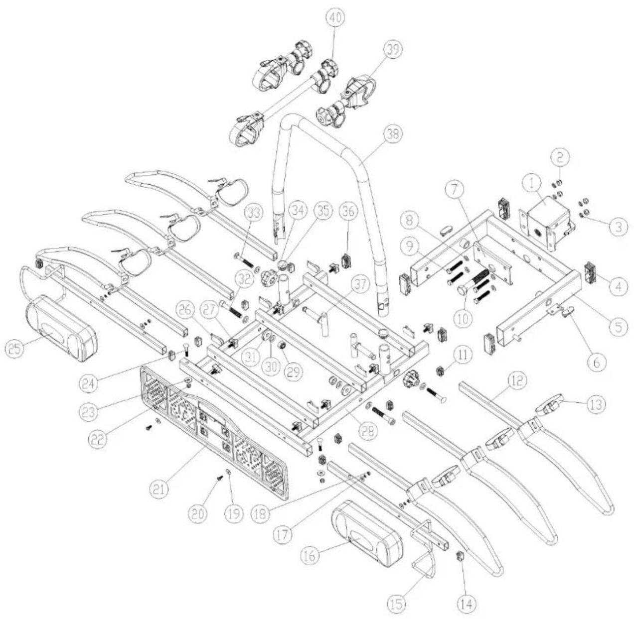
PARTS LIST
| Pos nr. | Description | QTY | |
| 1 | Coupling 1 | ||
| 2 | Self-locking nut 4 | M8 | |
| 3 | Lock-washer 4 M8 | ||
| 4 | End-cap 4 60×25 | ||
| 5 Inner base frame 1 | |||
| 6 | End stop 2 | ||
| 7 | Mounting plate 1 | ||
| 8 | Washer 4 M8 | ||
| 9 | Hex head bolt 4 | M8×45 | |
| 10 | Hex head bolt | 1 M16×90 | |
| 11 | End-cap 6 25×15 | ||
| 12 | Wheel holder | 6 | |
| 13 | Straps | 6 | |
| 14 | End-cap | 4 | 25×15 |
| 15 | Lamp holder | 2 Right = left | |
| 16 | Lamp(right) | 1 | |
| 17 | Washer | 4 | M5 |
| 18 | Self-locking nut | 4 | M5 |
| 19 | Washer | 2 | M5 |
| 20 | Small screw | 2 | |
| 21 | License plate holder | 1 | |
| 22 | Self-locking nut | 2 | M6 |
| 23 | Washer | 2 | M6 |
| 24 | Carriage bolt | 2 | M6×40 |
| 25 | Lamp(left) | 1 | |
| 26 | Stainless steel wheel holder clip | 6 | |
| 27 | Plastic knob | 18 | M6×12 |
| 28 | Outer base frame | 1 | |
| 29 | Self-locking nut | 2 | M10 |
| 30 | Washer | 4 | M10 |
| 31 | Plastic washer | 2 | M10 |
| 32 | Socket head screw | 2 M10×65 | |
| 33 | Carriage bolt | 2 | M8×60 |
| 34 | End-cap 2 | ||
| 35 | Plastic knob | 2 | M8 |
| 36 | Plastic end-cap | 2 | 40×20 |
| 37 | Locking pin | 2 | |
| 38 | U-frame | 1 | |
| 39 | Shorter frame holder | 2 | |
| 40 | Longer frame holder | 1 | |
Remark
text_image
Exploded view diagram of a device's internal components with numbered parts for identificationINTRODUCTION
natural_image
Black SUV with bicycles parked in front, no visible text or symbols on the vehicles or background

natural_image
Close-up of a laboratory apparatus with metallic fittings and a central dial (no visible text or symbols)natural_image
Mechanical assembly frame with metal components and mounting holes (no visible text or symbols)Etape 2
Eléments:

natural_image
Mechanical frame assembly with metal frame and mounting brackets (no visible text or symbols)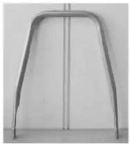
natural_image
Metal frame with rounded ends and vertical centerline, no visible text or symbols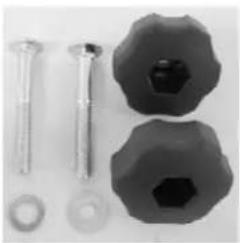
natural_image
Assorted mechanical components including screws, bolts, and a hexagonal nut (no text or symbols visible)L'assemblage:
natural_image
Close-up of a mechanical device with a black handle and metal bracket (no visible text or symbols)Résultat final:
natural_image
Mechanical device with metal frame and handle, no visible text or symbolsEtape 3
Eléments:

L'assemblage:
natural_image
Close-up of a mechanical component with two metallic clips and a central hub, showing alignment arrows (no text or symbols)natural_image
Mechanical assembly with metal frame and multiple levers (no visible text or symbols)Etape 4
Eléments:
natural_image
Mechanical device with articulated arms and wiring, no visible text or symbols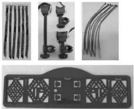
natural_image
Product display of four different types of hair accessories and a decorative tray (no text or symbols visible)L'assemblage:
natural_image
Close-up of a coiled cable with black bands and connectors (no visible text or symbols)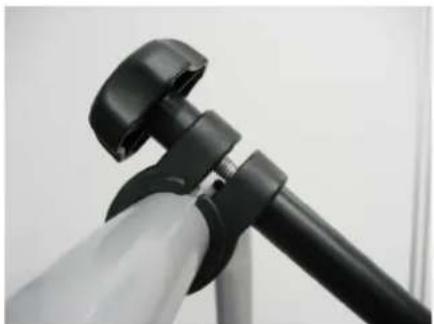
natural_image
Close-up of a black and white tripod-mounted device with adjustable grip (no visible text or symbols)natural_image
Mechanical robotic device with labeled 'SAFFIER 3' on the front, no visible text or symbols on the device itselfMONTAGE DU PORTE-VÉLOS SUR L'ATTACHE-REMORQUE
natural_image
Close-up of a mechanical device with attached components, possibly a tool or device, in a warehouse setting (no visible text or symbols)natural_image
Interior view of a laboratory apparatus with labeled components and directional arrows (no readable text or symbols)les goupilles
natural_image
Black-and-white photo of a bicycle with broken tires and a tire beside it, parked on a roadside (no visible text or symbols)natural_image
Black electrical plug with attached cable, no visible text or symbolsnatural_image
Close-up of a bicycle wheel assembly with visible blades and suspension rings (no text or symbols)natural_image
Close-up of a bicycle's seatbelt and chain strap mechanism (no visible text or symbols)natural_image
Close-up of a motorcycle's front wheel and suspension system (no visible text or symbols)CONSIGNES DE SÉCURI TÉ
natural_image
Close-up of a mechanical lever mechanism with a spherical head and control panel (no visible text or symbols)text_image
Exploded view diagram of a device's internal components with numbered parts for identification© Tradekar 91535/15A

text_image
PROUSER BIKE CARRIERS® USERTradekar Benelux BV
Staalweg 8 +31 (0)345-470990
4104 AT CULEMBORG info@tradekar.nl
The Netherlands www.pro-user.eu