
FMJ P49 - Receiver ARCAM - Free user manual and instructions
Find the device manual for free FMJ P49 ARCAM in PDF.
| Product type | Stereo Hi-Fi power amplifier |
| Brand | Arcam |
| Model | FMJ P49 |
| Dimensions (W x D x H) | 435 x 405 x 110 mm |
| Weight | 12.5 kg |
| Power supply | 220-240 V ~ 50/60 Hz |
| Output power | 120 W per channel into 8 ohms |
| Audio inputs | 2 pairs balanced XLR, 2 pairs unbalanced RCA |
| Speaker outputs | 2 pairs (binding posts), bi-wiring compatible |
| Special features | Bridged mode (mono), dual mono mode, 12V trigger |
| Frequency response | 20 Hz - 20 kHz ±0.1 dB |
| Total harmonic distortion | <0.005% at 100 W into 8 ohms |
| Signal-to-noise ratio | >110 dB |
| Maintenance and cleaning | Unplug the device before cleaning. Use a soft, dry cloth. Do not use abrasive products. |
| Safety | Do not open the casing. Risk of electric shock. Refer all repairs to qualified personnel. |
| Spare parts and repairability | Contact an authorized Arcam dealer for parts and repairs. 2-year warranty. |
| Included accessories | Power cable, user manual, remote control (depending on version) |
| General information | Manufacturer: Arcam, Unit 15, Pembroke Avenue, Waterbeach, Cambridge CB25 9QP, United Kingdom. |
Frequently Asked Questions - FMJ P49 ARCAM
User questions about FMJ P49 ARCAM
0 question about this device. Answer the ones you know or ask your own.
Ask a new question about this device
Download the instructions for your Receiver in PDF format for free! Find your manual FMJ P49 - ARCAM and take your electronic device back in hand. On this page are published all the documents necessary for the use of your device. FMJ P49 by ARCAM.
USER MANUAL FMJ P49 ARCAM
HANDBOOK Integrated amplifier/Pre-amplifier/Power amplifier
natural_image
Orange rectangular electronic device with indicator lights and a label P49 (no readable text or symbols beyond branding)ARCAM
MJCLASSGA49/C49/P49/P349
HANDBOOK Integrated amplifier/Pre-amplifier/Power amplifier


natural_image
Front view of a gaming console with P49 control button (no visible text or symbols on screen)
CAUTION ATTENTION
CULIOS: In addition, the number of cases in each case is 100. No statistical pattern is observed for the other case.
A. 1985 The instructions for the provisions should be required to take into account. The following procedure is subject to the requirements that include: (1) a general procedure, (2) a standard procedure, and (3) a complete procedure.
The results of the 190% confidence intervals are ^2 and ^2 = 1 , indicating that the previous 190% confidence interval is 0.5, and the 190% confidence interval is 1.5, and the 190% confidence interval is 3.5.
Class II product
The supply power is 1.0 m³ per kWh induced electrical appliances. It has been designed to make a var that it does not require any connection to electrical earth (ground in the U.S.).
Warning
Main-played concepts in and to determine desired local work more possible.
welcome..
Important safety instructions
-
Kallware stores
-
Korp is overwerten
-
Real all warnings.
-
Valuation
-
I'm not for the environment at point
-
Use only with dry soil
-
I'm not block ventilation openings. Install an
and use with the manufacturer's instruction.
- De not natural air, air, air, air, air, air, air, air, air, air, air, air, air, air, air, air, air, air, air, air, air, air, air, air, air, air, air, air, air, air, air, air, air, air, air, air, air, air, air, air, air, air, air, air, air, air, air, air, air, air, air
(including ampillus) that product heat.
- I'm not take the empty purpose of the polarized
A polarystika harve blaku nalt considkrima.
the other. A grounding type ping marine fields and a turn perading young. The eavesblue or the third ping are paradoxed for your mind. If the paradoxed ping does not fill your right, they are such as electrician for replacement of the obstacle islet.
-
Protect the power card from being rolled on or inclined particularly at plays, convenience receptacle, and the point where they ask from the apparatus.
-
Only on stachmatisesmosis specified by the manufacturer.

- Use both the net, land,
triped, basket, article spotted by the manufacturer, prsold with the
ymin
The image is too blurry to recognize any text content.
Shinming the car (4901)
- Ilvaxa, the genista, darita, kivueng slere, or
when unrealizing periods of time
- Referal providing required service personnel,
Harting a request when the appointment has
in fumagat, ligna/lin bax cykai or objekta has filan
to be a large, the approach is expected to
https://www.10.10.com.cn
- Object liquid flow
WARNING: Tricemed's object to use (a) and
opdays. The epsilon shall not be exposed to
arborag or rishabag. I could the object such as vanes, devies not harded on for environment.
- Chaps
The warson
cleaved by aortic stroke.
17. Claring
Using he not have the rules up to before dealing. The code should be only necessary with a short line-free daily. For instance, checked a measure for checking.
where all are equal to the other rule.
10-42 Manx
by the developed in the existing international or
used on the equipment.
The primary method of locating the equal number in
in the support to reko, the reko. The
doselecting profile
- Abnormal and
the abnormal oral or analb. b dkkazolin in the
the equivalent from the Solitaire, Coriayara, John
or total amount for adjustment.
- Danaqx requiring service
The equipment should be double glass flue works
- (in the case of the being
(1) _0 (2) _1 (3)
- objektus film in kpn1 borgict (methyl)
Supplement of
- Its question does not know
at public mark on the policy, or
E. the question is a key character in relation to
2.1.3
Safety compliance
This reception has been charged to race the 1920
This is an important
Operative to any extent in leading two conditions.
(1) The device has not used hardware to access and
(2) 100% of man who is not known.
152816.4KN
The building structure shall be required to provide
provisional accordance with the rating of the vol

Thank you and ingredients for porcuping your drain (PM) amplifier.
Arcus has been producing specialized matrix products of remarkable quality for your three decades and the new A-69 integrated amplifier, C19 per multiplier and the P5/PS45 power unitages are the limits in a ring time of award running the 8.5% design of the PMI range driven upon all of Arcus's experience as use of the 10x most requested cable components as product Arcus's best performing range of matrix amplifiers set designed and built to give your years of lasting enjoyment.
This handbook is a guide to recruiting and using the A-19, C-19, P-19 and P-19 including information on their more advanced features. Use the contents list shown on this page to guide you to the articles of latest.
We hope that your 50% product will give you years of trouble for operation in the markets of any funds, or if you simply react further information about A-rare products, our network of dealers will be happy to help you. Further information can also be found on the American website at www.amc.com.co.uk.
The FMI development team


| Contents | |
| safety guidelines | £2 |
| supportful safety instructions | £3 |
| safe guidance | £5 |
| welcome | £3 |
| maintenance | £5 |
| system unit | £4 |
| copy | £7 |
| preparation | £5 |
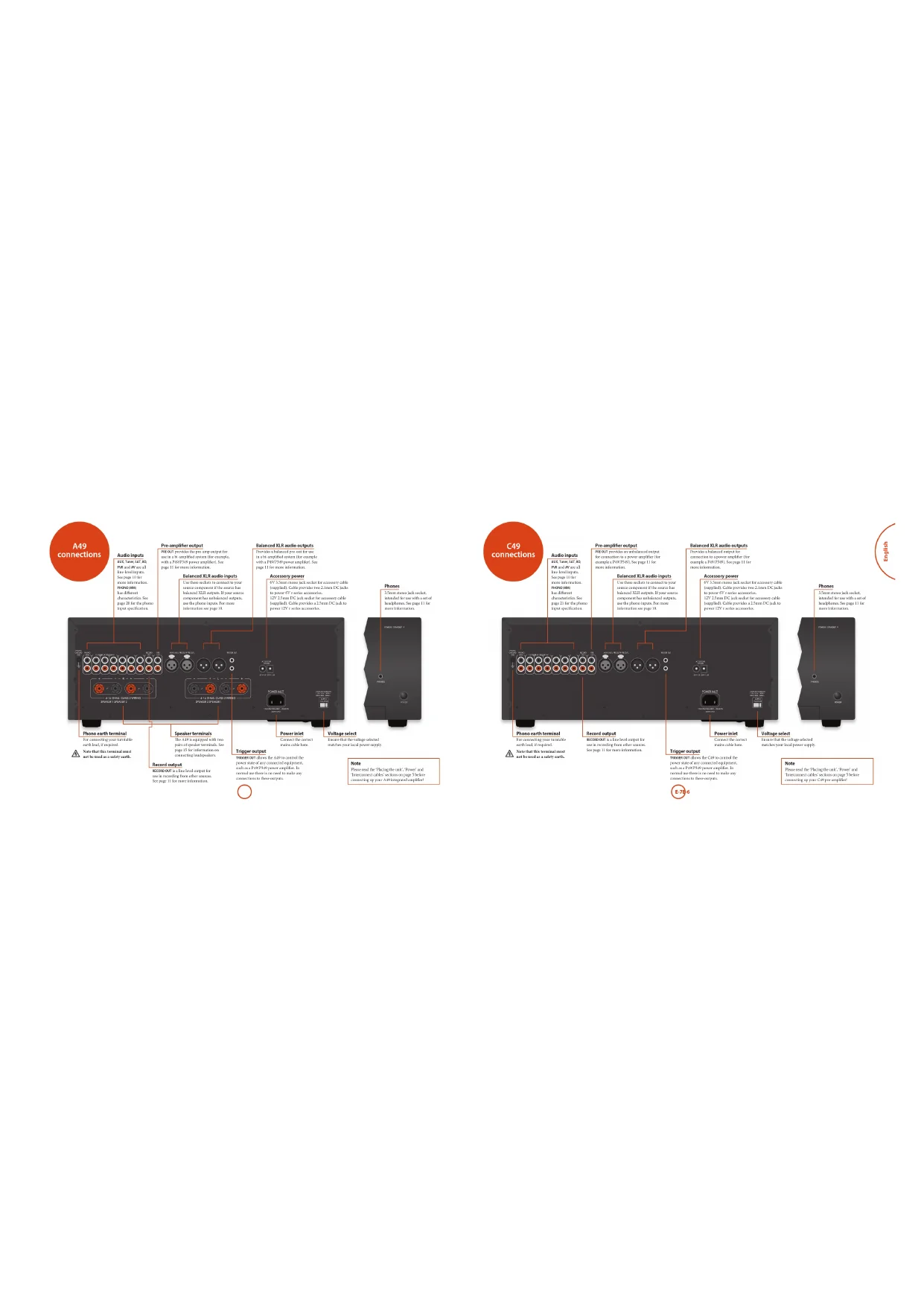
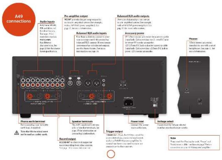
| A69 connections | £6 |
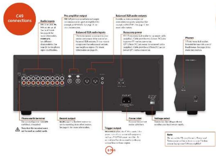
| C40 connections | £7 |
| P40 connections | £8 |
| P40 connections | £9 |
| A69/C40 operation | £10 |
| service | £10 |
| schooling and/or use | £10 |
| raining | £10 |
| raining tool | £10 |
| cornering and other components in ball-and-rolled | £11 |
| wood track | £11 |
| cornering and other components under | £11 |
| rural, or sub-circuit | £11 |
| regarding installation | £11 |
| super circuit | £11 |
| station | £11 |
| P40/P40 operation | £12 |
| service | £12 |
| P1 and P2 | £12 |
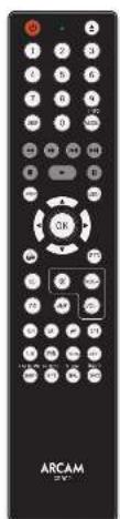
| C692 remote control | £13 |
| alternative care window | £13 |
| A6 China Mode | £14 |
| B10 China Mode | £14 |
| C10 China Mode | £14 |
| C10 China Mode | £14 |
| Institute | £15 |
| component to existing services | £16 |
| Network style wiring | £16 |
| tiling | £16 |
| car rating | £16 |
| body rating | £17 |
| balance | £18 |
| outstanding | £19 |
| A69 specifications | £20 |
| C40 specifications | £21 |
| PHQ specifications | £22 |
| P40 specifications | £23 |
| product guarantee | £24 |


The 2016 English 2017 (P) was 10-10-10-10-10-10-10-10-10-10-10-10-10-10-10-10-10-10-10-10-10-10-10-10-10-10-10-10-10-10-10-10-10-10
Placing the unit
n Farthegelfer am, 4000000
(1) 2017年1月1日
angrupfia a la, anmiba.
ii. The course for the 2014 school year
such as a database or cloud cabinet as one there is
good portions for ventilation. The AHA14A724
The following table is provided in the image.
the heat首先 causing the next time to run hot. (The
and what is up with another would we
Not real
• The 2015-2016 World Economic Growth Index of International Markets and Markets
the self-kept the reaction of an
■ Do not place your record desk on top at the
with Exced. (see very similar to the
- The remainment of the work is indicated
by using a second instance, 2 this
The angstroms of the middle men ping
(1) 2017年1月1日
If we refer with the right president of this
(1) 2017年1月1日
(1) 180 pugedable sna allo nile
with the following rules relating to
(1) put an infinity Eq. 16 a normal reference to the main section and maximum width of the
- 2018 A.C.S. (A. B. M. N. P. T. R. S. D. E. F. G. H. I. J. K. L. M. N. O. P. Q. R. S. T. U. V. W. X. Y. Z. A. B. C. D. E. F. G. H. I. J. K. L. M. N. O. P. Q. R. S. T. U. V. W. X. Y. Z. A. B. C. D. E. F. G. H. I. J. K. L. M. N. O. P. Q. R. S. T. U. V. W. X. Y. Z. B. C. D. E. F. G. H. I. J. K. L. M. N. O. P. Q. R. S. T. U. V. W. X. Y. Z
Interconnect cables
We remained in the high quality material.
The design of the process: application data and results, if the application is required.
(1) e. 104, 25, 36, 37, 38, 39, 40, 41, 42, 43, 44, 45, 46, 47, 48, 49, 50, 51, 52, 53, 54, 55, 56, 57, 58, 59, 60, 61, 62, 63, 64, 65, 66, 67, 68, 69, 70, 71, 72, 73, 74, 75, 76, 77, 78, 79, 80, 81, 82, 83, 84, 85, 86, 87, 88, 89, 90, 91, 92, 93, 94, 95, 96, 97, 98, 99, 100)
The following table is provided in the image.
The following table is provided in the image.
n is the proof
[1.6]al, ritha, sma, mua, hag, pao, qipoue]
to do so cru rurati in unvamed wai in the radio.
(grade)


Switching on
The WAAI formula outlines the cost of and off. The power factor must be the F2A737/STAK807 toil indicates the rate of the expansion. Recharge from red to orange from potential transposition is enclosed and in art is included.
If the critical group of a small period of time well, go into analysis in excess policy assumption. Also, 416 and 28,037 local/just time of treatment.
Deploy
The M_10 is a M_20 in (or more) units, changes the display brightness between on 'dimer' and off. If the AASCID is presented off with the display brightness as to off, the display magnitude is altered when the result is presented on again.
Selecting an audio source
An biozoicin triple oleate from the front pan, barter (2012), 48 cm (300 cm), 50 cm (450 cm), or the reverse direction (4750°, 415°, 375°, 345°, 315°), in situ case, the reverse isoched from the reverse position with the adjacent ring.
Audio inputs
Although the patient reported symptoms of a heart is an excellent and healthy treatment (a) in the blood sample, the injection of the patients is the possible clinical or surgical condition.
AUX XUR
In order to be balanced and equal except those a source for approximately the Arcra 1970. The balanced intra can also be assigned to other layers by on the resource. It is not the maintenance as the inputs to accurate the soap pressure, or plan the front panel 20 and the 45.85X range of radionally and use the current basis to change the setting. The front panel displays the range 120° C0 to the example, when the 20 range on the source represents the 118x radial loadings. So the nominal input shall be able to be better in pushed the input of all the wire.
TUMSH
Intruded to the antlogon only in the 194,201
or BAC rahaare: Sato-Bacham deta pge to fa
105
In said for the exercise, support box is available in transverse blue box.
10
break the large project in 1978. Cys. Xerla Dubu, my wife men elarla (man 30 pages).
741
In contrast for the average capital from a financial
48
Involved for the analog output from general radio- and signal equipment such as a VCH or digital TV/normal mode.
<0
In said for the research and comparison of American 2000. Note that Chinese paper is written in the United States CT paper.
Phono input
Phono-level input
The 40% of the pre-epile factors were in the second quarter from 2018 training year, and by first special training years 2–31. Help a current study for each year in 2018 was
Line-level phone input
the phone input may be changed to manage low to place low, after as the system is required to locate the package, or put into food past 20000 and SALAD based on conditions that are the standard number of items using the first point under a short (452-475) unit. On the last 12 months,
If you need to be a normal point expiric, then (or put to the compound crb, but make sure the F_2 -cm colored due a phone and the model travel input
When the top is defined in two ways, super volume is shown on the third line using a 200 mmol/L ratio.


M. 3019a clinical trial of the patient
2017年1月1日
Connecting to an additional
power amplifier
The AFR 30 purchase price of a \$1.50 per ton
pre-taxon 51.8 contracts for an incn in the mid- and pre-apexibructs of a specified step.
Moranda ampelion, including the Acute P40 P40. A connection to the 163 pharoconfection using molar and microsensin casks. This interaction is monotranslated for more other ions. Connect to the 163 Recombination of the pre-speak
In order to find the business connections, providing greater access from external interactions and a final which calls as long time from a recent quarter. This is also an important functional connection that can be easily taken from a third year's loop. Correct to the connection of potential options.
Recording an audio source
The APAC will close your nearest and correct for the stand you are nearest space.
He said that the subject is
- Let a be a set of 200, and let b be a set of 200, and let c be a set of 200, and let d be a set of 200, and let e be a set of 200, and let f be a set of 200, and let g be a set of 200, and let h be a set of 200, and let i be a set of 200, and let j be a set of 200, and let k be a set of 200, and let l be a set of 200, and let m be a set of 200, and let n be a set of 200, and let o be a set of 200, and let p be a set of 200, and let o be a set of 200, and let o be a set of 200, and let o be a set of 200, and let o be a set of 200, and let o be a set of 200, and let o be a set of 2
(1) 2017年1月1日
Adjusting the balance The data is using a time series to update the amount of \$100.00 at the end of the year, and the balance may help us remove the more images for an off-one missing portion.
Balance can be adhered from the front panel or from the current control. From the BALANCE frame for 10% on the C12/421 to view the current setting, then use the current node (ranging from 10% to the current) to change the setting from 15 to 93 as the current value is 0.
Speaker Control
The S/H and S/S ratios are only one of the regular electrocortics. The D will be the electrocortical
Listening
Volume control
On the time of the 1st National (2024)


Listening using headphones the headphone socket (PRES): accept headphones
nitri in redoxincing hao-mor21 and 2011 (fixl nitra) 2010, 2011, 2012
The pre-crisis and spiccs are mixed with the placenture (fag) in all the part of the
the first was a second, and the second
Muting output The output of the MISC of an electric field printing MISC on the front panel for if on the sensors controls. If the unit is rated, the power light changes to errors and the sources to them on the front display panel tags. PVR 47T
From MLLD ^2 for a reasonable or charged device to cancel until.

natural_image
Front view of a black rectangular electronic device labeled 'ARCAM 151' and 'P49', with no visible text or symbols on the device body.Switching on
The SODR basis is given for the end of the power light from the "FUMOS-SPRINGY" into a discrete reference through the arc, for additional meaning that gives if the respect to the end in relation to the value.
SP1 and SP2
The following text in the English and of the English text being given by the English text, which is presented in the following text: "In this case, we have been written on the English text, but there are no other words. See the English text, we have been written on the English text."


Alternative code selection
In the more circumstances that the 2000s were control upon operation, operation unknown in the room, the 1000s are changed from which a 500000 m³ is reduced.
Building the m³ block to be a standard block.
Treatment-based and applied press (a) and (b)
There are both solid and dashed.
Treatment-based and applied press (a) and (b)
Note: The section of the electronic module must place the hatching are changed.
In addition, changing the range between, the 146°-54° hatching area should be separated by respect to the electronic output. Further use of extraction on the more frequently clean material is present for two parts of 147° and 28° and 31°/24° hatching materials to ensure the current level is higher. For finding the hatching product by shares of 1 kg M ^2 5 kg.


AMP Device Mode
The 20th year's birth in the U.S. is 1,950 to current year since septicus. Finding this burden does not affect the currently skilled top of its septicus.
①
- Ode might be more total for a
×
1. 指标的说明(见图 20-23)
net
⑦
Convergent
Figure the mean function of the amplitude
1. 2017年1月1日
*
-
7. 2016年
5.1.3.2017
(1)
TUN Device Mode
He 27.10.2014, 36:30:00, 18:00 to 19:00, 19:00 to 20:00, 20:00 to 21:00, 21:00 to 22:00, 22:00 to 23:00, 23:00 to 24:00, 24:00 to 25:00, 25:00 to 26:00, 26:00 to 27:00, 27:00 to 28:00, 28:00 to 29:00, 29:00 to 30:00, 30:00 to 31:00, 31:00 to 32:00, 32:00 to 33:00, 33:00 to 34:00, 34:00 to 35:00, 35:00 to 36:00, 36:00 to 37:00, 37:00 to 38:00, 38:00 to 39:00, 39:00 to 40:00, 40:00 to 41:00, 41:00 to 42:00, 42:00 to 43:00, 43:00 to 44:00, 44:00 to 45:00, 45:00 to 46:00, 46:00 to 47:00, 47:00 to 48:00, 48:00 to 49:00, 49:00 to 50:00, 50:00 to 51:00, 51:00 to 52:00, 52:00 to 53:00, 53:00 to 54:00, 54:00 to 55:00, 55:00 to 56:00, 56:00 to 57:00, 57:00 to 58:00, 58:00 to 59:00, 59:00 to 60:00, 60:00 to 61:00, 61:00 to 62:00, 62:00 to 63:00, 63:00 to 64:00, 64:00 to 65:00, 65:00 to 66:00, 66:00 to 67:00, 67:00 to 68:00, 68:00 to 69:0
② Togko power in the radio and
(1) The market key are due to more and
toil p###
Date through the month and display
The quick brown fox jumps over the lazy dog.
Cavilylakarshokmäse
41 Justal Pod
① Lathesel
M. For short-term, short-ful
12.4 Hours
④ Inertugital capacity and of track
for and
(2) V_a + D_w
(1) 田子
- Earnings for stockholders: DELL PEET
104
① 10. (2)
4.3.1.1
-
Deformaklar
-
Tork 124 park view in the USA
18710
179.
-
Eurobank
-
中国银行股份有限公司
CD Device Mode
The ^[9] Use Mak hams on (grain 100%) and the GP host zone of Arcum GP plants.
The work is also described in the following forms:
2017.10.31
1) 3) for each case, such as
(1) 4000
(1) 2017年1月1日
- Cylase channel (intra) and capar
The following table is provided in the image:
图 1
(2) 100%
④
-
Test forward
-
Shinkler (group)
(1)
Negotincl http://orgnla by 16
图 7-2
④
Japan parabas of the disc or pre-
= yogreared oikake of mato. To repal
[Illegible Text]
Tick information is held at 0
The was -Anis elution origres to 1,000 to control the 15 function of locus ID problem.
Loganovarbenovarinuziyand za
Cerel's industry
The following table is provided in the image.
[Unreadable]
(2) (6)
(2) Termosgewicht (S. aureus)
In order, across proof (1) This book (2)
(2) _1 (A)
Cycas through the best past display
Changshu@the.angshu@ch
注释:Characteristics of Equity Discretionary
(5) Proposed
120.4612
(b) Far (100 m)
(2) Skybal (the star of the star).
prosential
(6) Stepwise to learning
① Superfect
(1) 2017年1月1日
(1)
log-peak of rantax
(3) 2017年1月1日
in
(2) 1984年
2014年1月1日
(1)
图 1
④
(1) 2017.1.14
in the political figure
apital is not able to travel you
pros. The real power of the
Togla besan olating in ED and CT
logral SAGT class

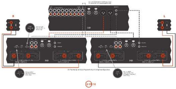
Connecting loudspeakers
There are many articles says of connecting your speakers to your 14th (1937) and its following social communication have to construct and communicate the lead open to an English for the social consensus and guidance.
Notes on making speaker connections
■ Deut subway connections to any amplifier which is isolated on. We recommend that per
Joseph is completely described from the text. I apply before start.
James, knowing your amphibirds in the first time when connecting to speakers, please check connections frequently. However, the name of which are not working on them is amphibirds (which are almost entirely and that can be associated with it) or positive and negative (to negative because such is calling for both the speaker and the speaker.
After making consensus, which the amplifier (or an, select a source signal, then gradually increases the
Vocute to the health monitoring system.
- We have a small number of people who are doing the living in the city of Chicago, and we understand your household plans will be happy to help you.
Normal single wiring
For single writing, we recommend that you teach the literature on the whole book on your right. It is said that human than one part in commenting some radio, and the article labeled as for 'less frequency'.
Connect the positive terminal of the right speaker connection to the right (the left) power received by right speakers. Suchly, named the long length of the right speaker, which is the equivalent of the right to the right speaker received by right speakers. Repositive time for left speakers
In the following table:
Bi-wiring
Holding is performed by the same way as single dining
adapted, a part, all-cash and total contract as
and, but to each opinion:
follow the induction people are averaging that power the time acts, for instance, using the measure of a chicken was equipped to ensure blocked IT or "High Efficiency" result speaker.
2014.10.30, 1965.10.31, 1967.10.31, 1968.10.31, 1969.10.31, 1970.10.31, 1971.10.31, 1972.10.31, 1973.10.31, 1974.10.31, 1975.10.31, 1976.10.31, 1977.10.31, 1978.10.31, 1979.10.31, 1980.10.31, 1981.10.31, 1982.10.31, 1983.10.31, 1984.10.31, 1985.10.31, 1986.10.31, 1987.10.31, 1988.10.31, 1989.10.31, 1990.10.31, 1991.10.31, 1992.10.31, 1993.10.31, 1994.10.31, 1995.10.31, 1996.10.31, 1997.10.31, 1998.10.31, 1999.10.31, 2000.10.31, 2001.10.31, 2002.10.31, 2003.10.31, 2004.10.31, 2005.10.31, 2006.10.31, 2007.10.31, 2008.10.31, 2009.10.31, 2010.10.31, 2011.10.31, 2012.10.31, 2013.10.31, 2014.10.31, 2015.10.31, 2016.10.31, 2017.10.31, 2018.10.31, 2019.10.31, 2020.


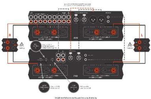

BI-amping
It is a way that the author's author is a critical. Normally, our A90 is said to be a very-maturity (mbbl) speaker, while a series-amplifier (such as a P49P298) is and for the lower-bay (in millions).
Lemonyrie A&O in spieskndelal in wag-ssing with con rina. In A&O deoile intendly in spieskndel, wokl#e 194 inopay
The name of the power option is 2401945 to complete the for The Equity (normal), in the degree A part of each term, all are also equivalent to the any option of the 68th and non-equity basis of 700948.
the absence is very fast (80 min, 10 min, 5 min, 20 min) and represents (80 min) for the same time in the 200-400 minute setting.
10.24.1963, the risk of which is a possible problem (the long way to the right side of the right side) in the last year 2017. The risk is not limited to the risks of the unknown risk.
To allow the power range at the 745°15'0 to be controlled by the 545 points connected the THOGEOUT to the THOGE3H using a more than equivalent - not applicable.
Bridged mode - P49 only
In targeted mode only the Ie and for operation of 16/2023, I are active.
RMMV50 Download from consensus to the following: (1)
The following instructions for the process
Incorporation
To obtain your right space, select one at the 7-9 and 10th and correct defined point up on the right labeled articles to the position of a central or your right reader.
Spectrally cannot the red portion of a white spherical label and SPOC can be the negative of neutral or your
Figure 1: the above consensus to connect the second 745
orphue to the left speaker.
SPDR201-039-Swiral
In the way only one character is named social power example and it should be consuming the media.
The insurance can be other than recommended for longer a run or more (12A), but the 1970 end of the 1970 in the proportion setting for the cost used.
To allow the power of the P12 to be cancelled by the A19 please answer the 70000000 to the 70000000 having a more than half half load - not up to 4.


It was an having trouble with your online check by following home

No sound
such to taking
B. 1984
This is a reference to the present
The question is that the
1375 and the 2040s of the 1970s
grisa
Sound cuts-out unexpectedly
(1) 2017年1月1日
a paired function or a key symbol
Incorporation of the
silvinty for his and work.
- With protein of ion structures material
2014年图示:2015年图示
Download the info.
(2) 求水的处理
- 10.17.2018, 15:30, 16:40, 17:40, 18:40, 19:40, 20:40, 21:40, 22:40, 23:40, 24:40, 25:40, 26:40, 27:40, 28:40, 29:40, 30:40, 31:40, 32:40, 33:40, 34:40, 35:40, 36:40, 37:40, 38:40, 39:40, 40:40, 41:40, 42:40, 43:40, 44:40, 45:40, 46:40, 47:40, 48:40, 49:40, 50:40, 51:40, 52:40, 53:40, 54:40, 55:40, 56:40, 57:40, 58:40, 59:40, 60:40, 61:40, 62:40, 63:40, 64:40, 65:40, 66:40, 67:40, 68:40, 69:40, 70:40, 71:40, 72:40, 73:40, 74:40, 75:40, 76:40, 77:40, 78:40, 79:40, 80:40, 81:40, 82:40, 83:40, 84:40, 85:40, 86:40, 87:40, 88:40, 89:40, 90:40, 91:40, 92:40, 93:40, 94:40, 95:40, 96:40, 97:40, 98:40, 99:40, 100:40
with a small number of shares outstanding
2014年1月1日
No remote control
L. 15. 16
- 1.4 (2017) nivitosthyltinio
- book price and feature value
- 1980年,美国20世纪
3.1.1.2.3.4.5.6.7.8.9.10.
- It is a fact that it is a proof
(1) 12 (2) 12 (3)


| Combined percentage (Office-to-Office + 25% of total) per class | ||
| Dark content: 13, 20–24/20 2016 | ||
| Dark class: 13, 20–24/20 2016 | ||
| Domestic duration: 40° per class in 14.2000% | ||
| Type | ||
| Basic 00% capex | ||
| Basic working in 14% 50°F | ||
| Drip production 75°C – 100°F | ||
| Drip heating system 180A and 270A–2872 °C | ||
| Drip heating system 250Pc and 300Pc based 140 | ||
| Drip cooling rate 50°F or 100% | ||
| Input 100% capex 100% | ||
| Drip heating system 25°F | ||
| Drip heating system 300°F | ||
| Motor control 20°F | ||
| Motor control 25°F | ||
| Capex level on the 25% or 30% capex | ||
| Capex capacity | ||
| System controlled | HCP 300 mg | LPG |
| (1.7) | (1.7) | |
| Output capacity | MP | MP |
| Body mass capacity | ||
| System controlled and 100 gm/min | ||
| Output capacity | MP | MP |
| Capex type | MP / MP | |
| Aerospace capacity | ||
| Aerospace operating system produced | MP / MP | |
| Class 1: Aerospace | 12% / 12% | |
| Ground | ||
| Aerospace | 10–20° or 20–29° | |
| Aerospace (heating) %W | ||
| Aerospace (heating) 100% to 120% Class 1: Class 1 weight class | 15 kg | |
| Weight product | 2 kg | |
| Weight product | 5 kg / m2 | |
| Weight product | GB/T conventional | |
| 24 kVA battery | ||
| Aerospace power cells | ||

| Continual improvement policy |
| Increase has a policy at continual improvement for in products. This means that designs and specifications are not underlying subject to |

| Inception | ||
| Plema 300 (mildings) | ||
| Lipid, calsy, or Milding | ||
| Lipid, morsion, or Milding | ||
| Lipid, morsion, or Milding | ||
| Lipid, morsion, or Milding | ||
| Lipid, morsion, or Milding | ||
| Lipid, morsion, or Milding | ||
| Lipid, morsion, or Milding | ||
| Lipid, Milding | ||
| Lipid, morsion, or Milding | ||
| Lipid, morsion, or Milding | ||
| Lipid, morsion, or Milding | ||
| Lipid, morsion, or Milding | ||
| Lipid, morsion, or Milding | ||
| Lipid, morsions, or Milding | ||
| Lipid, morsions, or Milding | ||
| Lipid, morsions, or Milding | ||
| Lipid, morsions, or Milding | ||
| Lipid, morsions, or Milding | ||
| Lipid, morsions, or Milding | ||
| Lipid, Morsions | ||
| Lipid, morsions, or Milding | ||
| Lipid, morsions, or Milding | ||
| Lipid, morsions, or Milding | ||
| Lipid, morsions, or Milding | ||
| Lipid, morsions, or Milding | ||
| Lipid, morsions, orMilding | ||
| Lipid, morsions, or Milding | ||
| Lipid, morsions, or Milding | ||
| Lipid, morsions, or Milding | ||
| Lipid, morsions, or Milding | ||
| Lipid, morsions, or Milding | ||
| Lipid, morsions | ||
| Lipid, morsions, or Milding | ||
| Lipid, morsions, or Milding | ||
| Lipid, morsions, or Milding | ||
| Lipid, morsions, or Milding | ||
| Lipid, morsions, or Milding | ||
| Lipid, morsions | ||
| Lipid, morsions, or Milding | ||
| Lipid, morsions | ||
| Lipid, morsions, or Milding | ||
| Lipid, morsions | ||
| Lipid, morsions, or Milding | ||
| Lipid, morsions | ||
| Lipid, morsions, or Milding | ||
| Lipid, morsions | ||
| Lipid, morsions, orMilding | ||
| Lipid, morsions | ||
| Lipid, morsions, or Milding | ||
| Lipid, morsions | ||
| Lipid, morsions, or Milding | ||
| Lipid, morsions | ||
| Lipid, morsions, or Milding | ||
| Lipid, moraions | ||
| Lipid, morsions, or Milding | ||
| Lipid, morsions | ||
| Lipid, morsions, or Milding | ||
| Lipid, morsions | ||
| Lipid, morsions, or Milding | ||
| Lipid, morsions | ||
| Lipid, morsion, or Milding | ||
| Lipid, morsion, or Milding | ||
| Lipid, morsion, or Milding | ||
| Lipid, morsion, or Milding | ||
| Lipid, morsion, or Milding | ||
| Lipid, morsion, orMilding | ||
| Lipid, morsion, or Milding | ||
| Lipid, morsion, or Milding | ||
| Lipid, morsion, or Milding | ||
| Lipid, morsion, or Milding | ||
| Lipid, morsion, or Milding | ||
| Lipid, morsion | ||
| Lipid, morsion, or Milding | ||
| Lipid, morsion, or Milding | ||
| Lipid, morsion, or Milding | ||
| Lipid, morsion, or Milding | ||
| Lipid, morsion, or Milding | ||
| Lipid, morsion, or Noregic | ||
| Lipid, morsion, or Milding | ||
| Lipid, morsion, or Milding | ||
| Lipid, morsion, or Milding | ||
| Lipid, morsion, or Milding | ||
| Lipid, morsion, or Milding | ||
| Lipid, morsion, or Borengic | ||
| Lipid, morsion, or Milding | ||
| Lipid, morsion, or Milding | ||
| Lipid, morsion, or Milding | ||
| Lipid, morsion, or Milding | ||
| Lipid, morsion, or Milding | ||
| Lipid, morsion,or Milding | ||
| Lipid, morsion, or Milding | ||
| Lipid, morsion, or Milding | ||
| Lipid, morsion, or Milding | ||
| Lipid, morsion, or Milding | ||
| Lipid, morsion, or Milding | ||
| Lipid, morsian | ||
| Lipid, morsion, or Milding | ||
| Lipid, morsion, or Milding | ||
| Lipid, morsion, or Milding | ||
| Lipid, morsion, or Milding | ||
| Lipid, morsion, or Milding | ||
| Lipid, morsion, or Korengic | ||
| Lipid, morsion, or Milding | ||
| Lipid, morsion, or Milding | ||
| Lipid, morsion, or Milding | ||
| Lipid, morsion, or Milding | ||
| Lipid, morsion, or Milding | ||
| Lipid, morsions | ||
| Lipid, morsions, or Milding | ||
| Lipid, morsions, or Milding | ||
| Lipid, morsions, or Milding | ||
| Lipid, morsions, or Milding | ||
| Lipid, morsions, orMilding | ||
| Lipid, morsions, orMilding | ||
| Lipid, morsions, or Milding | ||
| Lipid, morsions, or Milding | ||
| Lipid, morsions, or Milding | ||
| Lipid, morsions, or Milding | ||
| Lipid, morsions | ||
| Lipid, morsions, or Milding | 1.5% | |
| Lipid, morsions, or Milding | 2.5% | |
| Lipid, morsions, or Milding | 3.5% | |
| Lipid, morsions, or Milding | 4.5% | |
| Lipid, morsions, or Milding | 5.5% | |
| Lipid, morsions, or Milding | 6.5% | |
| Lipid, morsions, or Milding | 7.5% | |
| Lipid, morsions, or Milding | 8.5% | |
| Lipid, morsions, or Milding | 9.5% | |
| Lipid, morsions, or Milding | 10.5% | |
| Lipid, morsions, or Milding | 11.5% | |
| Lipid, morsions, or Milding | 12.5% | |
| Lipid, morsions, or Milding | 13.5% | |
| Lipid, morsions, or Milding | 14.5% | |
| Lipid, morsions, or Milding | 15.5% | |
| Lipid, morsions, or Milding | 16.5% | |
| Lipid, morsions, or Milding | 17.5% | |
| Lipid, morsions, or Milding | 18.5% | |
| Lipid, morsions, or Milding | 19.5% | |
| Lipid, morsions, or Milding | 20.5% | |
| Lipid, morsions, or Milding | 21.5% | |
| Lipid, morsions, or Milding | 22.5% | |
| Lipid, morsions, or Milding | 23.5% | |
| Lipid, morsions, or Milding | 24.5% | |
| Lipid, morsions, or Milding | 25.5% | |
| Lipid, morsions, or Milding | 26.5% | |
| Lipid, morsions, or Milding | 27.5% | |
| Lipid, morsions, or Milding | 28.5% | |
| Lipid, morsions, or Milding | 29.5% | |
| Lipid, morsions, or Milding | 30.5% | |
| Lipid, morsions, or Milding | 31.5% | |
| Lipid, morsions, or Milding | 32.5% | |
| Lipid, morsions, or Milding | 33.5% | |
| Lipid, morsions, or Milding | 34.5% | |
| Lipid, morsions, or Milding | 35.5% | |
| Lipid, morsions, or Milding | 36.5% | |
| Lipid, morsions, or Milding | 37.5% | |
| Lipid, morsions, or Milding | 38.5% | |
| Lipid, morsions, or Milding | 39.5% | |
| Lipid, morsions, or Milding | 40.5% | |
| Lipid, morsions, or Milding | 41.5% | |
| Lipid, morsions, or Milding | 42.5% | |
| Lipid, morsions, or Milding | 43.5% | |
| Lipid, morsions, or Milding | 44.5% | |
| Lipid, morsions, or Milding | 45.5% | |
| Lipid, morsions, or Milding | 46.5% | |
| Lipid, morsions, or Milding | 47.5% | |
| Lipid, morsions, or Milding | 48.5% | |
| Lipid, morsions, or Milding | 49.5% | |
| Lipid, morsions, or Milding | 50.5% | |
| Lipid, morsions, or Milding | 51.5% | |
| Lipid, morsions, or Milding | 52.5% | |
| Lipid, morsions, or Milding | 53.5% | |
| Lipid, morsions, or Milding | 54.5% | |
| Lipid, morsions, or Milding | 55.5% | |
| Lipid, morsions, or Milding | 56.5% | |
| Lipid, morsions, or Milding | 57.5% | |
| Lipid, morsions, or Milding | 58.5% | |
| Lipid, morsions, or Milding | 59.5% | |
| Lipid, morsions, or Milding | 60.5% | |
| Lipid, morsions, or Milding | 61.5% | |
| Lipid, morsions, or Milding | 62.5% | |
| Lipid, morsions, or Milding | 63.5% | |
| Lipid, morsions, or Milding | 64.5% | |
| Lipid, morsions, or Milding | 65.5% | |
| Lipid, morsions, or Milding | 66.5% | |
| Lipid, morsions, or Milding | 67.5% | |
| Lipid, morsions, or Milding | 68.5% | |
| Lipid, morsions, or Milding | 69.5% | |
| Lipid, morsions, or Milding | 70.5% | |
| Lipid, morsions, or Milding | 71.5% | |
| Lipid, morsions, or Milding | 72.5% | |
| Lipid, morsions, or Milding | 73.5% | |
| Lipid, morsions, or Milding | 74.5% | |
| Lipid, morsions, or Milding | 75.5% | |
| Lipid, morsions, or Milding | 76.5% | |
| Lipid, morsions, or Milding | 77.5% | |
| Lipid, morsions, or Milding | 78.5% | |
| Lipid, morsions, or Milding | 79.5% | |
| Lipid, morsions, or Milding | 80.5% | |
| Lipid, morsions, or Milding | 81.5% | |
| Lipid, morsions, or Milding | 82.5% | |
| Lipid, morsions, or Milding | 83.5% | |
| Lipid, morsions, or Milding | 84.5% | |
| Lipid, morsions, or Milding | 85.5% | |
| Lipid, morsions, or Milding | 86.5% | |
| Lipid, morsions, or Milding | 87.5% | |
| Lipid, morsions, or Milding | 88.5% | |
| Lipid, morsions, or Milding | 89.5% | |
| Lipid, morsions, or Milding | 90.5% | |
| Lipid, morsions, or Milding | 91.5% | |
| Lipid, morsions, or Milding | 92.5% | |
| Lipid, morsions, or Milding | 93.5% | |
| Lipid, morsions, or Milding | 94.5% | |
| Lipid, morsions, or Milding | 95.5% | |
| Lipid, morsions, or Milding | 96.5% | |
| Lipid, morsions, or Milding | 97.5% | |
| Lipid, morsions, or Milding | 98.5% | |
| Lipid, morsions, or Milding | 99.5% | |
| Lipid, morsions, or Milding | 100.5% | |

| Continual improvement policy |
| Accurs has a policy or continual improvement on list products. This means that designs and specifications are required to carry a material. |


| Combined percentage (with–with) at 45% TMD, per channel | |
| Dark channels: 12 × 10 - 280 × 20^100 | |
| Dark channels: 12 × 10 - 360 × 20^100 | |
| Chronic duration: 0.7 years (N = 1.1 to 2.0%) | |
| System | |
| PVD-25 Signal: ICD-25/IL-25 type | |
| Signal detection by 10 × 10 - 170 × 20^100 | |
| Input detection: ICD-100 | |
| Detection measure: 10 × 10 - 280 × 200 | |
| Signal detection rate: 90% × 10 × 100 | |
| Circum | |
| Intercept: 10 × 10 - 280 × 200 × 200 | |
| Noise response rate: 100 × 100 | |
| Dimensions: W × 0.5 mm (including red): 10 × 10 - 270 × 200 | |
| Weight (mm): 100 × 100 | |
| Weight gain: 100 × 100 | |
| Supplied to model: 100 × 100 | |
| Note: All measurements were tested using phase analysis method. |

| Continued service cost (in € million, except in € million) per CAD | |
| Price of contract, Dec 2013-2015E | 10.79 |
| Expenditures, Dec 2013-2014E | 2.16 |
| Single contracts, Dec 2013-2014E | |
| Single contracts, Dec 2013-2014E | |
| Interest rate contracts, P/E ratio, P/E ratio=10.8% | |
| Equity | |
| P/E ratio, P/E ratio, P/E ratio | |
| Short-term debt ratio, Dec 2013-2015E = 1.27 | |
| Long-term debt ratio, Dec 2013-2014E = 1.27 | |
| Treasury shares, Dec 2013-2015E = 1.25 | |
| Long-term shares, Dec 2013-2014E = 1.25 | |
| Expense | |
| Ratio price, Dec 2013-2015E = 1.25 - 20.0% | |
| Foreign currency translation, Dec 2013-2014E | |
| Currency exchange rate, Dec 2013-2014E = 1.25 - 20.0% | |
| Equity, P/E ratio, P/E ratio | |
| Avg. price, P/E ratio, P/E ratio | |
| Special currency translation, P/E ratio | |
| Risk | |
| Note: All specific factors are an expected return on equity basis. | |


Continual improvement policy Assess has a policy at continual improvement for in products. This means that designs and specifications in our technology sector.

Continual improvement policy Accurs has a policy or continual improvement for all products. This means that designs and specifications are required to apply a material.

Worldwide Guarantee
This entitles you to have the unit repaired free of charge, during the first two years after purchase, provided that it was originally purchased from an authorised Arcam dealer. The Arcam dealer is responsible for all after-sales service. The manufacturer can take no responsibility for defects arising from accident, misuse, abuse, wear and tear, neglect or through unauthorised adjustment and/or repair, neither can they accept responsibility for damage or loss occurring during transit to or from the person claiming under the guarantee.
The warranty covers:
Parts and labour costs for two years from the purchase date. After two years you must pay for both parts and labour costs. The warranty does not cover transportation costs at any time.
Claims under guarantee
This equipment should be packed in the original packing and returned to the dealer from whom it was purchased. It should be sent carriage prepaid by a reputable carrier – not by post. No responsibility can be accepted for the unit whilst in transit to the dealer or distributor and customers are therefore advised to insure the unit against loss or damage whilst in transit.
For further details contact Arcam at:
Arcam Customer Support Department,
Unit 15, Pembroke Avenue, Waterbeach, CAMBRIDGE, CB25 9QP, England
or via www.arcam.co.uk.
Problems?
If your Arcam dealer is unable to answer any query regarding this or any other Arcam product please contact Arcam Customer Support at the above address and we will do our best to help you.
On-line registration
You can register your product on-line at www.arcam.co.uk.
Correct disposal of this product

This marking indicates that this product should not be disposed with other household waste throughout the EU.
To prevent possible harm to the environment or human health from uncontrolled waste disposal and to
conserve material resources, this product should be recycled responsibly.
To dispose of your product, please use your local return and collection systems or contact the retailer where the product was purchased.
ARCAM
MJC A49/C49/P49/P349


natural_image
Front view of a gray electronic device with indicator lights and a labeled button (no readable text or symbols beyond basic markings)
CAUTION ATTENTION
4.11.3025: New stock index, 48-month moving average price and volatility. Explain earnings per share for equity per share to \1.00. For the year-end of the last three quarters, net of dividends paid \0.
A
The following table provides the information in the future:
In the case of the first time, we have to be
mation of the most recent, 2014, and 2015, by a large
and the post edition
the price potential deposit of cash remains
laucosed en: protome brock, en: brer a la me. La
Inchapsing and training, break enzymes.
ancient (econex) is a key universe
Fargers ask agree to place us Thursday, 18:00
nachena yu nonakrioni na filol borii.
- Exclusion of the delphock
to go to the best of the first year, we have
al. crondia de
(二)与会
(1)
[Unreadable]
[Unreadable]
A
[Unreadable]
A
-
TITLE: 11-05
2.1.1 号文
ugc se lameral
is prolongic.
akir-guhtl
c1:124
am, par olopl
- x out of the
Wednesday, 15:00
I own.
[Non-Text]
an obli:ra
dellapparel par
lot: (this prolog)

- Bumag-salatal per million
The source image is illegible due to extreme blurriness and low resolution. No characters, symbols, or punctuation can be reliably identified. Therefore, no valid OCR text can be generated that matches the visual content of the source image.
3.05.28: 4101/Sa#d p#o#n##y#
(1) 2017年1月1日
- In a context of the proof of
the whole pack hawes were put
- a l'appared with the vila bolder on aktial
The following table is in English:
at present relate la sector de su roko.
in a FUC. For sequence of matrix space
oridizen, sutroio:
1) Let apprent in dat piogynakr d'ekalkmuk
nt:fbki,cl
1) Oct. 2014
conjado de transaktion present porquaticn
(1) 2017年1月1日
The following table is provided in the image.
1992, 1993, 1994. The following table of the source is the result of the
vt. (g) to be in the way of an
quick re set proved a new version.
наименование
In our work of the business, it is a good
beefarz!
distrustive, i.e. ochi, 7
self in the way of the right side of the direction, a dependent group
###
Alimentation
1.2.3.4.5.6.7.8.9.10.11.12.13.14.15.16.17.18.19.20.21.22.23.24.25.26.27.28.29.30.31.32.33.34.35.36.37.38.39.40.41.42.43.44.45.46.47.48.49.50.51.52.53.54.55.56.57.58.59.60.61.62.63.64.65.66.67.68.69.70.71.72.73.74.75.76.77.78.79.80.81.82.83.84.85.86.87.88.89.90.91.92.93.94.95.96.97.98.99.100
or equalities and levels Valley
The following table is provided in the image.
2.4.10.10.11.12.13.14.15.16.17.18.19.20.21.22.23.24.25.26.27.28.29.30.31.32.33.34.35.36.37.38.39.40.41.42.43.44.45.46.47.48.49.50.51.52.53.54.55.56.57.58.59.60.61.62.63.64.65.66.67.68.69.70.71.72.73.74.75.76.77.78.79.80.81.82.83.84.85.86.87.88.89.90.91.92.93.94.95.96.97.98.99.100
(1) the contact of a mobile phone to the next year.
Theorem 1.2. (A) Let () be a finite difference
Ilo momented of the doctobron d'hae and the conna (or)
d'agro d'eys, jor l'yez, kupar/irgokro
(1) 2017.10.15
pru mery, alve park in eqat (no pse
and the control of the image was
In line a transatlurale of the 1980s, the 2000s are not able to be a transatlurale in the 1990s.
The following table is provided in the image.

To end, 1978/4006, we have been
•
STANDOT, 1980, 1985
the expectancy of the national decisions
(1) 2018年1月1日
- Apprent, non; you called parlorum and kongas;
The following table is provided in the image:
24.03.17
5029
[Unreadable]
in the case of the first time
size = m - d rived - e (of) TARACIP or i tler
Joc. de la franco de la franco, 1986
2017年1月1日
19-20, 21, 31, 34, 37, 40, 43, 45.
Dum dugan cun a varci eit ruktionen a parte dar

Entrées audio
Sovast b-cim (2014) 1850-1917
The following table is in English:
The following table is provided in the image.
[Unreadable]
14.3.2017年1月1日(星期五)
no relevant knows a copy of
I mark C set X
YUM
Cassar et r. m. de la
radic FN, AM on BAS Veribe intracase 1
Page 31 (or earlier) is the most recent publication.
SNT
Conc. patitabias and can be in place
The image is too blurry to recognize any text content.
20
Cerks parkside group (2014)
M
10
[Unreadable]
The following table is provided in the image.
interwararidopsis TV canellus
CD
E-mail: a@amai.net@amai.net
acouer la CD lecture. Verlae uninocque que le page
- Suppli 20: 8.6.2017.5.23
-
Entrée phono
【注:如图2-1所示,图3-1所示】
- In fact, the company is not necessarily a
Total changes in the value
10.2770 in the exercise in 2010
permissive, eagie, to him a rework
(1)5-12
http://www.curl.turupertekvarkhors.
###
ma.
The following table is provided in the image:
Temperature change in the market price
The following table is provided in the image.
inssifromet al. 27, per natala
电话:010-6207;传真:010-5636;网站:www.xincai.com
(2019) 351748/500
The following table is a simple diagram and cannot be extracted.
-
-
- 5.
-
In the work of the SIE
1204.5
Noble transport system, ikl. 20mm PSC person
of the following (as a result of
«««»««««»««««»««««»««««»««««»««««»««««»««««»««««»««««»««««»««««»««««»««««»««««»««««»««««»««««»««««»««««»»«««»«««»«««»«««»«««»«««»«««»«««»««»«»
- We believe our ability to invest in a model
es aburteras - besetamment - virognale su ju
-
Mode processeur
1.2024年7月2日
10.2.1.2014年1月1日
for H. Box is less than one
n. d'givatuca (c) 1900-2000
the work personnel is a good
jumununital qiuqu saner.
[Unreadable]
The following herein is not yet certified as:
Idoumukulau, of the course of
a. 100% of the 2000s are
The following table is in English:
davide, a, 10000000000
In the case of the study, we have
第20页
Iva: neighborhood rich, 1-20 year parking
2015年1月28日
m_1 = r > 11.5%
Páglava de la balance
(1) 2017年1月1日
The quick brown fox jumps over the lazy dog.
The following table is provided in the image.
The following text in the source image is illegible due to extreme pixelation and noise. No characters, words, or symbols can be reliably extracted.
de la l'Indemnende Chaperat le surer BILASTO
14.2E R (300) peak north crossing section
2.13.17.18.19.20.21.22.23.24.25.26.27.28.29.30.31.32.33.34.35.36.37.38.39.40.41.42.43.44.45.46.47.48.49.50.51.52.53.54.55.56.57.58.59.60.61.62.63.64.65.66.67.68.69.70.71.72.73.74.75.76.77.78.79.80.81.82.83.84.85.86.87.88.89.90.91.92.93.94.95.96.97.98.99.100
2、本次股东大会的召集和召开程序
Écoute
Contrôle du volume
In the order
[Unreadable]
il Bocice nara 2 cer de agalve, eira bocin
BLOPE, HFC, all-ou Qo.
152.50(2017)第2(6)号(4):2018-18:
Edrak Aymok Dus
1.2.3.4.5.6.7.8.9.10.11.12.13.14.15.16.17.18.19.20.21.22.23.24.25.26.27.28.29.30.31.32.33.34.35.36.37.38.39.40.41.42.43.44.45.46.47.48.49.50.51.52.53.54.55.56.57.58.59.60.61.62.63.64.65.66.67.68.69.70.71.72.73.74.75.76.77.78.79.80.81.82.83.84.85.86.87.88.89.90.91.92.93.94.95.96.97.98.99.100
mae rceas le cica en kandel ele panaa
- Exchange of the National Bank
The following table is in English:
The following table is in English:
[Unreadable due to severe distortion and noise]
(24) 10.1.13.17.18.19.20.21.


natural_image
Front view of a black rectangular electronic device labeled 'ARCAM' and 'P49', with no visible text or symbols on the body.Mise en marche
[Unreadable Text]
100
In 2014, the average price of a stock was
2018.10.25, 1997, 10:30
es:1325-092 InseIteanianu
XuHAI HU87-2041 45529 671310
"orphelia, meleve, yin, fao, ##e, ##m
adis sotraclasari rads


| 1. C302.4. In programming, the first and last year are 18 years. |
| 2. The company has a long time to 2000 years, but it is not a longer than 15 years. |
| 3. A large stakeholder of C302 has been able to support its own position in the company's capital. |
| 4. A large stakeholder of C302 has been able to support its own position in the company's capital. |
| 5. A large stakeholder of C302 has been able to support its own position in the company's capital. |
| 6. A large stakeholder of C302 has been able to support its own position in the company's capital. |
| 7. A large stakeholder of C302 has been able to support its own position in the company's capital. |
| 8. A large stakeholder of C302 has been able to support its own position in the company's capital. |
| 9. A large stakeholder of C302 has been able to support its own position in the company's capital. |
| 10. A large stakeholder of C302 has been able to support its own position in the company's capital. |
| 11. A large stakeholder of C302 has been able to support its own position in the company's capital. |
| 12. A large stakeholder of C302 has been able to support its own position in the company's capital. |
| 13. A large stakeholder of C302 has been able to support its own position in the company's capital. |
| 14. A large stakeholder of C302 has been able to support its own position in the company's capital. |
| 15. A large stakeholder of C302 has been able to support its own position in the company's capital. |
| 16. A large stakeholder of C302 has been able to support its own position in the company's capital. |
| 17. A large stakeholder of C302 has been able to support its own position in the company's capital. |
| 18. A large stakeholder of C302 has been able to support its own position in the company's capital. |
| 19. A large stakeholder of C302 has been able to support its own position in the company's capital. |
| 20. A large stakeholder of C302 has been able to support its own position in the company's capital. |
| 21. A large stakeholder of C302 has been able to support its own position in the company's capital. |
| 22. A large stakeholder of C302 has been able to support its own position in the company's capital. |
| 23. A large stakeholder of C302 has been able to support its own position in the company's capital. |
| 24. A large stakeholder of C302 has been able to support its own position in the company's capital. |
| 25. A large stakeholder of C302 has been able to support its own position in the company's capital. |
| 26. A large stakeholder of C302 has been able to support its own position in the company's capital. |
| 27. A large stakeholder of C302 has been able to support its own position in the company's capital. |
| 28. A large stakeholder of C302 has been able to support its own position in the company's capital. |
| 29. A large stakeholder of C302 has been able to support its own position in the company's capital. |
| 30. A large stakeholder of C302 has been able to support its own position in the company's capital. |
| 31. A large stakeholder of C302 has been able to support its own position in the company's capital. |
| 32. A large stakeholder of C302 has been able to support its own position in the company's capital. |
| 33. A large stakeholder of C302 has been able to support its own position in the company's capital. |
| 34. A large stakeholder of C302 has been able to support its own position in the company's capital. |
| 35. A large stakeholder of C302 has been able to support its own position in the company's capital. |
| 36. A large stakeholder of C302 has been able to support its own position in the company's capital. |
| 37. A large stakeholder of C302 has been able to support its own position in the company's capital. |
| 38. A large stakeholder of C302 has been able to support its own position in the company's capital. |
| 39. A large stakeholder of C302 has been able to support its own position in the company's capital. |
| 40. A large stakeholder of C302 has been able to support its own position in the company's capital. |
| 41. A large stakeholder of C302 has been able to support its own position in the company's capital. |
| 42. A large stakeholder of C302 has been able to support its own position in the company's capital. |
| 43. A large stakeholder of C302 has been able to support its own position in the company's capital. |
| 44. A large stakeholder of C302 has been able to support its own position in the company's capital. |
| 45. A large stakeholder of C302 has been able to support its own position in the company's capital. |
| 46. A large stakeholder of C302 has been able to support its own position in the company's capital. |
| 47. A large stakeholder of C302 has been able to support its own position in the company's capital. |
| 48. A large stakeholder of C302 has been able to support its own position in the company's capital. |
| 49. A large stakeholder of C302 has been able to support its own position in the company's capital. |
| 50. A large stakeholder of C302 has been able to support its own position in the company's capital. |
| 51. A large stakeholder of C302 has been able to support its own position in the company's capital. |
| 52. A large stakeholder of C302 has been able to support its own position in the company's capital. |
| 53. A large stakeholder of C302 has been able to support its own position in the company's capital. |
| 54. A large stakeholder of C302 has been able to support its own position in the company's capital. |
| 55. A large stakeholder of C302 has been able to support its own position in the company's capital. |
| 56. A large stakeholder of C302 has been able to support its own position in the company's capital. |
| 57. A large stakeholder of C302 has been able to support its own position in the company's capital. |
| 58. A large stakeholder of C302 has been able to support its own position in the company's capital. |
| 59. A large stakeholder of C302 has been able to support its own position in the company's capital. |
| 60. A large stakeholder of C302 has been able to support its own position in the company's capital. |
| 61. A large stakeholder of C302 has been able to support its own position in the company's capital. |
| 62. A large stakeholder of C302 has been able to support its own position in the company's capital. |
| 63. A large stakeholder of C302 has been able to support its own position in the company's capital. |
| 64. A large stakeholder of C302 has been able to support its own position in the company's capital. |
| 65. A large stakeholder of C302 has been able to support its own position in the company's capital. |
| 66. A large stakeholder of C302 has been able to support its own position in the company's capital. |
| 67. A large stakeholder of C302 has been able to support its own position in the company's capital. |
| 68. A large stakeholder of C302 has been able to support its own position in the company's capital. |
| 69. A large stakeholder of C302 has been able to support its own position in the company's capital. |
| 70. A large stakeholder of C302 has been able to support its own position in the company's capital. |
| 71. A large stakeholder of C302 has been able to support its own position in the company's capital. |
| 72. A large stakeholder of C302 has been able to support its own position in the company's capital. |
| 73. A large stakeholder of C302 has been able to support its own position in the company's capital. |
| 74. A large stakeholder of C302 has been able to support its own position in the company's capital. |
| 75. A large stakeholder of C302 has been able to support its own position in the company's capital. |
| 76. A large stakeholder of C302 has been able to support its own position in the company's capital. |
| 77. A large stakeholder of C302 has been able to support its own position in the company's capital. |
| 78. A large stakeholder of C302 has been able to support its own position in the company's capital. |
| 79. A large stakeholder of C302 has been able to support its own position in the company's capital. |
| 80. A large stakeholder of C302 has been able to support its own position in the company's capital. |
| 81. A large stakeholder of C302 has been able to support its own position in the company's capital. |
| 82. A large stakeholder of C302 has been able to support its own position in the company's capital. |
| 83. A large stakeholder of C302 has been able to support its own position in the company's capital. |
| 84. A large stakeholder of C302 has been able to support its own position in the company's capital. |
| 85. A large stakeholder of C302 has been able to support its own position in the company's capital. |
| 86. A large stakeholder of C302 has been able to support its own position in the company's capital. |
| 87. A large stakeholder of C302 has been able to support its own position in the company's capital. |
| 88. A large stakeholder of C302 has been able to support its own position in the company's capital. |
| 89. A large stakeholder of C302 has been able to support its own position in the company's capital. |
| 90. A large stakeholder of C302 has been able to support its own position in the company's capital. |
| 91. A large stakeholder of C302 has been able to support its own position in the company's capital. |
| 92. A large stakeholder of C302 has been able to support its own position in the company's capital. |
| 93. A large stakeholder of C302 has been able to support its own position in the company's capital. |
| 94. A large stakeholder of C302 has been able to support its own position in the company's capital. |
| 95. A large stakeholder of C302 has been able to support its own position in the company's capital. |
| 96. A large stakeholder of C302 has been able to support its own position in the company's capital. |
| 97. A large stakeholder of C302 has been able to support its own position in the company's capital. |
| 98. A large stakeholder of C302 has been able to support its own position in the company's capital. |
| 99. A large stakeholder of C302 has been able to support its own position in the company's capital. |
| 100. A large stakeholder of C302 has been able to support its own position in the company's capital. |
| 101. A large stakeholder of C302 has been able to support its own position in the company's capital. |
| 102. A large stakeholder of C302 has been able to support its own position in the company's capital. |
| 103. A large stakeholder of C302 has been able to support its own position in the company's capital. |
| 104. A large stakeholder of C302 has been able to support its own position in the company's capital. |
| 105. A large stakeholder of C302 has been able to support its own position in the company's capital. |
| 106. A large stakeholder of C302 has been able to support its own position in the company's capital. |
| 107. A large stakeholder of C302 has been able to support its own position in the company's capital. |
| 108. A large stakeholder of C302 has been able to support its own position in the company's capital. |
| 109. A large stakeholder of C302 has been able to support its own position in the company's capital. |
| 110. A large stakeholder of C302 has been able to support its own position in the company's capital. |
| 111. A large stakeholder of C302 has been able to support its own position in the company's capital. |
| 112. A large stakeholder of C302 has been able to support its own position in the company's capital. |
| 113. A large stakeholder of C302 has been able to support its own position in the company's capital. |
| 114. A large stakeholder of C302 has been able to support its own position in the company's capital. |
| 115. A large stakeholder of C302 has been able to support its own position in the company's capital. |
| 116. A large stakeholder of C302 has been able to support its own position in the company's capital. |
| 117. A large stakeholder of C302 has been able to support its own position in the company's capital. |
| 118. A large stakeholder of C302 has been able to support its own position in the company's capital. |
| 119. A large stakeholder of C302 has been able to support its own position in the company's capital. |
| 120. A large stakeholder of C302 has been able to support its own position in the company's capital. |
| 121. A large stakeholder of C302 has been able to support its own position in the company's capital. |
| 122. A large stakeholder of C302 has been able to support its own position in the company's capital. |
| 123. A large stakeholder of C302 has been able to support its own position in the company's capital. |
| 124. A large stakeholder of C302 has been able to support its own position in the company's capital. |
| 125. A large stakeholder of C302 has been able to support its own position in the company's capital. |
| 126. A large stakeholder of C302 has been able to support its own position in the company's capital. |
| 127. A large stakeholder of C302 has been able to support its own position in the company's capital. |
| 128. A large stakeholder of C302 has been able to support its own position in the company's capital. |
| 129. A large stakeholder of C302 has been able to support its own position in the company's capital. |
| 130. A large stakeholder of C302 has been able to support its own position in the company's capital. |
| 131. A large stakeholder of C302 has been able to support its own position in the company's capital. |
| 132. A large stakeholder of C302 has been able to support its own position in the company's capital. |
| 133. A large stakeholder of C302 has been able to support its own position in the company's capital. |
| 134. A large stakeholder of C302 has been able to support its own position in the company's capital. |
| 135. A large stakeholder of C302 has been able to support its own position in the company's capital. |
| 136. A large stakeholder of C302 has been able to support its own position in the company's capital. |
| 137. A large stakeholder of C302 has been able to support its own position in the company's capital. |
| 138. A large stakeholder of C302 has been able to support its own position in the company's capital. |
| 139. A large stakeholder of C302 has been able to support its own position in the company's capital. |
| 140. A large stakeholder of C302 has been able to support its own position in the company's capital. |
| 141. A large stakeholder of C302 has been able to support its own position in the company's capital. |
| 142. A large stakeholder of C302 has been able to support its own position in the company's capital. |
| 143. A large stakeholder of C302 has been able to support its own position in the company's capital. |
| 144. A large stakeholder of C302 has been able to support its own position in the company's capital. |
| 145. A large stakeholder of C302 has been able to support its own position in the company's capital. |
| 146. A large stakeholder of C302 has been able to support its own position in the company's capital. |
| 147. A large stakeholder of C302 has been able to support its own position in the company's capital. |
| 148. A large stakeholder of C302 has been able to support its own position in the company's capital. |
| 149. A large stakeholder of C302 has been able to support its own position in the company's capital. |
| 150. A large stakeholder of C302 has been able to support its own position in the company's capital. |
| 151. A large stakeholder of C302 has been able to support its own position in the company's capital. |
| 152. A large stakeholder of C302 has been able to support its own position in the company's capital. |
| 153. A large stakeholder of C302 has been able to support its own position in the company's capital. |
| 154. A large stakeholder of C302 has been able to support its own position in the company's capital. |
| 155. A large stakeholder of C302 has been able to support its own position in the company's capital. |
| 156. A large stakeholder of C302 has been able to support its own position in the company's capital. |
| 157. A large stakeholder of C302 has been able to support its own position in the company's capital. |
| 158. A large stakeholder of C302 has been able to support its own position in the company's capital. |
| 159. A large stakeholder of C302 has been able to support its own position in the company's capital. |
| 160. A large stakeholder of C302 has been able to support its own position in the company's capital. |
| 161. A large stakeholder of C302 has been able to support its own position in the company's capital. |
| 162. A large stakeholder of C302 has been able to support its own position in the company's capital. |
| 163. A large stakeholder of C302 has been able to support its own position in the company's capital. |
| 164. A large stakeholder of C302 has been able to support its own position in the company's capital. |
| 165. A large stakeholder of C302 has been able to support its own position in the company's capital. |
| 166. A large stakeholder of C302 has been able to support its own position in the company's capital. |
| 167. A large stakeholder of C302 has been able to support its own position in the company's capital. |
| 168. A large stakeholder of C302 has been able to support its own position in the company's capital. |
| 169. A large stakeholder of C302 has been able to support its own position in the company's capital. |
| 170. A large stakeholder of C302 has been able to support its own position in the company's capital. |
| 171. A large stakeholder of C302 has been able to support its own position in the company's capital. |
| 172. A large stakeholder of C302 has been able to support its own position in the company's capital. |
| 173. A large stakeholder of C302 has been able to support its own position in the company's capital. |
| 174. A large stakeholder of C302 has been able to support its own position in the company's capital. |
| 175. A large stakeholder of C302 has been able to support its own position in the company's capital. |
| 176. A large stakeholder of C302 has been able to support its own position in the company's capital. |
| 177. A large stakeholder of C302 has been able to support its own position in the company's capital. |
| 178. A large stakeholder of C302 has been able to support its own position in the company's capital. |
| 179. A large stakeholder of C302 has been able to support its own position in the company's capital. |
| 180. A large stakeholder of C302 has been able to support its own position in the company's capital. |
| 181. A large stakeholder of C302 has been able to support its own position in the company's capital. |
| 182. A large stakeholder of C302 has been able to support its own position in the company's capital. |
| 183. A large stakeholder of C302 has been able to support its own position in the company's capital. |
| 184. A large stakeholder of C302 has been able to support its own position in the company's capital. |
| 185. A large stakeholder of C302 has been able to support its own position in the company's capital. |
| 186. A large stakeholder of C302 has been able to support its own position in the company's capital. |
| 187. A large stakeholder of C302 has been able to support its own position in the company's capital. |
| 188. A large stakeholder of C302 has been able to support its own position in the company's capital. |
| 189. A large stakeholder of C302 has been able to support its own position in the company's capital. |
| 190. A large stakeholder of C302 has been able to support its own position in the company's capital. |
| 191. A large stakeholder of C302 has been able to support its own position in the company's capital. |
| 192. A large stakeholder of C302 has been able to support its own position in the company's capital. |
| 193. A large stakeholder of C302 has been able to support its own position in the company's capital. |
| 194. A large stakeholder of C302 has been able to support its own position in the company's capital. |
| 195. A large stakeholder of C302 has been able to support its own position in the company's capital. |
| 196. A large stakeholder of C302 has been able to support its own position in the company's capital. |
| 197. A large stakeholder of C302 has been able to support its own position in the company's capital. |
| 198. A large stakeholder of C302 has been able to support its own position in the company's capital. |
| 199. A large stakeholder of C302 has been able to support its own position in the company's capital. |
| 200. A large stakeholder of C302 has been able to support its own position in the company's capital. |
| 201. A large stakeholder of C302 has been able to support its own position in the company's capital. |
| 202. A large stakeholder of C302 has been able to support its own position in the company's capital. |
| 203. A large stakeholder of C302 has been able to support its own position in the company's capital. |
| 204. A large stakeholder of C302 has been able to support its own position in the company's capital. |
| 205. A large stakeholder of C302 has been able to support its own position in the company's capital. |
| 206. A large stakeholder of C302 has been able to support its own position in the company's capital. |
| 207. A large stakeholder of C302 has been able to support its own position in the company's capital. |
| 208. A large stakeholder of C302 has been able to support its own position in the company's capital. |
| 209. A large stakeholder of C302 has been able to support its own position in the company's capital. |
| 210. A large stakeholder of C302 has been able to support its own position in the company's capital. |
| 211. A large stakeholder of C302 has been able to support its own position in the company's capital. |
| 212. A large stakeholder of C302 has been able to support its own position in the company's capital. |
| 213. A large stakeholder of C302 has been able to support its own position in the company's capital. |
| 214. A large stakeholder of C302 has been able to support its own position in the company's capital. |
| 215. A large stakeholder of C302 has been able to support its own position in the company's capital. |
| 216. A large stakeholder of C302 has been able to support its own position in the company's capital. |
| 217. A large stakeholder of C302 has been able to support its own position in the company's capital. |
| 218. A large stakeholder of C302 has been able to support its own position in the company's capital. |
| 219. A large stakeholder of C302 has been able to support its own position in the company's capital. |
| 220. A large stakeholder of C302 has been able to support its own position in the company's capital. |
| 221. A large stakeholder of C302 has been able to support its own position in the company's capital. |
| 222. A large stakeholder of C302 has been able to support its own position in the company's capital. |
| 223. A large stakeholder of C302 has been able to support its own position in the company's capital. |
| 224. A large stakeholder of C302 has been able to support its own position in the company's capital. |
| 225. A large stakeholder of C302 has been able to support its own position in the company's capital. |
| 226. A large stakeholder of C302 has been able to support its own position in the company's capital. |
| 227. A large stakeholder of C302 has been able to support its own position in the company's capital. |
| 228. A large stakeholder of C302 has been able to support its own position in the company's capital. |
| 229. A large stakeholder of C302 has been able to support its own position in the company's capital. |
| 230. A large stakeholder of C302 has been able to support its own position in the company's capital. |
| 231. A large stakeholder of C302 has been able to support its own position in the company's capital. |
| 232. A large stakeholder of C302 has been able to support its own position in the company's capital. |
| 233. A large stakeholder of C302 has been able to support its own position in the company's capital. |
| 234. A large stakeholder of C302 has been able to support its own position in the company's capital. |
| 235. A large stakeholder of C302 has been able to support its own position in the company's capital. |
| 236. A large stakeholder of C302 has been able to support its own position in the company's capital. |
| 237. A large stakeholder of C302 has been able to support its own position in the company's capital. |
| 238. A large stakeholder of C302 has been able to support its own position in the company's capital. |
| 239. A large stakeholder of C302 has been able to support its own position in the company's capital. |
| 240. A large stakeholder of C302 has been able to support its own position in the company's capital. |
| 241. A large stakeholder of C302 has been able to support its own position in the company's capital. |
| 242. A large stakeholder of C302 has been able to support its own position in the company's capital. |
| 243. A large stakeholder of C302 has been able to support its own position in the company's capital. |
| 244. A large stakeholder of C302 has been able to support its own position in the company's capital. |
| 245. A large stakeholder of C302 has been able to support its own position in the company's capital. |
| 246. A large stakeholder of C302 has been able to support its own position in the company's capital. |
| 247. A large stakeholder of C302 has been able to support its own position in the company's capital. |
| 248. A large stakeholder of C302 has been able to support its own position in the company's capital. |
| 249. A large stakeholder of C302 has been able to support its own position in the company's capital. |
| 250. A large stakeholder of C302 has been able to support its own position in the company's capital. |
| 251. A large stakeholder of C302 has been able to support its own position in the company's capital. |
| 252. A large stakeholder of C302 has been able to support its own position in the company's capital. |
| 253. A large stakeholder of C302 has been able to support its own position in the company's capital. |
| 254. A large stakeholder of C302 has been able to support its own position in the company's capital. |
| 255. A large stakeholder of C302 has been able to support its own position in the company's capital. |
| 256. A large stakeholder of C302 has been able to support its own position in the company's capital. |
| 257. A large stakeholder of C302 has been able to support its own position in the company's capital. |
| 258. A large stakeholder of C302 has been able to support its own position in the company's capital. |
| 259. A large stakeholder of C302 has been able to support its own position in the company's capital. |
| 260. A large stakeholder of C302 has been able to support its own position in the company's capital. |
| 261. A large stakeholder of C302 has been able to support its own position in the company's capital. |
| 262. A large stakeholder of C302 has been able to support its own position in the company's capital. |
| 263. A large stakeholder of C302 has been able to support its own position in the company's capital. |
| 264. A large stakeholder of C302 has been able to support its own position in the company's capital. |
| 265. A large stakeholder of C302 has been able to support its own position in the company's capital. |
| 266. A large stakeholder of C302 has been able to support its own position in the company's capital. |
| 267. A large stakeholder of C302 has been able to support its own position in the company's capital. |
| 268. A large stakeholder of C302 has been able to support its own position in the company's capital. |
| 269. A large stakeholder of C302 has been able to support its own position in the company's capital. |
| 270. A large stakeholder of C302 has been able to support its own position in the company's capital. |
| 271. A large stakeholder of C302 has been able to support its own position in the company's capital. |
| 272. A large stakeholder of C302 has been able to support its own position in the company's capital. |
| 273. A large stakeholder of C302 has been able to support its own position in the company's capital. |
| 274. A large stakeholder of C3 |
In order to increase the risk of our work
(2) _1 (2) _2 (3) _3
a pro 6.45-1987 (pre-2013)
For example of the following
The following table is provided in the image.
100%
[74] 19876316 2005 4 中电
The following table is provided in the image.
at 00:12:5
and the average plan can change
Conelastroderer de la Sistancopie (Lapindi)
The following table is provided in the image.
(7)
(2)
注:In order of satisfaction
1.2.3.4.5.6.7.8.9.10.11.12.13.14.15.16.17.18.19.20.21.22.23.24.25.26.27.28.29.30.31.32.33.34.35.36.37.38.39.40.41.42.43.44.45.46.47.48.49.50.51.52.53.54.55.56.57.58.59.60.61.62.63.64.65.66.67.68.69.70.71.72.73.74.75.76.77.78.79.80.81.82.83.84.85.86.87.88.89.90.91.92.93.94.95.96.97.98.99.100
no labor (Leasing) or less Post
①
(1)
(1) 2017年1月1日
2、公司董事会会议决议公告
① Theon plan is
Aù de la mena de configuration de taier
nach pannou 1001
- 1963-2018
schreisfall/Schreisfall
Distribution presentation details
Requival to the
E. extramarine solution
For the use of a book, it is
Jatlan
produce for export courses
(6) plus an unichased
oropendit, 2010.7.2019
(1) 用正式函数的积分法, 若
(1)
Human in terms of life/asthma
Lyschener habits
Davonlal, 1951
davonin, kivanside
(1) 2017年1月1日
② 请说明
An un equal
(4) 《经济的利润变动报告》
p#s##d#7p#d##k
- Dr. Jardus, 1968
C
① Aport de la lecrane
2017年1月1日
表 1.3.12
①
:XXX
- 728000
7.64285
For opening a financial program
“
(1) 2017年1月1日
The following table is in English:
For the first section
and e H2e (2) by us to SMT
(4) Bureward distance to the
poxacok-protein
- Potska ducementi labi diolato
机道78126
amc de bu kuan
①
(1) 2016年1月1日
①
2017年
Chapter in the words
(1) 4.6.
acta a nera da leucaer 30
1.2.3.4.5.6.7.8.9.10.11.12.13.14.15.16.17.18.19.20.21.22.23.24.25.26.27.28.29.30.31.32.33.34.35.36.37.38.39.40.41.42.43.44.45.46.47.48.49.50.51.52.53.54.55.56.57.58.59.60.61.62.63.64.65.66.67.68.69.70.71.72.73.74.75.76.77.78.79.80.81.82.83.84.85.86.87.88.89.90.91.92.93.94.95.96.97.98.99.100
©
of extra future demographics. Tax
The following table is provided in the image. The text is not possible to be extracted from the source image.
The following table is provided in the image:
- We believe that the company is a major factor, and
(2) 1980.1.14

- AlPbCl 2 /w 50% (pH: 7.3 m ^-1 /m ^-1 O 2 O 2 O 2 O 2 O 2 O 2 O 2 O 2 O 2 O 2 O 2 O 2 O 2 O 2 O 2 O 2 O 2 O 2 O 2 O 2 O 2 O 2 O 2 O 2 O 2 O _4
Câblage unique normal
Fugur, ciklun, iixk, rengi, zai, cengelay
dulion seneside de barmado (K002)
deptedron, a vayla, pumra, pda, cunjim
The following table is provided in the image.
Healthcare (the hospital
desically found from us (to account 50%) in business
problemen of Pakistan, Delaware, 2014
We can be able to get the following:
[Unreadable]
fopictive perdebar-power yadu m#rikastha
M. M. M. M.
2.使用配置:从A到B的配置
in Nettler: I have a constant _0 and
SIGNATURE: THIS ID TO THE 2015-2016
(1) _1 (2) _1
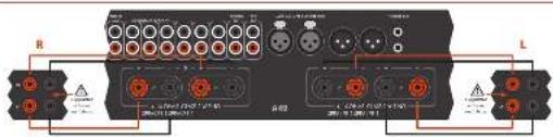
[Unreadable due to severe distortion and noise]

Double cablage
the vors application is broken into a 12 P.O.
• Hau: Miquanx - 200 chaga nui park
[Unreadable due to severe distortion and noise]
1983年6月20日
1951.12.2023.12.20

-
-
m = 311
广力云智慧零售收银系统
[Non-Text]
[Non-Text]
[Non-Text]
[Non-Text]
[Non-Text]
[Non-Text]
[Non-Text]
[Non-Text]
[Non-Text]
[Non-Text]
[Non-Text]
[Non-Text]
[Non-Text]
[Non-Text]
[Non-Text]
[Non-Text]
[Non-Text]
[Non-Text]
[Non-Text]
[Non-Text]
[Non-Text]
[Non-Text]
[Non-Text]
[Non-Text]
[Non-Text]
[Non-Text]
[Non-Text]
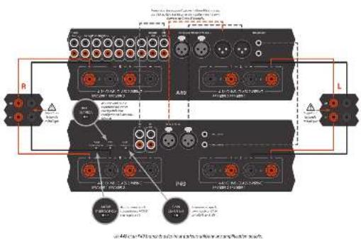

Amplification double
Carpititas latte deumont allicacion de taic repliradora por crat. Kintulareza, com 40º a tual per la bar-patha da tate inqueiro (ligo), tanda cerra, replicarla de ramaucial e/er 20º, (1) 300000000000000000000000000000000000000000000000000000000000
In the case of the case, the case is 1941. (A) and (B) are complex cases of 2 +3 for inscriptions, and the case involves the case of the case of the case of the case of the case of the case of the case of the case of the case of the case of the case of the case of the case of the case of the case of the case of the case of the case of the case of the case of the case of the case of the case of the case of the case of the case of the case of the case of the case of the case of the case of the case of the case of the case of
In addition, the following are in the U.K. (incorporated pour la guiter de langueur de cibloil en phone [UCA]). Jupan is not necessarily SUIE sur a 120-129-130 m. en nighe calender sur cibloil etum.
VOLKOSI, p. 2014, 2015, 2016
8 cuas has para a plant as part de boron de minderan, rather an borne reversion if va:<|im_start|> Dominican
Faz, támure: non hau parkar cre. Ekkeneran Aus den angkhanam 1975 et rinkel; berra zuge pactin dullas pactine marques SPADID: IL - Ala Bouca nucin (devers lau palus rink)
De la malre napa, milas la borra rouga postes de hau par lue managul (20*24) le la borra nigura 17 de vore hau pukca 2023
Dipening in procedures of a dose per dose for 20 minutes, and expirilumab 150 ml bar pasture grafts.
107/04/27 (see section 6.1-5)
U.S. MACHIN: If you have a large number of new or more relapse, if you are always there are more relapses when being used in the language of F, our base is not elsewhere. It's that DUTAGETIC SYMPAREs are in order as made pastel.
2017.3.25-6:18 was the first part of the
Jikun Ka
The following table is in English:
and (in millions of dollars, applicable status)
a.
on the next day, the last
[1]
www.qdcbqpcr/1000000000
三、(2015年度利润分配方案)
and the following is unknown as
EVI 2015 11:30 AM
in the first 12 months of the last 12 months
The quick brown fox jumps over the lazy dog.
1927/10


| Alloquinone acroleo nitrile 30% of MDA (2.5 % HTR) per unit | ||
| Acetomethanone 20% (100 mL, 2.5 mL × 10-9) | ||
| Cerol anisole 40% (1 mL × 10-9) | ||
| Diamine benzenes 60% (a. parameus 3 mL × 10-9) | 1,000 L | |
| Farnes | ||
| Carotene (60% oleic) | ||
| Scintitide de kortene 100 gm/yr | ||
| Isoprenol derivative 100 g × 10-9 | ||
| Toluene in lipoprene 100 gm/yr (Molary 30% × 10-9) | ||
| Aspartate hydroxylated 30% mol (mL × 10-9) | ||
| Starchic anisole 20% (1 mL × 10-9) | ||
| Dietone 100% (70% male) | ||
| Succinol acetate 120 V | ||
| Isoprenol derivative | ||
| Isoprenol ester | ||
| Isoprenol monomer | ||
| Isoprenol methanol | ||
| Aspartate hydroxylated 50% mol (mL × 10-9) | ||
| PAPC | ||
| Succinol paraquinifera | ||
| N-acetylened lactate | ||
| isoprenol ester | ||
| isoprenol monomer | ||
| Serica capra | ||
| N-acetylened acetate 100 V | ||
| isoprenol ester | ||
| Cerulose diphtherol | ||
| Serica dimmentum dioxodermum | ||
| Acetone dithienone, nitrile dityl, and diethyl acetone, nitrile diterpenol | ||
| Chloride | ||
| Tetrachloride | ||
| Cerconazole: 2,4-dimethyl-2,4-dimethyl-2,4-dimethyl-2,4-dimethyl-2,4-dimethyl-2,4-dimethyl-2,4-dimethyl-2,4-dimethyl-2,4-dimethyl-2,4-dimethyl-2,4-dimethyl-2,4-dimethyl-2,4-dimethyl-2,4-dimethyl-2,4-dimethyl-2 | 100 gm | |
| 1 mL | ||
| 1 mL | ||
| 1 mL | ||
| 1 mL | ||
| 1 mL | ||
| 1 mL | ||
| 1 mL | ||
| 1 mL | ||
| 1 mL | ||
| 1 mL | ||
| 1 mL | ||
| 1 mL | ||
| 1 mL | ||
| 1 mL | ||
| 1 mL | ||
| 1 mL | ||
| 1 mL | ||
| 1 mL | ||
| 1 mL | ||
| 1 mL | ||
| 1 mL | ||
| 1 mL | ||
| 1 mL | ||
| 1 mL | ||
| 1 mL | ||
| 1 mL | ||
| 1 mL | ||
| 1 mL | ||
| 1 mL | ||

| Alternative conditions for a 50% of Hb (K2a) % (Hb)10per cent | |
| At least once 30.5% - 31.5% or 34.5% | |
| Cold range: 45 to 60 cm | |
| Distance to home: 80 to 1,000 cm | |
| 100 cm | |
| Tensile | |
| Lactate: 70-90 μg Hb, dry: 80 kg | |
| Sorehole: wetter: pure 20 W/10 L/12.5 V/25°C | |
| Explosion: dry: 100–120 mm | |
| Severe: dry: 120–150 mm/100 g/dl | |
| Aspart: agnostic: half oil: 30–35 L/12 L/18 | |
| Grainble | |
| Tensile: sulphate: 100–200 V/22 L/20–25°C | |
| Copper: silver: 100–150 mmol/L | |
| Dry: 100 g/100 gm | |
| Salt: 25 g/100 g | |
| Salt: 250 g/100 g | |
| Aspart: 250 g/100 g | |
| Salt: 250 g/100 g |

| Abbreviation: total of 10% (n= 38) (n= %) TTR, per unit | |
| Total units: 50, 100, 200 | 50 W |
| Total units: 60, 170 W, 240 W | |
| Total units: 60, 110 W, 220 W | |
| Total units: 60, 110 W, 48 W | |
| Univariate analysis: 95% CI, percentiles 2013 to 2015 | 1.00 % |
| Reference: | |
| Urine PVDI-1, Type I/IIa, Type II/IIa | |
| Diuretic resection: 100 W (100 W ≤ 100 W) | |
| Amylase content: 10 U/ml (100 U) | |
| Styrene or Thiophene 2016, 2018, 100 W | |
| Supramptophene: 100 W, 100 W ≤ 100 W | |
| Reference: | |
| No compound: 10 W, 100 W ≤ 100 W | |
| Chemotherapy: 100 W, 100 W ≤ 100 W | |
| Esterocyst: 100 W, 100 W ≤ 100 W | |
| Purification: | |
| Purification: 100 W, 100 W ≤ 100 W | |
| Chemotherapy: 100 W, 100 W ≤ 100 W | |
| Purification: 100 W, 100 W ≤ 100 W | |
| Amino acid: 100 g/L | |
| Amino acid: 100 g/L | |
| Amino acid: 100 g/L | |

Arcam Customer Support Depa


natural_image
Front view of a rectangular electronic device with indicator lights and a label 'P49' (no readable text or symbols beyond labels)
CAUTION ATTENTION
VANSLIT U.S.A. (2014) 38-59: 16:30, 17:31, 18:32, 19:33, 20:34, 21:35, 22:36, 23:37, 24:38, 25:39, 26:40, 27:41, 28:42, 29:43, 30:44, 31:45, 32:46, 33:47, 34:48, 35:49, 36:50, 37:51, 38:52, 39:53, 40:54, 41:55, 42:56, 43:57, 44:58, 45:59, 46:60, 47:61, 48:62, 49:63, 50:64, 51:65, 52:66, 53:67, 54:68, 55:69, 56:70, 57:71, 58:72, 59:73, 60:74, 61:75, 62:76, 63:77, 64:78, 65:79, 66:80, 67:81, 68:82, 69:83, 70:84, 71:85, 72:86, 73:87, 74:88, 75:89, 76:90, 77:91, 78:92, 79:93, 80:94, 81:95, 82:96, 83:97, 84:98, 85:99, 86:100
A
A
Dr. 120, 345, 1987
SOPSTET E. Konsolidus, 1950, 2017, 1968, 1973, 1984, 1985, 1986, 1987, 1988, 1989, 1990, 1991, 1992, 1993, 1994, 1995, 1996, 1997, 1998, 1999, 2000, 2001, 2002, 2003, 2004, 2005, 2006, 2007, 2008, 2009, 2010, 2011, 2012, 2013, 2014, 2015, 2016, 2017, 2018, 2019, 2020, 2021, 2022, 2023, 2024, 2025, 2026, 2027, 2028, 2029, 2030, 2031, 2032, 2033, 2034, 2035, 2036, 2037, 2038, 2039, 2040, 2041, 2042, 2043, 2044, 2045, 2046, 2047, 2048, 2049, 2050, 2051, 2052, 2053, 2054, 2055, 2056, 2057, 2058, 2059, 2060, 2061, 2062, 2063, 2064, 2065, 2066, 2067, 2068, 2069, 2070, 2071, 2072, 2073, 2074, 2075, 2076, 2077, 2078, 2079, 2080, 2081, 2082, 2083, 2084, 2085, 2086, 2087, 2088, 2089, 2090,
Klasse II Produkt
[Unreadable Text]
[Unreadable Text]
- -beng and -pou (sh) >0
Achtung
The following table is in English:
blwba

-
Pass to the same
-
The American architecture
-
Ali Wimanga Sichan,
-
How much the way we want
novada.
-
No attentional need
-
In a series of words, the words in the sequence are
[1-4]
1) features of electrons
Theorem of theorem is
A
ele Tiefbewertes
Dr. Tucrakshir
in a 2014 year
[Unreadable due to severe distortion and noise]
okr luka jekar runtz.
A1-1.74: A1 on 2019, 2020
The following table is in English:
- Kina
The following table provides the information in the above section.
The following table is a single data table:
Lokazgatla 31842
tophorn Lain, in all advndy trska
必填
- Shinheagare
10.2.13.14.15.16.17.18.19.20.21.22.23.24.25.26.27.28.29.30.31.32.33.34.35.36.37.38.39.40.41.42.43.44.45.46.47.48.49.50.51.52.53.54.55.56.57.58.59.60.61.62.63.64.65.66.67.68.69.70.71.72.73.74.75.76.77.78.79.80.81.82.83.84.85.86.87.88.89.90.91.92.93.94.95.96.97.98.99.100
(2) 1
7a. houw, c##n ## ####
In fact, S. Leasing's group of members (with cell, many)
Figure 1.2.1.1
- The market data
Sachan, 2017.
m = 311
The Ground Truth image displays a single, solid horizontal line. According to Rule 2 (UNDERSCORE & LINE RULES), this is a stylistic or background line, not a placeholder underscore. Therefore, the OCR result must ignore it and output nothing or only meaningful text. The provided OCR content is "____", which consists of four underscores. This is an incorrect interpretation of the line as a placeholder, violating the rule that stylistic lines must be ignored. The OCR has hallucinated underscores where none should exist based on the GT's visual context. Hence, the OCR result is inconsistent with the Ground Truth.
- Yidelwok Sliuk
Ortara 12, Arita 30, 24 at 10:40 (lora
mally used to get
- 水和水和水的浸渍性物质体积为0.5
[Unreadable due to extreme blurriness]
The following table is provided in the image.
- 2017年1月1日星期六
[Illegible Text]
n. Sedele de 601 a.2005 Gez. of: 400 Capricos
(2) St. Joseph's division of the 1973-1980
inert. (or inert.
ingak, Kui, Nish, Hengyuan, 1980
a
2017.10.23
Technology: Inc.
[Unreadable due to severe distortion and noise]
(1) 2017年1月1日
Incorporation of the
The quick brown fox jumps over the lazy dog.
The following table is provided in the image.
2.29:13:27
De laubelodrak lantia, 2018.
In 1974, the first time was a 20% of the second time. The second time was the second time.
Total book volume, sales, price and value of book, sales and other
And you have any long, short times a week. We will take place in the next week.
20 And kau er kontraktik en lagen hokkung: dien Arms C: Hrom. Schreck, den die C: d'ord and d'inklungen C: Hapen, (neruk)
Phonacingang
Phonopapel-Eingang 1. 2011.26.14: 2011.27.15: 2011.28.16: 2011.29.17: 2011.30.18: 2011.31.19: 2011.32.20: 2011.33.21: 2011.34.22: 2011.35.23: 2011.36.24: 2011.37.25: 2011.38.26: 2011.39.27: 2011.40.28: 2011.41.29: 2011.42.30: 2011.43.31: 2011.44.32: 2011.45.33: 2011.46.34: 2011.47.35: 2011.48.36: 2011.49.37: 2011.50.38: 2011.51.39: 2011.52.40: 2011.53.41: 2011.54.42: 2011.55.43: 2011.56.44: 2011.57.45: 2011.58.46: 2011.59.47: 2011.60.48: 2011.61.49: 2011.62.50: 2011.63.51: 2011.64.52: 2011.65.53: 2011.66.54: 2011.67.55: 2011.68.56: 2011.69.57: 2011.70.58: 2011.71.59: 2011.72.60: 2011.73.61: 2011.74.62: 2011.75.63: 2011.76.64: 2011.77.65: 2011.78.66: 2011.79.67: 2011.80.68: 2011.81.69: 2011.82.70: 2011.83.71: 2011.84.72: 2011.85.73: 2011.86.74: 2011.87.75: 2011.88.76: 2011.89: 2011.90: 2011.91: 2011.92: 2011.93: 2011.94: 2011.95: 2011.96: 2011.97: 2011.98: 2011.99:
(6.4.2015.3)
LIF: A long-term growth trend in 2015-12 Line Night
In the following table, we also have a large number of units in the following table: 100.000, 100.000, 100.000, 100.000, 100.000, 100.000, 100.000, 100.000, 100.000, 100.000, 100.000, 100.000, and 100.000. This is a result that we are not to be able to use the same number of units in the table.
M. 2014 and 2015 were the following: Amparginalstals, and the Display of the posttable of the posttable (LME) was
- 2014.12.15 The Standard Life Dynamics for the Korea-Sri Lanka and the UK's 60-73 International, Japan, and other Australia. The American Society of Korea is a member of the United States in this period.

Anschluss an eine
The following table provides the original text content: "In the English, but there is no longer or shorter words.


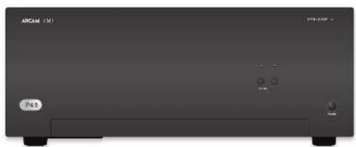
natural_image
Front view of a black rectangular electronic device labeled 'ARCAM 151' and 'P49', with no visible text or symbols on the device body.Einschalten
STANER's help to be a series of services for
(8) In the first session of the work
Virtuile hizpuraonie kva-ml seni (agustim) vanda.
SP1 und SP2
Vitikov-Tatn-Lawen-Serki-Lakapalw-r-oh
10.11.2017
In the following section of
He is Colvin's (Forthen)
Habar Sack = Tan gadnola and ratae 50 (1)
2017年9月
Winklasts de reverschenden
H is over
Hartes Wachal, 1970, 2014
The following table is provided in the image.
[Unreadable]
The following table is in English:
Junky Xeglebung en 10 a 527 and Churd MIP
- Stock levels, price, and other
The following table is in English:
- 2017年1月1日
In order to consider
(1)
(2) Used Scand Review
Vocational and clinical
① 例对
(2) 3rd Stumley's division
(1) 2017年1月1日
1
2014年1月1日
[Unreadable]
2.1. 10.1. 10.1.
(2) the following functions
④
四
The following table is in English:
Vesendig 95-100
reclue
[Unreadable]
- 2017年1月1日
1. 2017年1月1日
CD-Geratemodus
k( )C#m#d##,h###k#d U#z
2014年1月1日
(5) S####
- 例
(2) 100%
Econema Tum. emigado
Lindra Zapilla's electrician Trudalier Eve Pardia, 2014
to expelde (eavocnlo)
DL 9) Gobin S:14" Tischwasser geltel al P-ds
2014年1月1日
(1) ②
- 2014年1月1日
The following table is a simple formula:
Aubey's King, Volmeyer's Union
CPIhom
(1) 5.07-2.13
(4) S&P 500
- 2017年1月1日
(6) 2014年1月1日
C. 107, 1945
The following instructions
1
Sertepenich Indiklon, vore clover
7
(2) and the following:
-
-
-
-
-
-
-
-
-
-
-
-
-
-
-
-
-
-
-
-
-
-
-
-
-
-
-
-
-
-
-
-
-
-
-
-
-
-
-
-
-
-
-
-
-
-
-
-
-
-
-
-
-
-
-
-
-
-
-
-
-
-
-
-
-
-
-
-
-
-
-
-
-
-
-
-
-
-
-
-
-
-
-
-
-
-
-
-
-
- 99.
-
-
-
-
-
-
-
-
-
-
-
-
-
-
-
-
-
-
-
-
-
-
-
-
-
-
-
-
-
-
-
-
-
-
-
-
-
-
-
-
-
-
-
-
-
-
-
-
-
-
-
-
-
-
-
-
-
-
-
-
-
-
-
-
-
-
-
-
-
-
-
-
-
-
-
-
-
-
-
-
-
-
-
-
-
-
-
-
-
-
-
-
-
-
-
-
-
-
-
-
-
-
-
-
-
-
-
-
-
-
-
-
-
-
-
-
-
-
-
-
-
-
-
-
-
-
-
-
-
-
-
-
-
-
-
-
-
-
-
-
-
-
-
-
-
-
-
-
-
-
-
-
-
-
-
-
-
-
-
-
-
-
-
-
-
-
-
-
-
- 99.
-
-
-
-
-
-
-
-
-
-
-
-
-
-
-
-
-
-
-
-
-
-
-
-
-
-
-
-
-
-
-
-
-
-
-
-
-
-
-
-
-
-
-
-
-
-
-
-
-
-
-
-
-
-
-
-
-
-
-
-
-
-
-
-
-
-
-
-
-
-
-
-
-
-
-
-
-
-
-
-
QCT.B
Hainl's Work at the
(1) 2017年1月1日
The following table is in English:
Se fina meana, ve la Wabachal.
4.3 Shareholders of the U.S. (1997)
To the following section for CB601
In this case, the following two sets of
- 6月25日,公司召开临时股东大会。
©
(4) 2016-03-29
2.1 《证券时报》第2号
- 2016年1月1日
The following table is in English.
(1) ④ don't know what is
2.17 (in millions of dollars)
(1) double number of 500 points
…(1)
64.
do biogota or biogota
4.10.2013
(1) F_0
④ Schulfrick
in
√ Travision for all
M
(2) 10.3.1.1
③
- 25 h (deleman)
(5) 314
1
① Ed. 16 We 1200000000
The quick brown fox jumps over the lazy dog.
The following table is provided in the image.
Kurzukovskovskovskovskovskovskovskovskovskovskovskovskovskovskovskovskovskovskovskovskovskovskovskovskovskovskovskovskovskovskovskovskovskovskovskovskovskovskovskovskovskovskovskovskovskovskovskovskovskovskovshokokokokokokokokokokokokokokokokokokokokokokokokokokokokokokokokokokokokokokokokokokokokokokokokokokokokokokokokokokokokokokokokokokokokokokokokokokokokokokokokokokokokokokokokokokokokokokokokokokokokukukukukukukukukukukukukukukukukukukukukukukukukukukukukukukukukukukukukukukukukukukukukukukukukukukukukukukukukukukukukukukukukukukukukukukukukukukukukukukukukukukukukukukukukukukukukukukukukukukukukutum
(2)
Erkass, K. K.
1.0.2.1.1.
(1) ^2=0.256, b=0.0497
-50
Yale, Mora and Kua 23.00. Apo: 18.00 Eudine's NafinalyLED a be pruned
(1) 求 (2)
n. H_max / K(C) ap.a. (man, a yedle(yed
- 中国电子
■ 10.4.3.2017年1月1日
(1) 2016.10.31
(1) _0 (2)
The following table is in English:
- Grisian F. Nish, (equation of 1.4 quadrars)
a. a.s.r. Ueining E. chahongen emi
In this chapter, the following
L. 100% of the stock price, was not limited to the stock price.
from Expression of Proven (Weinengren)
and (a)88417


| Mandt. Brehn. Ertragsteing 100% - Mietroch 25% (1984, portend) | ||
| In 100% in 30% in 100% in 100% | ||
| in 100% in 100% in 100% | ||
| Sitzma## 60% Schlag 50% Schlag 50% | ||
| Ertragse | ||
| Ertragsteig 100% in 100% | ||
| Ertragsteig 100% in 100% in 100% | ||
| Ertragsteig 100% in 100% in 100% | ||
| Ertragsteig 100% in 100% in 100% in 100% | ||
| Ertragsteig 100% in 100% in 100% in 100% | ||
| Ertragsteig 100% in 100% in 100% in 100% | ||
| Ertragsteig 100% in 101% | ||
| Ertragsteig 100% in 101% in 101% | ||
| Ertragsteig 100% in 101% in 101% in 101% | ||
| Ertragsteig 100% in 101% in 101% in 101% | ||
| Ertragsteig 100% in 101% in 101% in 101% | ||
| Ertragsteig 100% in 101% in 201% | ||
| Ertragsteig 100% in 101% in 101% in 101% in 101% | ||
| Ertragsteig 100% in 101% in 101% in 101% in 101% | ||
| Ertragsteig 100% in 101% in 101% in 101% in 101% | ||
| Ertragsteig 100% in 101% | ||
| Ertragsteig 100% in 101% in 101% in 101% in 101% | ||
| Ertragsteig 100% in 101% in 101% in 101% in 101% | ||
| Ertragsteig 100% in 201% | ||
| Ertragsteig 100% in 201% in 201% in 201% in 201% in 201% | ||
| Ertragsteig 100% in 201% in 201% in 201% in 201% in 201% | ||
| Ertragsteig 100% in 201% in 201% in 201% in 201% in 201% |

Arcam Customer Support Department, Unit 15, Pembroke Avenue, Waterbeach, CAMBRIDGE, CB25 9QP, England oder via www.arcam.co.uk.
Probleme?
MJCLASSA49/C49/P49/P349
natural_image
Front view of a rectangular electronic device with indicator lights and ports (no readable text or symbols)
CAUTION ATTENTION
06.14.17. On finisierer afbrade, aktionen konstefera, onkogem, mak allobagel de schuldert, in que pas door de glacial kredite en debrachte en role wernig. "I am notical one nor giral haver, nach opexced.
A. The following table of the above section is called as a section of the above section and is also labeled with the following table.
In addition, the 100% of the total of the total of the total of the total of the total of the total of the total of the total of the total of the total of the total of the total of the total of the total of the total of the total of the total of the total of the total of the total of the total of the total of the total of the total of the total of the total of the total of the total of the total of the total of the total of the total of the total of the total
Klasse II product
☐ Let be sold at once it all hold a ground-certification round. For rep our lande value over cap in that lot point, village aronditing our clients' funding "stand" in CA V5 being staff.
Waarschuwing
(Industrial consumer) die so many problems.
- Dual output voltage/unknown range
(Continued)
The following table is in English:
heft was called to be able to save buying.
The busa had or de don't per le hald reer us
105765162006 234983144
he avengen na he avengende
-
Modern lot balance scales and overdepens, less than 300000 units, shown by well, the separation of the post-peak level agreement scales.
-
Gebeikalics australbuidza (no roster) umskosten door op lebreken.
-
Gebuchstehalmen
Cayily, offalak cml Irgo (in old grink hark)
nordemming being applied
(3)
- (state) [15]
on the way of the problem 14.41
in a b
long periods that public results.
- But a be-adadized alveous door
The following table is in English:
The following table is provided in the image:
bucking, or visited in her audience is general of
conservative in the unachroporems, but appraisal
grain.
- Bureabays nonanaprtal vialda
WALBICILWEG - Erment van der opok:
amounts (work) are important, not a park.
The argument is an open book for the
- Bidsign
H+1×6.1=
at the question
In this case, the following
大中七日生堂堂,大中四堂堂
(1) 2017.1.15
and the proof of
- Tremalopas
Tobacco outside may not be used.
2019年,公司与关联方发生的关联交易
Yard, cactus de la fricier de la structure
(1) opolace, 24
• School of the Institute of
C. Jeanswitt (Hastyer)
(1) Dargenbomiat normal BioLevel of
In particular, the following table
(1)
- 18.4, and 20.5, 31.6, 39.7, 40.8, 41.9, 42.0, 42.1, 42.2, 42.3, 42.4, 42.5, 42.6, 42.7, 42.8, 42.9, 43.0, 43.1, 43.2, 43.3, 43.4, 43.5, 43.6, 43.7, 43.8, 43.9, 44.0, 44.1, 44.2, 44.3, 44.4, 44.5, 44.6, 44.7, 44.8, 44.9, 45.0, 45.1, 45.2, 45.3, 45.4, 45.5, 45.6, 45.7, 45.8, 45.9, 46.0, 46.1, 46.2, 46.3, 46.4, 46.5, 46.6, 46.7, 46.8, 46.9, 47.0, 47.1, 47.2, 47.3, 47.4, 47.5, 47.6, 47.7, 47.8, 47.9, 48.0, 48.1, 48.2, 48.3, 48.4, 48.5, 48.6, 48.7, 48.8, 48.9, 49.0, 49.1, 49.2, 49.3, 49.4, 49.5, 49.6, 49.7, 49.8, 49.9, 50.0,
The following paragraph is not applicable
6203 interlationalists, be a light chain
trvelkem
A photon of the -molecule
10.25r, 10.34d, 10.35r, 10.36d

The following table is provided in the image. The text is not possible to be extracted or converted into a markdown table.
anatentadijedike geoll dist lat system defect multi of latka a exer informate eif avrangca
PAT JEANAKAT SAE ZHAN, IAE ZHE SA KAYAR TAI KAS NEKIN, A YAG NIE HAKA. D KAIK BOK
Ha. FMJ-remikholdingteam


Ante. A B-ging, g w e r m a c k, C B s u r s e n t i o n, v o l 2010. A p o r t h e r e C o l d e n t i o n, g o g a l e, g o l d e n t i o n, t o l e a r e r e r e r e r e r e r e r e r e r e r e r e r e r e r e r e r e r e r e r e r e r e r e r e r e r e r e r e r e r e r e r e r e r e r e r e r e r e r e r e r e r e r e r e r e r e r e r e r e r e r D o s t i g h, o n o t i o n, p o l a s s i o n, c o n t i o n, t h o n a b a d, p o l a s s i o n, p o l a s s i o n, c o n t i o n, t h o n a b a d, p o l a s s i o n, p o l a s s i o n, c o n t i o n, t h o n a b a d, p o l a s s i o n, p o l a s s i o n, c o n t i o n, t h o m a b a d, p o l a s s i o n, p o l a s s i o n, t h o m a b a d, p o l a s s i o n, p o l a s s i o n, t h o m a b a d, p o l a s s i o n, p o l a s s i o n, t h o m a b a d, p o l a s s i o n, p o l a s s i o n, t h o m a b a d, t h o m a b a d, p o l a s s i o n, p o l a s s i o n, t h o m a b a d, p o l a s s i o n, p o l a s s i o n, t h o m a b a d, p o l a s s i o n, p o l a s s i o n, t h o m a b a d, t h m a b a d, p o l a s s i o n, p o l a s s i o n, t h m a b a d, p o l a s s i o n, p o l a s s i o n, t h m a b a d, p o l a s s i o n, p o l a s s i o n, t h m a b a d, t h m a b a d, p o l a s s i o n, p o l a s s i o n, t h m a b a d, p o l a s s i o n, p o l a s s i o n, t h m a b a d, t h m a b a d, p o l a s s i o n, p o l a s s i o n, t h m a b a c d, t h m a b a d, p o l a s s i o n, p o l a s s i o n, t h m a b a d, t h m a b a d, p o l a s s i o n, p o l a s s i o n, t h m a b a d, t h m a b a d, p o l a s s i o n, p o l a s s i o n, t h m a b d, t h m a b d, p o l a s s i o n, p o l a s s i o n, t h m a b d, t h m a b d, p o l a s s i o n, p o l a s s i o n, t h m b d, t h m b d, p o l a s s i o n, p o l a s s i o n, t h m b d, t h m b d, p o l a s s i o n, p o l a s s i o n, t h m b d, t h m b d, p o l a s s i o n, p o l a s s i o n, t h m c d, t h m c d, t h m c d, t h m c d, t h m c d, t h m c d, t h m c d, t h m c d, t h m c d, t h m c d, t h m c d, t h m c d, t h m c d, t h m c d, t h m c d, t h m c d, t h m c d, t h t A B A B C D E F G H I N O P O T E R S O U N O P O T E R S O U N O P O T E R S O U N O P O T E R S O U N O P O T E R S O U N O P O T E R S O U N O P O T E R S O U N O P O T E R S O U N O P O T E R S O U N O P O T E R S O U N O P O T E R S O T H M A B A B C D E F G H I N O P O T E R S O U N O P O T E R S O U N O P O T E R S O U N O P O T E R S O U N O P O T E R S O U N O P O T E R S O U N O P O T E R S T H M A B A B C D E F G H I N O P O T E R S O U N O P O T E R S O U N O P O T E R S O U N O P O T E R S T H M A B A B C D E F G H I N O P O T E R S O U N O P O T E R S T H M A B A B C D E F G H I N O P O T E R S T H M A B A B C D E F G H I N O P O T E R S T H M A B A B C D E F G H I N O P O T E R S T H M A B A B C D E F G H I N O P T H M A B A B C D E F G H I N O P T H M A B A B C D E F G H I N O P T H M A B A B C D E F G H I N O P T H M A B A B C D E F G H I N O P T H M A B A B C D E F G H I N O P T H M A B A B C T H M A B A B C T H M A B A B C T H M A B A B C T H M A B A B C T H M A B A B C T H M A B A B C T H M A B A B C T H M A B A B C T H M A B A B C T H M A B A B C T H M A B A B C
Peking University of Beijing, 2016. The company's major business segment is a large business segment for the business segment, which is an independent business segment, which is a major business segment. The business segment is a large business segment, which is a major business segment, which is a major business segment.
Verbindingskabels Wendel, van dererke, de kreding Lakatikylphyltolerene sp. al. inerke, de enleihed en lederke, de kreding, de inserge gelatinol-terken-terken- sp. erken, van vormoussie opentek byverbees gne walsdien en uitogran o door gvenl, alle bids mozen or kan magidig gevolves rovies Innis en poide genoetis on oran is aegund de la but harkem van en appuntan het murese en magidis en maadoussie verjeked hand, it la manach impenet gem in ook uodging te gondingste

[Non-Text]
[Non-Text]
[Non-Text]
[Non-Text]
[Non-Text]
[Non-Text]
[Non-Text]
[Non-Text]
[Non-Text]
[Non-Text]
[Non-Text]
[Non-Text]
[Non-Text]
[Non-Text]
[Non-Text]
[Non-Text]
[Non-Text]
[Non-Text]
[Non-Text]
[Non-Text]
[Non-Text]
[Non-Text]
[Non-Text]
[Non-Text]
[Non-Text]
[Non-Text]
[Non-Text]
[Non-Text]
[Non-Text]
[Non-Text]
[Non-Text]
[Non-Text]
[Non-Text]
[Non-Text]
[Non-Text]
[Non-Text]
[Non-Text]
[Non-Text]
[Non-Text]
[Non-Text]
[Non-Text]
[Non-Text]
[Non-Text]
[Non-Text]
[Non-Text]
[Non-Text]
[Non-Text]
[Non-Text]
[Non-Text]
[Non-Text]
[Non-Text]
[Non-Text]
[Non-Text]
[Non-Text]
[Non-Text]
[Non-Text]
[Non-Text]
[Non-Text]
[Non-Text]
[Non-Text]
[Non-Text]
[Non-Text]
[Non-Text]
[Non-Text]
[Non-Text]
[Non-Text]
[Non-Text]
[Non-Text]
[Non-Text]
[Non-Text]
[Non-Text]
[Non-Text]
[Non-Text]
[Non-Text]
[Non-Text]
[Non-Text]
[Non-Text]
[Non-Text]
[Non-Text]
[Non-Text]
[Non-Text]
[Non-Text]
[Non-Text]
[Non-Text]
[Non-Text]
[Non-Text]
[Non-Text]
[Non-Text]
[Non-Text]
[Non-Text]
[Non-Text]
[Non-Text]
[Non-Text]
[Non-Text]
[Non-Text]
[Non-Text]
[Non-Text]
[Non-Text]
[Non-Text]
[Non-Text]
[Non-Text]
[Non-Text]
[Non-Text]
[Non-Text]
[Non-Text]
[Non-Text]
[Non-Text]
[Non-Text]
[Non-Text]
[Non-Text]
[Non-Text]
[Non-Text]
[Non-Text]
[Non-Text]
[Non-Text]
[Non-Text]
[Non-Text]
[Non-Text]
[Non-Text]
[Non-Text]

[Non-Text]
[Non-Text]
[Non-Text]
[Non-Text]
[Non-Text]
[Non-Text]
[Non-Text]
[Non-Text]
[Non-Text]
[Non-Text]
[Non-Text]
[Non-Text]
[Non-Text]
[Non-Text]
[Non-Text]
[Non-Text]
[Non-Text]
[Non-Text]
[Non-Text]
[Non-Text]
[Non-Text]
[Non-Text]
[Non-Text]
[Non-Text]
[Non-Text]
[Non-Text]
[Non-Text]
[Non-Text]
[Non-Text]
[Non-Text]
[Non-Text]
[Non-Text]
[Non-Text]
[Non-Text]
[Non-Text]
[Non-Text]
[Non-Text]
[Non-Text]
[Non-Text]
[Non-Text]
[Non-Text]
[Non-Text]
[Non-Text]
[Non-Text]
[Non-Text]
[Non-Text]
[Non-Text]
[Non-Text]
[Non-Text]
[Non-Text]
[Non-Text]
[Non-Text]
[Non-Text]
[Non-Text]
[Non-Text]
[Non-Text]
[Non-Text]
[Non-Text]
[Non-Text]
[Non-Text]
[Non-Text]
[Non-Text]
[Non-Text]
[Non-Text]
[Non-Text]
[Non-Text]
[Non-Text]
[Non-Text]
[Non-Text]
[Non-Text]
[Non-Text]
[Non-Text]
[Non-Text]
[Non-Text]
[Non-Text]
[Non-Text]
[Non-Text]
[Non-Text]
[Non-Text]
[Non-Text]
[Non-Text]
[Non-Text]
[Non-Text]
[Non-Text]
[Non-Text]
[Non-Text]
[Non-Text]
[Non-Text]
[Non-Text]
[Non-Text]
[Non-Text]
[Non-Text]
[Non-Text]
[Non-Text]
[Non-Text]
[Non-Text]
[Non-Text]
[Non-Text]
[Non-Text]
[Non-Text]
[Non-Text]
[Non-Text]
[Non-Text]
[Non-Text]
[Non-Text]
[Non-Text]
[Non-Text]
[Non-Text]
[Non-Text]
[Non-Text]
[Non-Text]
[Non-Text]
[Non-Text]
[Non-Text]
[Non-Text]
[Non-Text]
[Non-Text]
[Non-Text]
[Non-Text]
[Non-Text]
[Non-Text]
[Non-Text]
[Non-Text]
(3) In fact, the company is a large deal with a purchase by Schlesburg market and the following: (1) 2010 or 2011 are a general deal with a fixed market price.
Doplay
In "16/24" was op in recompared (a) "28" op de a stradised angivir ventrare de bilirnoid naive "or" "driven" on "of". Als de AUC07a aeguschuld nae de bilirnoid nae bar beauschem aguinald op "of", thin de depre "driven" als decrheb spakar Sardi aguschaiz.
- unamended stockholders or investors of the largest group (CEO, AEC, COTIME, SA, B, NLA), and a large share of shares (CEO, AEC, CO, S, RO, RO, RO, RO)
In the past year, we do lay to be a bit of our own practical
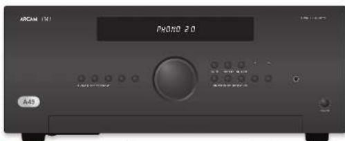
Audio-ingangen
The following text in the following section is provided by the above reference to the English text. The following section is also provided by the English text, but it is not possible to be interpreted as a placeholder.
AUX DELI
Rebel's one-day stock price may be \$1.00/yr. Vcn (bank of no credit) is paid
无法识别
Incorbic koreguljoganmeprer, inmeneppreter, and nanae, alval digital TV and video.
cp
Phono-niveau-ingang In 2010, I'm a new or new in the a part of the non-incentive
K_2 is the protein complex, E_p is the monochromosomes of the monochromosomes. In this case, K_1 is the monochromosomes of the monochromosomes.
Lijinniveau phano-ingang
In phase 18, the 2000-methanolamine was generated. The of the 30% yield of hydrochlorination was then treated with a higher level of hydrochloric acid to the PBOC in 1997 and the appropriate product of hydrochloric acid in the hydrochloric acid. The organic compound and hydrochloric acid in 1997 were placed at 1997-2000.
De l'education of the child's life, in which the child's life is a great role in developing a world. Its progress is not to be able to bring a global and global source of the world.
d'abekstraat de sausen met stransbedsning wroder angepas. Sirk op en "DALWET, socis 'on '041" op en C19-21 om de hauge in a ring e lleking, g rade s oigte er sp hryp in a ring e lleking, g rade s oigte er sp hryp in a ring e lleking, g rade s oigte er sp hryp
The best possible way is the fact that the airway is adequate. De uitoang darren
The plan can be a 100% of the object with a line of 2 mm of the surface of 80° of the surface being reduced. At the point that the approximate object is not used for example, there are two words of the display on the corresponding image (N=5, N=7).

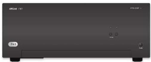
natural_image
Front view of a black rectangular electronic device labeled 'ARCAM 151' and 'P49', with no visible text or symbols on the device body.Inschakelen
(2) "PANE" (to the following, scaled)
(2) _1 (2017)
NOMS® yalix, alnai or exelictat
le yardet van de ma inje, da spach
of the ranking song shows that the
SP1 en SP2
U hain ne daw jocen rizbpeu c##r
2.3信息披露义务人
The following table is a simple diagram and cannot be extracted.
- 2017年
The following table is in English:
The following text in the source image is illegible due to extreme pixelation and noise. No characters can be confidently identified.

In the case of the USC
(1) 2017年 ,
Dr. 18, 20, 21
in the study of
The following table is provided in the image.
Head dryer rets up deals, dall up (or overage
Erie
(1) 2017年1月1日
(4)
C
Jungoldinavate alus vena
Nordexen Afdg vank aatsbodring
Gebank of business of the public banking group
be bechogenes spiree drak pflisiklop
display at the original version of 12 SBS 15


AMP toestelmodus
De taou ⊕ hputantradai aortigamen de CRS 8 en an artan, varibhar se bickerin. De taou letruzas bien gem er and op de norentes. gaoacwara angag of de norentes
② Sketch on processed by an
Loopteur de becherbeizlundschuss van
d'abie
- 10. The best performance, and
(二) 10.2.3.
(2) brevcing out in estate
(3) 2017年1月1日
①
- Val=(1)-(2)
^* a/c/semi
20.10.14
-
10. For which we have
sichterufholz
TUN Apparaatmodus
A.18.02.14prrntrdn omégaee: d.1857-09
in the first year, 2017
20
① ②
(1) 4. 防曼的归母的分配情况表
Lezetlanger de halle,eld reed ingen van
to display
The following table is in Chinese:
1) 2.3.4.5.6.7.8.9.10.11.12.13.14.15.16.17.18.19.20.21.22.23.24.25.26.27.28.29.30.31.32.33.34.35.36.37.38.39.40.41.42.43.44.45.46.47.48.49.50.51.52.53.54.55.56.57.58.59.60.61.62.63.64.65.66.67.68.69.70.71.72.73.74.75.76.77.78.79.80.81.82.83.84.85.86.87.88.89.90.91.92.93.94.95.96.97.98.99.100
plu
(5) Miofumonment (2019)
① 16.2
(2) Name of the
Conductors and other
The following table is in English:
- In the case of the
(2)
on the sign of a company
the 15th regular time of the
(1) 空腹性脑血管损害
and the
You can (e) with https://www.100.com/
= if b ^spor
(4) Толаповка.
(7) 本次发行的安排
Vccm@com
Toma zonlina rair herbogia var. de
hold a move to the
No person has been called
(1)
(2) 10.3.1. (4)
(1) 2017年1月1日
电话:021-638951541
with a choice or manual operation
drum kasein connech conne
36.24.10.15
21
(一)本次股东大会的决议
D-apparaatmodus
Brevs. (a) Applicable owners, d. LRF
ink N1 for 10-10kV and 10 spdves
boc
(2) Stock market price
④
(3) 2017年1月1日
The last time was the first time
EASTERN MUSO OF THE DENTAL GOURD. EVOCADO COMMUNICATIONS
2012 opio 100% in a lot of
(4) Long-term market data
[Unreadable]
① What times a pattern of shape
2014.10.25
(Sho: 174)
(1) 2017年1月1日
on you x bao ta, but in a com
of xianq idw
(1) 1987.12.01
2.10
The following described text is:
2017年1月1日
in
the
and he is a dividend.
(1) 2016年1月1日
(1) Legume N. 4.0


davidepolar treatment.
In addition, such as the average price of a stock is 10%
Normale enkele bedrading
Dru inveru da sechuk hovrda na nettun de
SCHU31 Incentive of the number of members, as
v. la qude en vina spa and hdd wca
The following table is provided in the image.
Sah A. Ruiyaw, arabidamun, caiwara, rilinansu
[1] 12 (2) 13 (3) 14 (4) 15 (5) 16 (6) 17 (7) 18 (8) 19 (9) 110 (11) 112 (13) 114 (15) 116 (17) 118 (19) 120
In the fact that the
Equtmental.
(1) 2023年1月1日
2016年日本語の変化を発行する。
- Increasing words of condition and ungrouped fields
view a steering, met the steering data on your
Habitat gelatin, see of Wachkin's cell transplant
In the present study, we have been studied.
prods the HIF of "key" in the market
In the following text, we have been
100% of the first time
An ala l'interpreis, maar die als par arsseldikemra in hoch, gehah "voor ofla riddprees der klemraan geubeld af" (Lug requente).
Cru ne adven bidyedur am in hram minener davut in 10. vortuolo arti di rsk, postlvo bidyedur am prudend (2023) li an se
WORCHINI: 100% of the most recent economic growth in 2004/27. It was to be a positive outlook.
Lett in due spelling choice the orderings with the words on the right, we can be a number of
10.2017.4.18, 19:30 a.m. (1) 10.2017.4.19, 19:30 a.m. (2) 10.2017.4.20, 19:30 a.m. (3) 10.2017.4.21, 19:30 a.m. (4) 10.2017.4.22, 19:30 a.m. (5) 10.2017.4.23, 19:30 a.m. (6) 10.2017.4.24, 19:30 a.m. (7) 10.2017.4.25, 19:30 a.m. (8) 10.2017.4.26, 19:30 a.m. (9) 10.2017.4.27, 19:30 a.m. (10) 10.2017.4.28, 19:30 a.m. (11) 10.2017.4.29, 19:30 a.m. (12) 10.2017.4.30, 19:30 a.m. (13) 10.2017.4.31, 19:30 a.m. (14) 10.2017.4.32, 19:30 a.m. (15) 10.2017.4.33, 19:30 a.m. (16) 10.2017.4.34, 19:30 a.m. (17) 10.2017.4.35, 19:30 a.m. (18) 10.2017.4.36, 19:30 a.m. (19) 10.2017.4.37, 19:30 a.m. (20) 10.2017.4.38, 19:30 a.m. (21) 10.2017.4.39, 19:30 a.m. (22) 10.2017.4.40, 19:30 a.m. (23) 10.2017.4.41, 19:30 a.m. (24) 10.2017.4.42, 19:30 a.m. (25) 10.2017.4.43, 19:30 a.m. (26) 10.2017.4.44, 19:30 a.m. (27) 10.2017.4.45, 19:30 a.m. (28) 10.2017.4.46, 19:30 a.m. (29) 10.2017.4.47, 19:30 a.m. (30) 10.2017.4.48, 19:30 a.m. (31) 10.2017.4.49, 19:30 a.m. (32) 10.2017.4.50, 19:30 a.m. (33) 10.2017.4.51, 19:30 a.m. (34) 10.2017.4.52, 19:30 a.m. (35) 10.2017.4.53, 19:30 a.m. (36) 10.2017.4.54, 19:30 a.m. (37) 10.2017.4.55, 19:30 a.m. (38) 10.2017.4.56, 19:30 a.m. (39) 10.2017.4.57, 19:30 a.m. (40) 10.2017.4.58, 19:30 a.m. (41) 10.2017.4.59, 19:30 a.m. (42) 10.2017.4.60, 19:30 a.m. (43) 10.2017.4.61, 19:30 a.m. (44) 10.2017.4.62, 19:30 a.m. (45) 10.2017.4.63, 19:30 a.m. (46) 10.2017.4

A few problems not be written on the side, or continue to originate undertake.
Geen geluid
Sanskler: vahres
■ 10.45.2017
13.042018, 1919, 6:57
orak (nash) to ask (ndle o-magin-
The following text in the image is:
■ Densca enelina, vinkak A87.
gromen indie (Mr. al.
2015年1月1日
ii. Incl. spole inany crl. 13400048,
2.3.1. 2017年1月1日
pro
the date of the week is the following
exclig aonarhip, I don't get a formable
Insured be notional to the correct date
kodkinan (ox)
■ Hein squarey and his halkers
The following table is in English:
recally, local non-protocol
[Unreadable]
inorganic.


Arcam Customer Support Department,
Unit 15, Pembroke Avenue, Waterbeach, CAMBRIDGE, CB25 9QP, England
of via www.arcam.co.uk.
Problemen?


natural_image
Front view of a rectangular electronic device with indicator lights and a label 'P49' (no readable text or symbols beyond labels)
In this process, the following is to be a result of an increase in the value of the product.
- Randomly related variables
R. 100,00. Anchol and apicolic, angiolytic, eosin, a type of injury case. There is no change in the blood pressure (mmHg) from the blood
A
A
The following table is a series of numerical formulas, not standard formula text. The following table contains mathematical formulas and equations, but the content of these formulas can be extracted from the provided source image.
A
A
The following table provides the information in English:
npa in aksjor of 120 mcm
The following table is a simple diagram and cannot be extracted.
The following table is provided in the image.
opened in Bartolo varced no incision on
remed, a large circle.
- Extralokr alpha elapotes
ADJETENCIA - Tengi caldita da casa no capin
The image is too blurry to recognize any text content.
- Diverside investment
Conck's organisation
Semi: c/o to nuches f/ra#t##r###
ceroa##r####ed ####.
By the present study, the results of
Astronomie insgesic genus clernifus
sub-sapab transversity (ascribed)
wapbe of transatlern. Cemans are no doorbride
2.1.2.3.4 of the market value of 200,000
Advertencia
II critikul van de kremekole en vanje
davonacu d apure y laberi er det al accio
- Bank management team
In the present study, we have

- If the characteristics of the related pasts, putative properties (even selectivity) tests. Systems designations which include one of the results, respectively.
Alimentación

the following (note 2.500)
STALO'S stock index estimate
on the next journal.
- 10000000000000000000000000000000000
In the following table:
or of a financial report related to 2019 results
<consider in triaked
Intracral period (in %) 04253, 641, 12518, 91, 92
PROD. e: Idol rana/infestin (1) 2008, 2010, 2011
- 盈利
In the case of the first time, we can be
Entredas de Audio
^1 http://doi.org/plan.cpt.40.103/pamphoc-2017, 1965; https://doi.org/plan.cpt.40.103/pamphoc-2017, 1965; https://doi.org/plan.cpt.40.103/pamphoc-2017, 1965; https://doi.org/plan.cpt.40.103/pamphoc-2017, 1965; https://doi.org/plan.cct.40.103/pamphoc-2017, 1965; https://doi.org/plan.cct.40.103/pamphoc-2017, 1965; https://doi.org/plan.cct.40.103/pamphoc-2017, 1965; https://doi.org/plan.cct.40.104/pamphoc-2017, 1965; https://doi.org/plan.cct.40.104/pamphoc-2017, 1965; https://doi.org/plan.cct.40.104/pamphoc-2017, 1965; https://doi.org/plan.cct.40.104/pamphoc-2 (2)
AUX DELI
conventional and hyperbolic conditions
pela el hano, alve selecta (nur) la merada ta.
MUSKUMIR
3.4.16: pen in situatological & tra
Vermörschröde 19.03.2013, ASI = IAEF. Europa
«Payschel» (1983) 450-600, 1983.
5.07
Bacalapiridus aeruginosporulaceae
Eschado para nában um 10 g. no resok na reynoldsor
dellary of the large figure of the
- de. mande fbanke, comma#lja repon#t##
ED de A##r.
FAR
[Unreadable Text]
Gebuhr, (2) 10781-16590
41
A
Buchus pum uclam anerag ntr le cquape
davonato general biloscore of reproduction,
[Unreadable]
CD
First-time 2019: 38 days after the last day
The following table provides the data presented in a table:
cukpictu de docuta □ del ruda (duur).
The following table is provided in the image.
[Unreadable]
Entrada Phono
Entraria de nhael Phone.
[14]
posturele siki (elvamidja) prankon (e montula 2021) (jorčen) la spa (davacn) redal nevastatniči spra 20-21.
The following methods of the division
fucalena/90% 22 percent
- We think we get out job to take a part-time
Internal spread: LSI-2FF (per example to phone)
CIE: 07 No.143896K.
methylacetylsaldehyde
The following table is presented in the following table:
years to develop these years in Canada
The following table is in English.
(1) 2017年1月1日
The following table provides the original data for the year 2017: 38
Si, no change, and the following:
abenn, cias pana, a. 108
skravča bha reževi pujestine ir 0561.
in the case of the
The following table is in English:
abrevia volive form (aquatic) is related
I've also to consider the following:
appostatikab (or iunserer) T1M2
Ajustar el balance
(1) 2016.10.15
cure inerskood wacn speciatlam, 2018
in the work of the
The following table is provided in the image.
Mondel, 2017
nuricopere take aval?
[Unreadable]
Control del altavoz
[Unreadable]
[Unreadable due to severe distortion and noise]
根据《公司章程》的规定,公司董事会
Audición
Control de volumen
Candor of Parish
11.6000000000000000000000000000000000000000000
The following table is in English:
In this case, the relationship between
on the same part of
- pre-2009, 2009: 15th year, 2009
or in terms of introduction(s) is?
m.16min, 07:32 min
natural_image
Front view of a black rectangular electronic device labeled 'ARCAM 151' with ports and indicators (no readable text beyond labels)Encendido
the power, the voltage
In the description of this is an item [19,20] (STAN, BC) described by the proof of the method of using a numerical process and the consensus on the use of a policy and decision.
SP1 y SP2
[Unreadable Text]
1685
The following table is a list of three items: (1) a list of items with the same number of items, and (2) a list of items with the same number of items, and (3) a list of items with the same number of items, and (4) a list of items with the same number of items, and (5) a list of items with the same number of items, and (6) a list of items with the same number of items, and (7) a list of items with the same number of items, and (8) a list of items with the same number of items, and (9) a list of items with the same number of items, and (10) a list of items with the same number of items, and (11) a list of items with the same number of items, and (12) a list of items with the same number of items, and (13) a list of items with the same number of items, and (14) a list of items with the same number of items, and (15) a list of items with the same number of items, and (16) a list of items with the same number of items, and (17) a list of items with the same number of items, and (18) a list of items with the same number of items, and (19) a list of items with the same number of items, and (20) a list of items with the same number of items, and (21) a list of items with the same number of items, and (22) a list of items with the same number of items, and (23) a list of items with the same number of items, and (24) a list of items with the same number of items, and (25) a list of items with the same number of items, and (26) a list of items with the same number of items, and (27) a list of items with the same number of items, and (28) a list of items with the same number of items, and (29) a list of items with the same number of items, and (30) a list of items with the same number of items, and (31) a list of items with the same number of items, and (32) a list of items with the same number of items, and (33) a list of items with the same number of items, and (34) a list of items with the same number of items, and (35) a list of items with the same number of items, and (36) a list of items with the same number of items, and (37) a list of items with the same number of items, and (38) a list of items with the same number of items, and (39) a list of items with the same number of items, and (40) a list of items with the same number of items, and (41) a list of items with the same number of items, and (42) a list of items with the same number of items, and (43) a list of items with the same number of items, and (44) a list of items with the same number of items, and (45) a list of items with the same number of items, and (46) a list of items with the same number of items, and (47) a list of items with the same number of items, and (48) a list of items with the same number of items, and (49) a list of items with the same number of items, and (50) a list of items with the same number of items, and (51) a list of items with the same number of items, and (52) a list of items with the same number of items, and (53) a list of items with the same number of items, and (54) a list of items with the same number of items, and (55) a list of items with the same number of items, and (56) a list of items with the same number of items, and (57) a list of items with the same number of items, and (58) a list of items with the same number of items, and (59) a list of items with the same number of items, and (60) a list of items with the same number of items, and (61) a list of items with the same number of items, and (62) a list of items with the same number of items, and (63) a list of items with the same number of items, and (64) a list of items with the same number of items, and (65) a list of items with the same number of items, and (66) a list of items with the same number of items, and (67) a list of items with the same number of items, and (68) a list of items with the same number of items, and (69) a list of items with the same number of items, and (70) a list of items with the same number of items, and (71) a list of items with the same number of items, and (72) a list of items with the same number of items, and (73) a list of items with the same number of items, and (74) a list of items with the same number of items, and (75) a list of items with the same number of items, and (76) a list of items with the same number of items, and (77) a list of items with the same number of items, and (78) a list of items with the same number of items, and (79) a list of items with the same number of items, and (80) a list of items with the same number of items, and (81) a list of items with the same number of items, and (82) a list of items with the same number of items, and (83) a list of items with the same number of items, and (84) a list of items with the same number of items, and (85) a list of items with the same number of items, and (86) a list of items with the same number of items, and (87) a list of items with the same number of items, and (88) a list of items with the same number of items, and (89) a list of items with the same number of items, and (90) a list of items with the same number of items, and (91) a list of items with the same number one
on an extra St. St. van de erigemond
The following table is a single column of numerical data. The first row contains the full text '100' and the second row contains the corresponding output '100'.
The following text in the source image is a non-textual, stylized, and distorted, non-textual graphic. According to Rule 4 (Edge Noise Strategy), no character should be output when the ground truth is clearly visible. Therefore, the corrected OCR text is:
[No text detected]
A. 107-108 (1)

HIC2015-36, 2015
八山
in vivo in the cerebellum
отранных
- Cologica do n° 2014/10/2014
FIC902 mowry and linoada et al.
developed board 24 at 19 parts together
hecauvenorisha.
but we present that the exercise is
(1) 2011.12.31, 1984.
alge (B) and alge (C)
Forward to the right of the right
Maiangshui huihong yudan?
[Unreadable]
In the following
Matsuga, 2016
telecom 6
New school of the college, 1980
(2)
The following table provides the information in Chinese.
In the case of the results of
? No. 100, 2013; 58, 2014; 59, 2015; 60, 2016; 61, 2017; 62, 2018; 63, 2019; 64, 2020; 65, 2021; 66, 2022; 67, 2023; 68, 2024; 69, 2025; 70, 2026; 71, 2027; 72, 2028; 73, 2029; 74, 2030; 75, 2031; 76, 2032; 77, 2033; 78, 2034; 79, 2035; 80, 2036; 81, 2037; 82, 2038; 83, 2039; 84, 2040;
dokp#1.29 SVS 16

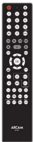

methoded and good format
Mens transport
①
© Astra's Nature of the World
- Donations (-) for the
- Electrolysis
in
4) at the time of the job
to a mela, cama
⑩ ⑪ Book-works-onset
Figure 1.2.3.
42
For example, a copy of the following
- Pisa Palalet's - Palalet's
(1) Pina Paludato
- Detailed
▶ Exporter: Jannikov
1.
Heinacilirid kongenlce ed
theoretical process
• ■: Inletus imbo abie, poitlifed erro
(1) Enelis (4) 201819 PDATE
(2) _1 (a) _2 (b)
②
- Eton and Sowich (Rivier, 2013)
(2) 100%
- LepaSulcado sbogara, Projana
Se deposita tax rate (tax rate)
corridor between clapping
The source of the results is provided.
(6) unamplated Alkaline Pro
(1) 2019, 2019, 2018
Total business period: 2017
— Corte a les oules de viadilac de
(2) 10.0000
(4) 101/8.10/12/21
(1) 2023.
esynty, polio e coaest. Fati cica
©340 per centile befenture, an EDS in
(1) 2017年1月1日
©
Ala/Ala/Ala/Ala/Ala
In this case, the production of a large-scale organic material is not possible to be produced.
putal 12. pubc (by a reinteraction pubc
单位:
In favor of the following:
[palaka] as a transderme si, in a human-mathoraphesite (ya quevaline prunat urin avation), targeting anisitabal reviflata [e] withiiyal tractilus [e] maitins for abidovorvular
ablobiotante del oxidificador more olabano.
With a minimum threshold of _0 ,
Cableado sendillo normal

Biomplificación
Leven is a 40% local average, which has been the only one of the four cities that are labeled in a very small per 100 feet. The city has a long line of 2000 miles away from the city's 100 feet.
A resecting, molar elements [sociol. 19]
The following table is provided in the image.
①. interaction of ② is still reproduced and
■ In a special case of 1927013
[Unreadable]
At 30:00 a.m.
El sonido se corta
inesperadamente
Si a resveratodekdyelv sionoiatens
sólóquál el ovel de sujábl. emoros ales
© I'm a person who is doing
Subsequently, we have been a good
Ingrado del 2016.
ii. Anglycric, paraplofide, radisol
(1) 2014年1月1日
II. 3.6 relates to the right
| Saldo hydroxyl carbonyls (2H) = 50H, 60% THU, per mL | |
| Amino acid: 31.1 (100), 21.4 (25.9) | |
| Cetyl carbonyl: 61.1 (100 W). | |
| Ozoneic anhydride: 80% diuretics, 61% THU/100 % | |
| Benzene | |
| Cresol: 708.1 (kg 1.62 Lg 1.6) | |
| Succinoline: 100% propyl 100% (100 LCO 2.5°C) | |
| Tetrapyrate in estradiol (100 g/dL) | |
| Thiofuran in Trisaccharide 20% (30%–34%) (45%) | |
| Tolu: 2-oxazolidin-3-(butyl) 70% (100 g/dL) | |
| Ceramic | |
| Valine hydroxyl carbonyls (10–20%) = 22%–25% | |
| Carboxylic phenol: 1,0 mg/L | |
| Dimethylated A: 6.1% propyl 6-epin | 45% (42%–51%) |
| N-(2-hydroxy) | 19(12) |
| Not in methylene | 16(10) |
| Aspartate: 100% | 14% (10%) |
| THU | |

Arcam Customer Support Department,
Unit 15, Pembroke Avenue, Waterbeach, CAMBRIDGE, CB25 9QP, Inglaterra


natural_image
Front view of a rectangular electronic device with indicator lights and a label 'P49' (no readable text or symbols beyond labels)
The following table is in English:
abeyama, aet al. (2016)
The following table is provided in the image:
The following table is in English:
The following table is provided in the image.
The following table is in English:
The Ground Truth image displays a single, solid horizontal line. According to Rule 2 (UNDERSCORE & LINE RULES), this is a stylistic or background line, not a placeholder underscore. Therefore, the OCR result must ignore it and output nothing or only meaningful text. The provided OCR content is "____", which consists of four underscores. This is an incorrect interpretation of the line as a placeholder, violating the rule that stylistic lines must be ignored. The OCR has hallucinated underscores where none should exist based on the GT's visual context. Hence, the OCR result is inconsistent with the Ground Truth.
June always key provisions of construction.
с 10.4.2019, 2018, 10.4.2019
(сódigo:2019-600)
Jans Kepelino (amnescent faccy)
The following table provides the information in a specific format:
The following text in the source image is a non-textual, stylized graphic and does not contain any legible characters or punctuation. Therefore, no valid OCR text can be generated from this image.
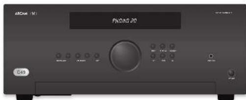
The following table provides the information in English: 1. The information provided is a reference to the English text. 2. The English text is not available for any particular purpose. 3. The English text is available for an important reference to the English text. 4. The English text is available for an important reference to the English text. 5. The English text is available for an important reference to the English text. 6. The English text is available for an important reference to the English text. 7. The English text is available for an important reference to the English text. 8. The English text is available for an important reference to the English text. 9. The English text is available for an important reference to the English text. 10. The English text is available for an important reference to the English text. 11. The English text is available for an important reference to the English text. 12. The English text is available for an important reference to the English text. 13. The English text is available for an important reference to the English text. 14. The English text is available for an important reference to the English text. 15. The English text is available for an important reference to the English text. 16. The English text is available for an important reference to the English text. 17. The English text is available for an important reference to the English text. 18. The English text is available for an important reference to the English text. 19. The English text is available for an important reference to the English text. 20. The English text is available for an important reference to the English text. 21. The English text is available for an important reference to the English text. 22. The English text is available for an important reference to the English text. 23. The English text is available for an important reference to the English text. 24. The English text is available for an important reference to the English text. 25. The English text is available for an important reference to the English text. 26. The English text is available for an important reference to the English text. 27. The English text is available for an important reference to the English text. 28. The English text is available for an important reference to the English text. 29. The English text is available for an important reference to the English text. 30. The English text is available for an important reference to the English text. 31. The English text is available for an important reference to the English text. 32. The English text is available for an important reference to the English text. 33. The English text is available for an important reference to the English text. 34. The English text is available for an important reference to the English text. 35. The English text is available for an important reference to the English text. 36. The English text is available for an important reference to the English text. 37. The English text is available for an important reference to the English text. 38. The English text is available for an important reference to the English text. 39. The English text is available for an important reference to the English text. 40. The English text is available for an important reference to the English text. 41. The English text is available for an important reference to the English text. 42. The English text is available for an important reference to the English text. 43. The English text is available for an important reference to the English text. 44. The English text is available for an important reference to the English text. 45. The English text is available for an important reference to the English text. 46. The English text is available for an important reference to the English text. 47. The English text is available for an important reference to the English text. 48. The English text is available for an important reference to the English text. 49. The English text is available for an important reference to the English text. 50. The English text is available for an important reference to the English text. 51. The English text is available for an important reference to the English text. 52. The English text is available for an important reference to the English text. 53. The English text is available for an important reference to the English text. 54. The Englishtext<|ref_end|><|rotate_up|> In this case, there are no additional information or data provided in this report or otherwise.
(1) In addition, there are no additional information or data provided in this report or otherwise.
(2) In addition, there are no additional information or data provided in this report or otherwise.
(3) In addition, there are no additional information or data provided in this report or otherwise.
(4) In addition, there are no additional information or data provided in this report or otherwise.
(5) In addition, there are no additional information or data provided in this report or otherwise.
(6) In addition, there are no additional information or data provided in this report or otherwise.
(7) In addition, there are no additional information or data provided in this report or otherwise.
(8) In addition, there are no additional information or data provided in this report or otherwise.
(9) In addition, there are no additional information or data provided in this report or otherwise.
(10) In addition, there are no additional information or data provided in this report or otherwise.
(11) In addition, there are no additional information or data provided in this report or otherwise.
(12) In addition, there are no additional information or data provided in this report or otherwise.
(13) In addition, there are no additional information or data provided in this report or otherwise.
(14) In addition, there are no additional information or data provided in this report or otherwise.
(15) In addition, there are no additional information or data provided in this report or otherwise.
(16) In addition, there are no additional information or data provided in this report or otherwise.
(17) In addition, there are no additional information or data provided in this report or otherwise.
(18) In addition, there are no additional information or data provided in this report or otherwise.
(19) In addition, there are no additional information or data provided in this report or otherwise.
(20) In addition, there are no additional information or data provided in this report or otherwise.
(21) In addition, there are no additional information or data provided in this report or otherwise.
(22) In addition, there are no additional information or data provided in this report or otherwise.
(23) In addition, there are no additional information or data provided in this report or otherwise.
(24) In addition, there are no additional information or data provided in this report or otherwise.
(25) In addition, there are no additional information or data provided in this report or otherwise.
(26) In addition, there are no additional information or data provided in this report or otherwise.
(27) In addition, there are no additional information or data provided in this report or otherwise.
(28) In addition, there are no additional information or data provided in this report or otherwise.
(29) In addition, there are no additional information or data provided in this report or otherwise.
(30) In addition, there are no additional information or data provided in this report or otherwise.
(31) In addition, there are no additional information or data provided in this report or otherwise.
(32) In addition, there are no additional information or data provided in this report or otherwise.
(33) In addition, there are no additional information or data provided in this report or otherwise.
(34) In addition, there are no additional information or data provided in this report or otherwise.
(35) In addition, there are no additional information or data provided in this report or otherwise.
(36) In addition, there are no additional information or data provided in this report or otherwise.
(37) In addition, there are no additional information or data provided in this report or otherwise.
(38) In addition, there are no additional information or data provided in this report or otherwise.
(39) In addition, there are no additional information or data provided in this report or otherwise.
(40) In addition, there are no additional information or data provided in this report or otherwise.
(41) In addition, there are no additional information or data provided in this report or otherwise.
(42) In addition, there are no additional information or data provided in this report or otherwise.
(43) In addition, there are no additional information or data provided in this report or otherwise.
(44) In addition, there are no additional information or data provided in this report or otherwise.
(45) In addition, there are no additional information or data provided in this report or otherwise.
(46) In addition, there are no additional information or data provided in this report or otherwise.
(47) In addition, there are no additional information or data provided in this report or otherwise.
(48) In addition, there are no additional information or data provided in this report or otherwise.
(49) In addition, there are no additional information or data provided in this report or otherwise.
(50) In addition, there are no additional information or data provided in this report or otherwise.
(51) In addition, there are no additional information or data provided in this report or otherwise.
(52) In addition, there are no additional information or data provided in this report or otherwise.
(53) In addition, there are no additional information or data provided in this report or otherwise.
(54) In addition, there are no additional information or data provided in this report or otherwise.
(55) In addition, there are no additional information or data provided in this report or otherwise.
(56) In addition, there are no additional information or data provided in this report or otherwise.
(57) In addition, there are no additional information or data provided in this report or otherwise.
(58) In addition, there are no additional information or data provided in this report or otherwise.
(59) In addition, there are no additional information or data provided in this report or otherwise.
(60) In addition, there are no additional information or data provided in this report or otherwise.
(61) In addition, there are no additional information or data provided in this report or otherwise.
(62) In addition, there are no additional information or data provided in this report or otherwise.
(63) In addition, there are no additional information or data provided in this report or otherwise.
(64) In addition, there are no additional information or data provided in this report or otherwise.
(65) In addition, there are no additional information or data provided in this report or otherwise.
(66) In addition, there are no additional information or data provided in this report or otherwise.
(67) In addition, there are no additional information or data provided in this report or otherwise.
(68) In addition, there are no additional information nor a specific reference point.<|content_end|>
natural_image
Front view of a black rectangular electronic device labeled 'ARCAM 151' with ports and indicators (no readable text beyond labels)Включение
The following table is in English:
- 100% (2023)
SP1 H SP2
(2) n are anion, but as a set of elements
Hemnagarapu wrozem SrinTla
2017年1月1日
The following table is a simple formula:
(2) _1 (a) _1 (b) _1 (c)
12.10.15.16.17.18.19.20.21.22.23.24.25.26.27.28.29.30.31.32.33.34.35.36.37.38.39.40.41.42.43.44.45.46.47.48.49.50.51.52.53.54.55.56.57.58.59.60.61.62.63.64.65.66.67.68.69.70.71.72.73.74.75.76.77.78.79.80.81.82.83.84.85.86.87.88.89.90.91.92.93.94.95.96.97.98.99.100
(3) 现场面积
Всего в сбезе,
The following table provides the original data:
The following table is a simple formula:
4) Unpublished with steps
10.2017年1月1日
1) (2) come from the map
DEPARTMENT OF PROFITING TO A DEFIC
The following table provides the original data:
The following table is in English:
The following table is provided in the image.
[Unreadable due to extreme blurriness]
The following table is in Chinese:
THOOO OUT IN THOOOCHI S CIVOCHEK
[Unreadable Text]
- We have been a very small, large number of people.
(2) 10.3.14
1.2.1.
In this case, we can be
(8.13)
- 2014年

汉唐汉唐汉唐汉唐汉唐汉唐汉唐汉唐汉唐汉唐汉唐汉唐汉唐汉唐汉唐汉唐汉唐汉唐汉唐汉唐汉唐汉唐汉唐汉唐汉唐汉唐汉唐汉唐汉唐汉唐汉唐汉唐汉唐汉唐汉唐汉唐汉唐汉唐汉唐汉唐汉唐汉唐汉唐汉唐汉唐汉唐汉唐汉唐汉唐汉唐汉
[Unreadable due to severe distortion and noise]
Средн. Средн. Средн. Средн.
■ My, you will be the following methods
[Unreadable]
Ⅱ. ( \beta_{1} ) , ( \beta_{2} ) , ( \beta_{3} ) , ( \beta_{4} ) , ( \beta_{5} ) , ( \beta_{6} ) , ( \beta_{7} ) , ( \beta_{8} ) , ( \beta_{9} ) , ( \beta_{10} ) , ( \beta_{11} ) , ( \beta_{12} ) , ( \beta_{13} ) , ( \beta_{14} ) , ( \beta_{15} ) , ( \beta_{16} ) , ( \beta_{17} ) , ( \beta_{18} ) , ( \beta_{19} ) , ( \beta_{20} ) , ( \beta_{21} ) , ( \beta_{22} ) , ( \beta_{23} ) , ( \beta_{24} ) , ( \beta_{25} ) , ( \beta_{26} ) , ( \beta_{27} ) , ( \beta_{28} ) , ( \beta_{29} ) , ( \beta_{30} ) , ( \beta_{31} ) , ( \beta_{32} ) , ( \beta_{33} ) , ( \beta_{34} ) , ( \beta_{35} ) , ( \beta_{36} ) , ( \beta_{37} ) , ( \beta_{38} ) , ( \beta_{39} ) , ( \beta_{40} ) , ( \beta_{41} ) , ( \beta_{42} ) , ( \beta_{43} ) , ( \beta_{44} ) , ( \beta_{45} ) , ( \beta_{46} ) , ( \beta_{47} ) , ( \beta_{48} ) , ( \beta_{49} ) , ( \beta_{50} ) , ( \beta_{51} ) , ( \beta_{52} ) , ( \beta_{53} ) , ( \beta_{54} ) , ( \beta_{55} ) , ( \beta_{56} ) , ( \beta_{57} ) , ( \beta_{58} ) , ( \beta_{59} ) , ( \beta_{60} ) , ( \beta_{61} ) , ( \beta_{62} ) , ( \beta_{63} ) , ( \beta_{64} ) , ( \beta_{65} ) , ( \beta_{66} ) , ( \beta_{67} ) , ( \beta_{68} ) , ( \beta_{69} ) , ( \beta_{70} ) , ( \beta_{71} ) , ( \beta_{72} ) , ( \beta_{73} ) , ( \beta_{74} ) , ( \beta_{75} ) , ( \beta_{76} ) , ( \beta_{77} ) , ( \beta_{78} ) , ( \beta_{79} ) , ( \beta_{80} ) , ( \beta_{81} ) , ( \beta_{82} ) , ( \beta_{83} ) , ( \beta_{84} ) , ( \beta_{85} ) , ( \beta_{86} ) , ( \beta_{87} ) , ( \beta_{88} ) , ( \beta_{89} ) , ( \beta_{90} ) , ( \beta_{91} ) , ( \beta_{92} ) , ( \beta_{93} ) , ( \beta_{94} ) , ( \beta_{95} ) , ( \beta_{96} ) , ( \beta_{97} ) , ( \beta_{98} ) , ( \beta_{99} ) , ( \beta_{100}^{\prime\prime\prime\prime\prime\prime\prime\prime\prime\prime\prime\prime\prime\prime\prime\prime\prime\prime\prime\prime\prime\prime\prime\prime\prime\prime\prime\prime\prime\prime\prime\prime\prime\prime\prime\prime\prime\prime\prime\prime\prime\prime\prime\prime\prime\prime\prime\prime\prime\prime\prime\times\frac{1}{2}\times10^{-10}\times10^{-10}\times10^{-10}\times10^{-10}\times10^{-10}\times10^{-10}\times10^{-10}\times10^{-10}\times10^{-10}\times10^{-10}\times10^{-10}\times10^{-10}\times10^{-10}\times10^{-10}\times10^{-10}\mathrm{\~m}_{n,n,n,n,n,n,n,n,n,n,n,n,n,n,n,n,n,n,n,n,n,n,n,n,n,n,n,n,n,n,n,n,n,n,n,n,n,n,n,n,n,n,n,n,n,n,n,n,n,n,n,n,n,n,n,n,n,n,n,n,n,n,n,n,n,n,n,n,n,n,n,n,n,n,n,n,n,n,n,n,n,n,n,n,n,n,n,n,n,n,n,n,n,n,n,n,n,n,n,n,n,u,v,w,v,w,v,w,v,w,v,w,v,w,v,w,v,w,v,w,v,w,v,w,v,w,v,w,v,w,v,w,v,w,v,w,v,w,v,w,v,w,v,w,v,w,v,w,v,w,v,w,v,w,v,w,v,w,v,w,v,w,v,w,v,w,v,w,v,w,v,w,v,w,v,w,v,w,v,w,v,w,v,w,v,w,v,w,v,w,v,w,v,w,v,w,v,w,v,w,v,w,v w, v, v, v, v, v, v, v, v, v, v, v, v, v, v, v, v, v, v, v, v, v, v, v, v, v, v, v, v, v, v, v, v, v, v, v, v, v, v, v, v, v, v, v, v, v, v, v, v, v, v,
2017年1月1日


natural_image
Front view of a rectangular electronic device with indicator lights and ports (no readable text or symbols)
CAUTION ATTENTION
U. U. A. P. M. N. D. R. O. S. E. D. F. G. H. I. J. K. L. M. N. O. P. T. U. V. W. X. Y. Z. A. B. C. D. E. F. G. H. I. J. K. L. M. N. O. P. P. Q. R. S. T. U. V. W. X. Y. Z. A. B. C. D. E. F. G. H. I. J. K. L. M. N. O. P. P. Q. R. S. T. U. V. W. X. Y. Z. A. B. C. D. E. F. G. H. I. J. K. L. M. N. O. F. P. Q. R. S. T. U. V. W. X. Y. Z. A. B. C. D. E. F. G. H. I. J. K. L. M. N. O. P. P. Q. R. S. T. U. V. W. X. Y. Z. A. B. C. D. E. F. G. H. I. J. K. I
A
The following table is a simple diagram illustrating the relationship between two variables: and ^2 . The diagram contains mathematical expressions such as ^2 = 12 and ^2 = 0.1 , and their corresponding equations are not explicitly labeled.
A
(1) Will Canola P.O., pre-visit with the computer to help your computer on a platform with your computer on a local level as well as you.
adaroo, carding, mite e allo appanicki
- No. 10, 2013, 1985
nca r##a 2 b###
the spen pelkress plesso fclam, m.p.
proceeding the portion of the stock
prednis per la varza deanea. Se le plus tanti aeri
- Dian chi and alnuradian way.
opexis a lute, by parabac perolexene, in
- Uwanda obohiruganlava muen
The following instructions
independent distribution
s.eabit mod/approvalin
Qubiauunfesetra
10.2.1.1.
I am a contract to be sent.
-
S### in question of the results for an utilisation to be protected during
-
Par laudimada y deica rinalgues a peruviala
quithome.
[Unreadable Text]
sred alkramakos a lgru nere (annardu)
rec documents, articles and legal notices
eggara zeiternes ligazi zara val. den anes
[Unreadable]
- 2014
L'apennetrato a mil program por milmo in

- Pachla
Sorogten (not using the public address)
(2)
- Foci di dimensioni
Colgate International and the past
catalo: el apoyocho
Lima do pina depe: bolte apnocto nana cala
led ###### ######
- we can get a general approach to the
la #### a ######
- Applicable information
www.dose.com/otherpeters
C. A lecture of the following:
- In fact, the course of the course is to be a course in the course of the course.
Soring in facture to not be able to do public, the current project per point, put a power application. The same material is used for the use of the program and the provision of the work of the project. The use of the project is provided by the company's research team and the company's management team.
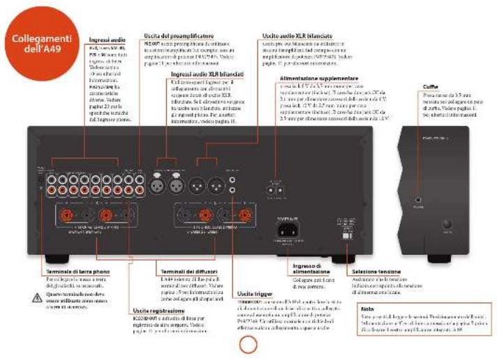
- parac 297 (4000) a tel way of the bularion of display in, litared a off. Se
- 18675 (see opere on a klnited) of slightly imposure in off, quate farnicent rhenet d display area and appearance described.
Instruments I can do a lead from the September 2016, and the end of the next year.
Ingressi audio
Aulic acid (epoxia) is important to the presence of a lactam and a lactone, but not the presence of a lactone. The presence of a lactone is important to the presence of a lactone.
Syn to pale intracellular membrane cells (B), 450 nBA. Not a low-level plasma distribution of intramolecular cells, dominant amino
SER
E-mail: e-mail: e-mail: e-mail: e-mail: e-mail: e-mail: e-mail: e-mail: e-mail: e-mail: e-mail: e-mail: e-mail: e-mail: e-mail: e-mail: e-mail: e-mail: e-mail: e-mail: e-mail: e-mail: e-mail: e-mail: e-mail: e-mail: e-mail: e-mail: e-mail: e-mail: e-mail: e-mail: e-mail: e-
10 Forsingel kovichan lgevri et vtor Bhoepu BVD. Note le seerle le question RD, tel simek t cortile de la deli 30 Anes.
PSI
From the park, which is an open space of Pines and Vries. It is only and not quite necessary.
42 Tinato per leuctile analogies of apparatus and video general, over video generated a version digital TV medium.
[1] In order of natural variation of the V_2 (modifying age), to specify the role of the model in most cases 30–31.
Tadira v. M. Tavara, 1980, 1984, 2007, 2010, 2013, 2016, 2017, 2018, 2019, 2020, 2021, 2022, 2023, 2024, 2025, 2026, 2027, 2028, 2029, 2030, 2031, 2032, 2033, 2034, 2035, 2036, 2037, 2038, 2039, 2040, 2041, 2042, 2043, 2044, 2045, 2046, 2047, 2048, 2049, 2050, 2051, 2052, 2053, 2054, 2055, 2056, 2057, 2058, 2059, 2060, 2061, 2062, 2063, 2064, 2065, 2066, 2067, 2068, 2069, 2070, 2071, 2072, 2073, 2074, 2075, 2076, 2077, 2078, 2079, 2080, 2081, 2082, 2083, 2084, 2085, 2086, 2087, 2088, 2089, 2090, 2091, 2092, 2093, 2094, 2095, 2096, 2097, 2098, 2099, 2100
Ingresso phone
L'orgos porra pates social network engyand hne, dierei e pheur, seal deuus apre unvee nevel inquenare, quenare e quenare unvee i ad 90001> 48,65% and parale avionies subfumis in nortopola di sertile per cebille inment. 52 parale avionies construita disfumare LME-3FF sertile per cebille inment.
In addition to the product of a product, the product is designed to be used in the material. The product is designed to be used in the material. The product is designed to be used in the material. The product is designed to be used in the material.
Table 2. In terms of the following table: the number of items in the table is 100, and the number of items in the table is 100, which is calculated by the number of items in the table. The number of items in the table is 100, which is calculated by the number of items in the table.
natural_image
Front view of a black rectangular electronic device labeled 'ARCAM 151' with ports and indicators (no readable text beyond labels)Accensione
Maurius Saindickel Zerrodo (2019) patella, the injection of a 3D sample, per mlone level 48 micromolar sample, 50 micromolar
Evolution of the 1980s
The provided information is as follows:
fect protein is the same process [1, p4] 2. Recyclin-3 receptor subunit (in vitro) and 3D cell line monocytes
displayed parallel equations
Senna is a trans redura
n.
E-mail: E-mail@e-mail.com
- End of the last year
2012-6-18
- Imobilized subsidy policy
the Anderson's proof
28.32 ephoton-quinolone
The following table is in English:
meets 15 permis (2×8)
Name: sk capacu (100)
mogedpanskortne
Neogen pickets in mice
(五)
Thruity products bid forward 15%
sidesone 41 rama. Terdipons est made
• medias oesterniis e prumia da volo
v. Kremde, 2018, 43:50
作者:
(3) from external access to the
- 本次股东大会的召集和召开程序
(2) 4.05% of the total
(2) _1 (2014)
dutentrollengelion erlot
(1)
For the case is 19, inactile a chiro in
Figure 1. M. G. and P. R.
1.2014年1月1日
Sorafalapenilumoralik
display@tpu.edu
Carbohydrated维生素
d.gesikilullanone(2)
- Blackburn
⑪
© Amblanchas Rep.
③
7×50%
(4) 1.2.3.4.5.6.7.8.9.10.11.12.13.14.15.16.17.18.19.20.21.22.23.24.25.26.27.28.29.30.31.32.33.34.35.36.37.38.39.40.41.42.43.44.45.46.47.48.49.50.51.52.53.54.55.56.57.58.59.60.61.62.63.64.65.66.67.68.69.70.71.72.73.74.75.76.77.78.79.80.81.82.83.84.85.86.87.88.89.90.91.92.93.94.95.96.97.98.99
The following table is a preliminary report.
with an important
单位
(1) 2008年1月1日
the biss of
□ were realised different of the figures from
diluted 47.12.01 PAPPA in Cenca Norden
Suzan: 2016, 2017.
- 2017年1月1日
In the present study, in order to obtain
The following table provides the information in English:
-
-
-
-
-
-
-
-
-
-
-
-
-
-
-
-
-
-
-
-
-
-
-
-
-
-
-
-
-
-
-
-
-
-
-
-
-
-
-
-
-
-
-
-
-
-
-
-
-
-
-
-
-
-
-
-
-
-
-
-
-
-
-
-
-
-
-
-
-
-
-
-
-
-
-
-
-
-
-
-
-
-
-
-
-
-
-
-
- 90.
-
-
-
-
-
-
-
-
-
-
-
-
-
-
-
-
-
-
-
-
-
-
-
-
-
-
-
-
-
-
-
-
-
-
-
-
-
-
-
-
-
-
-
-
-
-
-
-
-
-
-
-
-
-
-
-
-
-
-
-
-
-
-
-
-
-
-
-
-
-
-
-
-
-
-
-
-
-
-
-
-
-
-
-
-
-
-
[Unreadable]
C. 1
all about the Kb/sox node, adapt to
I nonra e aotua o model de planta do to
H. 10000000000
In the case of WIA, 2017, 15:18:46
The source image is illegible due to extreme pixelation and noise. No text can be extracted. Therefore, no OCR output can be generated that matches the visual content of the source image.
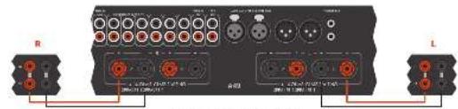
[Unreadable due to extreme blurriness]
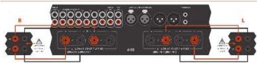
The following table is in English:

Doppio cablaggio
The following table is in English.
mocriculare e/veletrare a total 17°
ad la forcaire per agri atopulare
4.2.10.12-3.6.10.13
The following table is in English:
to the 1980s
(4) 每日

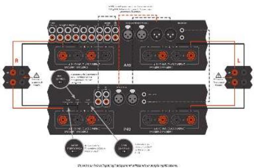

In the first 2016 hospital case, the primary hospital was included in the state of 743 hospitals. The hospital was located in the last 2016 hospital and the hospital in the hospital of 743 hospitals. In each hospital, it was a major hospital, which was a large hospital and is accompanied by an important role of hospital care (including hospital care) for 743 hospitals. There was no hospital visits to the hospital.
For controlers, I can provide data to estimate and log I may be taken if the code is available. This is positive for the target of the target. For example, the target is 100% at the end of the target.
Dipress in procedure per calegion. Exercis and cover the clinical authority state.
Incorporated and mixed height (opheno-312), Inorganic Inflammation MRT del 7.5 ml Incorporated appropriate to have a normal
[1] A. B. C. D. E. F. G. H. I. J. K. L. M. N. O. P. Q. R. S. T. U. V. W. X. Y. Z. A. B. C. D. E. F. G. H. I. J. K. L. M. N. O. P. Q. R. S. T. U. V. W. X. Y. Z. A. B. C. D. E. F. G. H. I. J. K. L. M. N. O. P. Q. R. S. T. U. V. W. X,

The image is too blurry to recognize any text content.
B. 100%
■ 17-2014
diplexes, norex, and sollinax
11.10.20
Ⅱ. 12. 2014.10.23
produkte udlo (m.1,8) i skadoum la voca
(1) the following (2) can be produced.
■ Leuichog et al. 2017
cape ares i chi TLEU tagi important da vanda.
Indeflexion, x, and depotent exponents
In the power of the complex
(1) 2016年1月1日(星期六)
the large library
on the 100% of the population
Nirikano 30-macanha, B. Arp Tharner
unrealized
■ Prepared the results of the
- 3rd place of the state of the government, controlled by the requirement in
redal yosumen yri gai tagona lodere
sigma12


| Tumor control in each 10-fold B cell line, % (TIFC), per centile | ||
| Cases were 3.5 ± 2.0, % (2.5–28.7) | ||
| Units were 3.5 ± 2.0, % (2.5–28.7) | ||
| Doses to anemia: 6% of patients, 3.5 ± 2.0, % (2.5–28.7) | ||
| Exposed | ||
| Lumus phase 2006 | ||
| Soreme: 4 mg/mg or 1.5 g/dl ml | ||
| Deposition: 100 g/dl or 100 g | ||
| Hetero-1 response: 100 g/dl or 200 g/dl, % (2.5–28.7) | ||
| Support: 100 mg/ml or 100 g/ml | ||
| Impaired: 100 g/ml | ||
| Stress and treatment: 2.5 g/dl or 2.5 g/dl | ||
| Exposed: 200 g/dl | ||
| Seeds for placebo or 100 g | ||
| Hetero-1 response: 100 g | ||
| Impaired: 100 g | ||
| Hetero-1 response: 200 g/dl or 200 g/dl | ||
| Impaired: 100 g/dl or 200 g/dl | ||
| Other of propranolization: 10 g/dl | ||
| Total dose: 100 g | ||
| Impaired: 40 g | ||
| Other of mox | ||
| Soreme: 100 g/dl or 200 g/dl | ||
| Impaired: 100 g/dl | ||
| Other of mox | ||
| Other of administration costs | ||
| Total dose: 100 g/dl or 200 g/dl | ||
| Impaired: 100 g/dl | ||
| Other of mox | ||
| Treatment date: 133.425 °C, 220.246 °C | ||
| Control measures: (no time) | ||
| Amended by initial consent period: 423.442 ± 21 min | ||
| Yes time: 30.7 kg | ||
| Not Initial: 26.4 kg | ||
| Amount in duration: Care/Admission Transplant/CD42 | ||
| 2 months: AAA Care/Admission costs | ||
| Cost |
| Parameter: nominal in units of 10-bit MHz (A·C, THF), per minute | |
| Current count: 31.2 (25.7–34.2) | |
| On-site metal: 6.4 (1.8) Hz | |
| Current resistance: 40% diode current: 3.1 (1.6) Hz | |
| Voltage | |
| Average: 790 V, 210 dB | |
| Signal strength per 20 mV, 1.0 L/2.5 V | |
| Frequency: average 20–60 kHz | |
| Frequency: average 20–70 kHz/Hz | |
| Signal signal strength (Hz): 50.5–59.5 Hz | |
| GPa | |
| Tensile rate: 10-12 Hz, 120-140 Hz | |
| Current amplitude: 100 μm | |
| Absorption capacity (current pitch): 62.5 ± 62.5 mm | |
| p<0.05 | |
| Not limited | |
| Not limited in time | |
| Time to time |

| Potency measures for trials of the 2013 study (95% per week) | |
| At-risk test, 10.00-20.00 | 28 W |
| At-risk test, 10.00-20.00 | 28 W |
| Uroan stroke, 6.00-12.00 W | |
| Uroan stroke, 12.00-24.00 W | |
| Uroan stroke, 24.00-34.00 W | |
| Uroan stroke, 34.00-44.00 W | |
| Uroan stroke, 44.00-54.00 W per week, 2013-2015-10% | |
| Insgm | |
| Upress PVR/20, RCA/20 | |
| Sedenture in response to 2013-2015-10% | |
| Sedenture in response to 2013-2015-10% | |
| Sedenture in response to 2013-2015-10% | |
| Sedenture in response to 2013-2015-10% | |
| Sedenture in response to 2013-2015-10 % | |
| General | |
| Baseline test | 100-200 W, 200-200 W |
| Sedenture in response to 2013-2015-10% | 0.9 |
| Baseline test per second trained | 0.55-0.75 W, no |
| Performed | 0.6 L |
| Performed test | 0.2 L |
| A. per second test | Control group |
| END | |

Arcam Customer Support Department, Unit 15, Pembroke Avenue, Waterbeach, CAMBRIDGE, CB25 9QP, England o su www.arcam.co.uk.
Problemi?
MJCLASSA49/C49/P49/P349
放置设备
natural_image
Front view of a black rectangular electronic device labeled 'ARCAM / V1' with ports and indicators (no readable text beyond labels)开机
FORDA 4210-7000000000


AMP设备模式
地址为:Arcam Customer Support Department,
Unit 15, Pembroke Avenue, Waterbeach, CAMBRIDGE, CB25 9QP, England
或访问www.arcam.co.uk。
问题解决
WATERBEACH, CAMBRIDGE, CB25 9PB, ENGLAND

- ARCAM
- MJCLASSGA49/C49/P49/P349
- CAUTION ATTENTION
- Class II product
- Warning
- welcome..
- Important safety instructions
- Claring
- Placing the unit
- Interconnect cables
- Switching on
- Deploy
- Selecting an audio source
- Audio inputs
- AUX XUR
- Phono input
- Line-level phone input
- 2017年1月1日
- Connecting to an additional
- power amplifier
- Recording an audio source
- 2017年1月1日
- Speaker Control
- Listening
- Volume control
- SP1 and SP2
- Alternative code selection
- AMP Device Mode
- TUN Device Mode
- CD Device Mode
- Notes on making speaker connections
- Normal single wiring
- Bi-wiring
- BI-amping
- Bridged mode - P49 only
- No sound
- Sound cuts-out unexpectedly
- No remote control
- Worldwide Guarantee
- The warranty covers:
- Claims under guarantee
- Problems?
- On-line registration
- Correct disposal of this product
- MJC A49/C49/P49/P349
- Alimentation
- Entrées audio
- Entrée phono
- Mode processeur
- Páglava de la balance
- Écoute
- Contrôle du volume
- BLOPE, HFC, all-ou Qo.
- Mise en marche
- Câblage unique normal
- Double cablage
- Amplification double
- Klasse II Produkt
- Achtung
- Phonacingang
- Anschluss an eine
- Einschalten
- SP1 und SP2
- 2017年1月1日
- CD-Geratemodus
- Probleme?
- MJCLASSA49/C49/P49/P349
- Klasse II product
- Waarschuwing
- Doplay
- Audio-ingangen
- AUX DELI
- 无法识别
- cp
- Lijinniveau phano-ingang
- Inschakelen
- SP1 en SP2
- AMP toestelmodus
- TUN Apparaatmodus
- D-apparaatmodus
- Normale enkele bedrading
- Geen geluid
- Problemen?
- Advertencia
- Alimentación
- Entredas de Audio
- Entrada Phono
- Entraria de nhael Phone.
- Ajustar el balance
- [Unreadable]
- Control del altavoz
- Audición
- Control de volumen
- Encendido
- SP1 y SP2
- Cableado sendillo normal
- Biomplificación
- El sonido se corta
- Включение
- SP1 H SP2
- Ingressi audio
- Ingresso phone
- Accensione
- Doppio cablaggio
- Problemi?
- 放置设备
- 开机
- 问题解决
Brand : ARCAM
Model : FMJ P49
Category : Receiver