PRSD410 - AV receiver PIONEER - Free user manual and instructions
Find the device manual for free PRSD410 PIONEER in PDF.
| Product type | Car audio amplifier |
| Brand | Pioneer |
| Model | PRSD410 |
| Maximum output power | 150 W × 4 (4 Ω) / 600 W × 2 (4 Ω) |
| Continuous output power | 75 W × 4 (14.4 V, 4 Ω, 20 Hz-20 kHz, 1% THD) / 300 W × 2 (14.4 V, 4 Ω, 1 kHz, 1% THD) |
| Load impedance | 4 Ω (2 to 8 Ω admissible, bridged: 4 to 8 Ω) |
| Frequency response | 10 Hz - 50 kHz (+0 dB, -3 dB) |
| Signal-to-noise ratio | 100 dB (IEC-A network) |
| Total harmonic distortion | 0.005% (10 W, 1 kHz) |
| Filters | Low-pass and high-pass, cutoff frequency 40 Hz - 500 Hz, slope -12 dB/octave |
| Gain control | RCA input: 400 mV to 6.5 V; Speaker input: 1.6 V to 26 V |
| Power supply | 14.4 V DC (10.8 to 15.1 V admissible) |
| Current consumption | 28 A (continuous, 4 Ω); average: 10 A (4 ch 4 Ω), 20 A (2 ch 4 Ω or 4 ch 2 Ω) |
| Fuse | 30 A × 2 |
| Dimensions (W × H × D) | 304 × 56 × 195 mm |
| Weight | 3.0 kg (without cables) |
| Grounding | Battery negative terminal |
| Protection | Protection circuit against overloads and short circuits |
| Inputs | RCA jacks and speaker input (harness supplied) |
| Speaker outputs | Screw terminals for 2/3/4-channel configurations, bridged possible |
| Installation | Self-tapping screw mounting on carpet or chassis |
| Care and cleaning | Avoid any contact with liquids; clean with a dry cloth |
| Safety | Disconnect the battery before installation; use only fuses of the same rating |
| Spare parts and repairability | 30 A fuse; battery connection harness RD-223 (sold separately); contact an authorized Pioneer center |
| General information | Manual available in multiple languages; product registration at pioneer.fr |
Frequently Asked Questions - PRSD410 PIONEER
User questions about PRSD410 PIONEER
0 question about this device. Answer the ones you know or ask your own.
Ask a new question about this device
Download the instructions for your AV receiver in PDF format for free! Find your manual PRSD410 - PIONEER and take your electronic device back in hand. On this page are published all the documents necessary for the use of your device. PRSD410 by PIONEER.
USER MANUAL PRSD410 PIONEER
BRIDGEABLE FOUR-CHANNEL POWER AMPLIFIER
AMPLIFICATEUR DE PUISSANCE PONTABLE A QUATRE VOIES
Owner's Manual
PRS-D410
Mode d'emploi
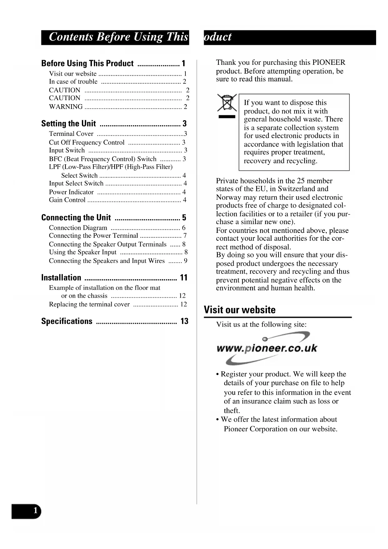
Contents Before Using This
Before Using This Product .... 1
Visit our website 1
In case of trouble 2
CAUTION 2
CAUTION 2
WARNING 2
Setting the Unit .... 3
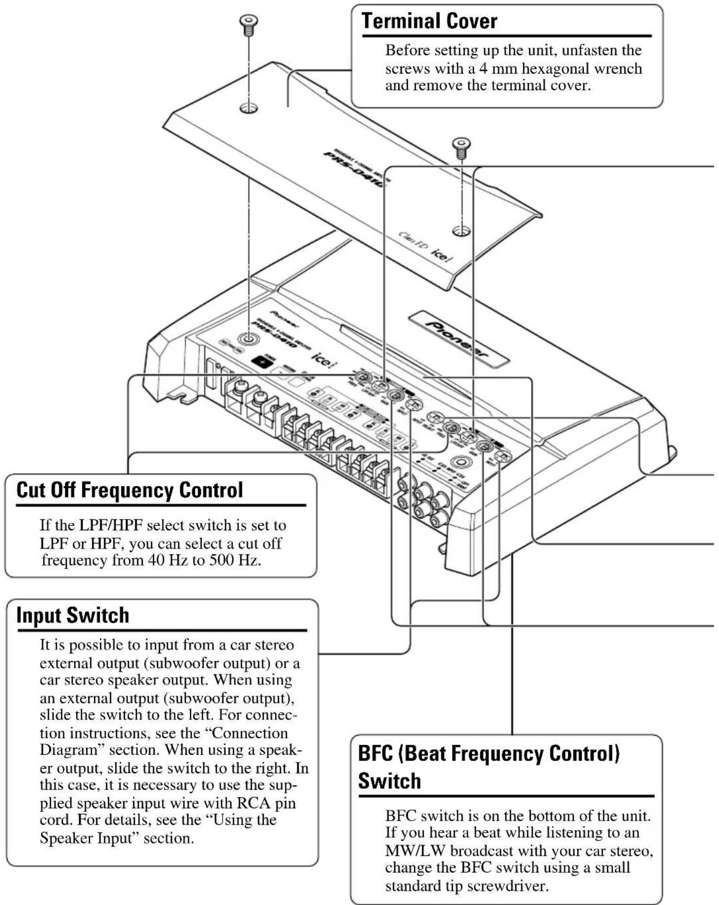
Terminal Cover 3
Cut Off Frequency Control 3
Input Switch 3
BFC (Beat Frequency Control) Switch .... 3
LPF (Low-Pass Filter)/HPF (High-Pass Filter) Select Switch .... 4
Input Select Switch 4
Power Indicator 4
Gain Control 4
Connecting the Unit 5
Connection Diagram 6
Connecting the Power Terminal 7
Connecting the Speaker Output Terminals ..... 8
Using the Speaker Input 8
Connecting the Speakers and Input Wires ..... 9
Installation 11
Example of installation on the floor mat or on the chassis 12
Replacing the terminal cover 12
Specifications 13
oduct
Thank you for purchasing this PIONEER product. Before attempting operation, be sure to read this manual.

If you want to dispose this product, do not mix it with general household waste. There is a separate collection system for used electronic products in accordance with legislation that requires proper treatment, recovery and recycling.
Private households in the 25 member states of the EU, in Switzerland and Norway may return their used electronic products free of charge to designated collection facilities or to a retailer (if you purchase a similar new one).
For countries not mentioned above, please contact your local authorities for the correct method of disposal.
By doing so you will ensure that your disposed product undergoes the necessary treatment, recovery and recycling and thus prevent potential negative effects on the environment and human health.
Visit our website
Visit us at the following site:

- Register your product. We will keep the details of your purchase on file to help you refer to this information in the event of an insurance claim such as loss or theft.
• We offer the latest information about Pioneer Corporation on our website.
In case of trouble
When the unit does not operate properly, contact your dealer or the nearest authorized PIONEER Service Station.

CAUTION
Never replace the fuse with one of greater value or rating than the original fuse. Use of an improper fuse could result in overheating and smoke and could cause damage to the product and injury including burns.

CAUTION
Diagram A - Proper
4 Ohm Bridged Mode
Diagram B - Improper
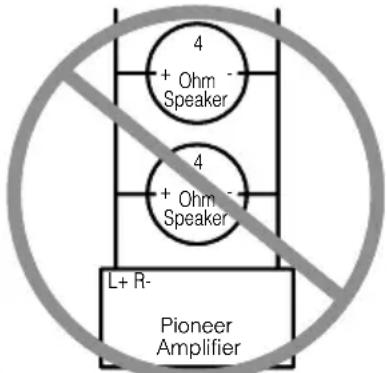
2 Ohm Bridged Mode
Do NOT install or use your Pioneer amplifier by wiring speakers rated at 4 Ohm (or lower) in parallel to achieve a 2 Ohm (or lower) bridged mode (Diagram B).
Amplifier damage, smoke, and overheating could result from improper bridging. The amplifier surface could also become hot to the touch and minor burns could result.
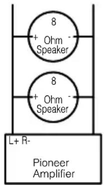
To properly install or use a bridged mode for a two-channel amplifier and achieve a 4 Ω load, wire two 8 Ω speakers in parallel with Left + and Right – (Diagram A) or use a single 4 Ω speaker. For a four-channel amplifier, follow the speaker output connection diagram for bridging as shown on the back of your amplifier, and wire two 8 Ω speakers in parallel to achieve a 4 Ω load or use a single 4 Ω speaker per channel.
If you have any questions or concerns, please contact your local authorized Pioneer dealer or call Pioneer customer service.
WARNING
- Always use the special red battery and ground wire [RD-223], which is sold separately. Connect the battery wire directly to the car battery positive terminal (+) and the ground wire to the car body.
- Do not touch the amplifier with wet hands. Otherwise you may get an electric shock. Also, do not touch the amplifier when it is wet.
- For traffic safety and to maintain safe driving conditions, keep the volume low enough so that you can still hear normal traffic sound.
- Check the connections of the power supply and speakers if the fuse of the separately sold battery wire or the amplifier fuse blows. Detect the cause and solve the problem, then replace the fuse with another one of the same size and rating.
- To prevent malfunction of the amplifier and speakers, the protective circuit will cut the power supply to the amplifier (sound will stop) when an abnormal condition occurs. In such a case, switch the power to the system OFF and check the connection of the power supply and speakers. Detect the cause and solve the problem.
- Contact the dealer if you cannot detect the cause.
- To prevent an electric shock or short-circuit during connection and installation, be sure to disconnect the negative (−) terminal of the battery beforehand.
- Confirm that no parts are behind the panel when drilling a hole for installation of the amplifier. Be sure to protect all cables and important equipment such as fuel lines, brake lines and the electrical wiring from damage.
- DO NOT allow amplifier to come into contact with liquids due to, for example, the location where the amplifier is installed. Electrical shock could result. Also, amplifier and speaker damage, smoke, and overheating could result from contact with liquids. In addition, the amplifier surface and the surface of any attached speakers could become hot to the touch and minor burns could result.
Setting the Unit
- To adjust the switch, use standard tip screwdriver if needed.
LPF (Low-Pass Filter)/HPF (High-Pass Filter) Select Switch
Set the LPF/HPF select switch as follows according to the type of speaker that is connected to the speaker output connector and the car stereo system:
LPF/HPF Select Audio frequency range Speaker Remarks Switch to be output Type
LPF (Left) * — 40 Hz to 500 Hz Subwoofer Connect a subwoofer.
OFF (Center) Full range Full range
HPF (Right) * 40 Hz to 500 Hz — Full range Use if you want to cut the
very low frequency range* because it is not necessary for the speakers you are using.
* See the “Cut Off Frequency Control” section.
Input Select Switch
For two-channel input, slide this switch to the left. For four-channel input, slide this switch to the right.
Power Indicator
The power indicator lights when the power is switched on.
Gain Control
Adjusting the gain controls A and B will help match the output of the car stereo to the Pioneer amplifier. Normally, set the gain controls to the NORMAL position. If the output is low, even when the volume of the car stereo is turned up, turn these controls clockwise. If there is distortion when the volume of the car stereo is turned up, turn these controls counter-clockwise.
- If you only use one input plug, set the gain controls for speaker outputs A and B to the same position.
- When using with an RCA equipped car stereo (standard output of 500 mV), set to the NORMAL position. When using with an RCA equipped Pioneer car stereo with max. output of 4 V or more, adjust level to match the car stereo output level.

CAUTION
- Disconnect the negative (−) terminal of the battery to avoid the risk of short-circuit and damage to the unit.
- Secure the wiring with cable clamps or adhesive tape. To protect the wiring, wrap adhesive tape around it where they lie against metal parts.
-
Do not route wires where they will get hot, for example where the heater will blow over them. If the insulation heats up, it may become damaged, resulting in a short-circuit through the vehicle body.
-
Make sure that wires will not interfere with moving parts of the vehicle, such as the gearshift, handbrake or seat sliding mechanism.
- Do not shorten any wires. Otherwise the protection circuit may fail to work when it should.
- Never feed power to other equipment by cutting the insulation of the power supply wire to tap from the wire. The current capacity of the wire will be exceeded, causing overheating.
- Never replace the fuse with one of greater value or rating than the original fuse. Use of an improper fuse could result in overheating and smoke and could cause damage to the product and injury including burns.

CAUTION:
To prevent damage and/or injury
- Do not ground the speaker wire directly or connect a negative (−) lead wire for several speakers.
- This unit is for vehicles with a 12-volt battery and negative grounding. Before installing it in a recreational vehicle, truck or bus, check the battery voltage.
- If the car stereo is kept on for a long time while the engine is at rest or idling, the battery may go dead. Turn the car stereo off when the engine is at rest or idling.
-
If the system remote control wire of the amplifier is connected to the power terminal through the ignition switch (12 V DC), the amplifier will always be on when the ignition is on—regardless of whether the car stereo is on or off. Because of this, the battery could go dead if the engine is at rest or idling.
-
Speakers to be connected to the amplifier should conform with the standards listed below. If they do not conform, they may catch fire, emit smoke or become damaged. The speaker impedance must be 2 to 8 ohms. But in case of two-channel and other bridge connections, the speaker impedance must be 4 to 8 ohms.
- Install and route the separately sold battery wire as far away as possible from the speaker wires. Install and route the separately sold battery wire, ground wire, speaker wires and the amplifier as far away as possible from the antenna, antenna cable and tuner.
- Cords for this product and those for other products may be different colors even if they have the same function. When connecting this product to another product, refer to the supplied manuals of both products and connect cords that have the same function.
Speaker Channel Speaker Type Power
| Four-channel | Subwoofer Nominal input: Min. 70 W |
| Other than subwoofer Max. input: Min. 150 W | |
| Two-channel | Subwoofer Nominal input: Min. 200 W |
| Other than subwoofer Max. input: Min. 600 W | |
| Three-channel Subwoofer | Nominal input: Min. 70 W |
| Speaker output A | Other than subwoofer Max. input: Min. 150 W |
| Three-channel Subwoofer | Nominal input: Min. 200 W |
| Speaker output B | Other than subwoofer Max. input: Min. 600 W |
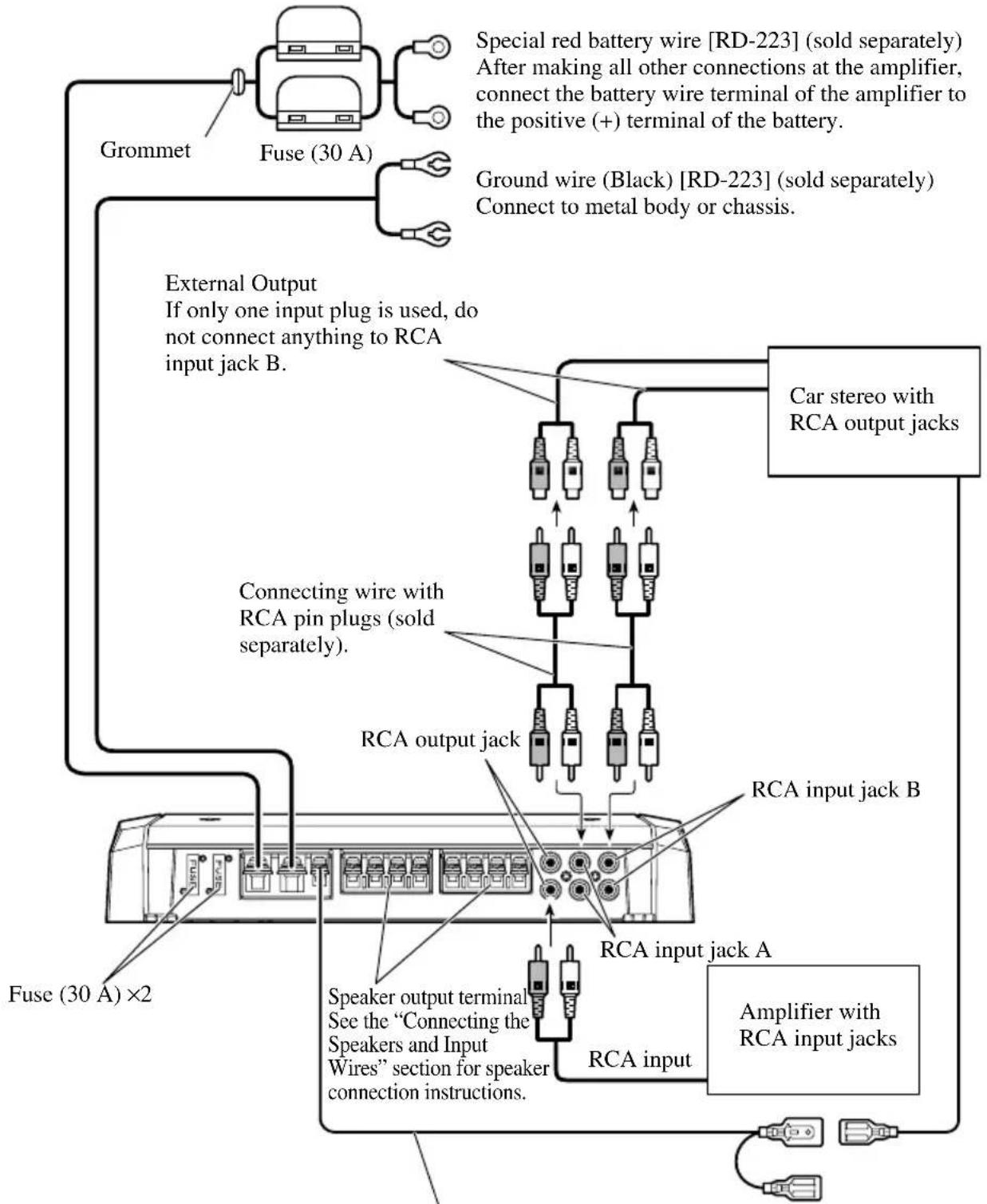
Connection Diagram
- This diagram shows connections using external output (subwoofer output). Slide the input switch to the left.
- When you connect with speaker output, connections defers from the diagram. For details, see the “Using the Speaker Input” section. In either case, you need to set the input switch. For details, see the “Setting the Unit” section.
Fuse (30 A)
flowchart
graph TD
    A["Grommet"] --> B["Fuse (30 A)"]
    B --> C["External Output"]
    C --> D["Car stereo with RCA output jacks"]
    D --> E["RCA input jack A"]
    E --> F["RCA input jack B"]
    F --> G["RCA output jack"]
    G --> H["Speaker output terminal"]
    H --> I["See the “Connecting the Speakers and Input Wires” section for speaker connection instructions."]
    I --> J["RCA input"]
    J --> K["Amplifier with RCA input jacks"]
    K --> L["Fuse (30 A) ×2"]
    L --> M["Connecting wire with RCA pin plugs (sold separately)."]
    M --> N["Car stereo with RCA output jacks"]
    N --> O["Special red battery wire [RD-223"] (sold separately). After making all other connections at the amplifier, connect the battery wire terminal of the amplifier to the positive (+) terminal of the battery.]
    O --> P["Ground wire (Black) [RD-223"] (sold separately). Connect to metal body or chassis.]
System remote control wire (sold separately)
Connect the male terminal of this wire to the system remote control terminal of the car stereo (SYSTEM REMOTE CONTROL). The female terminal can be connected to the auto-antenna relay control terminal. If the car stereo does not have a system remote control terminal, connect the male terminal to the power terminal through the ignition switch.
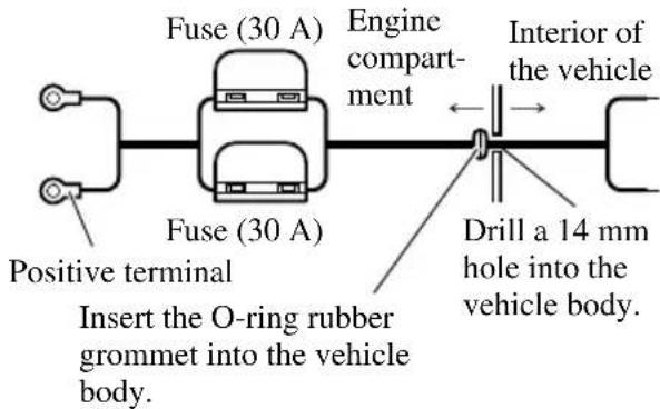
Connecting the Power Terminal
• Always use the special red battery and ground wire [RD-223], which is sold separately. Connect the battery wire directly to the car battery positive terminal (+) and the ground wire to the car body.
1. Pass the battery wire from the engine compartment to the interior of the vehicle.
• After making all other connections to the amplifier, connect the battery wire terminal of the amplifier to the positive (+) terminal of the battery.
2. Twist the battery wire, ground wire and system remote control wire.

3. Attach lugs to wire ends. Lugs not supplied.
- Use pliers, etc., to crimp lugs to wires.
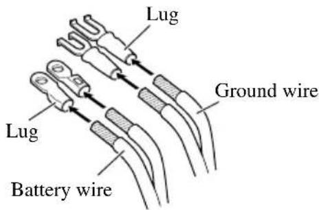
4. Connect the wires to the terminal.
- Fix the wires securely with the terminal screws.
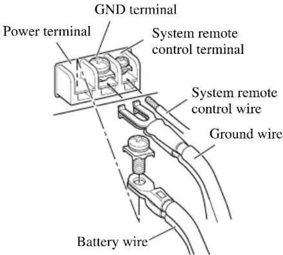
WARNING
Failure to securely fasten the battery wire to the terminal using the terminal screws could cause the terminal area to overheat and could result in damage and injury including minor burns.
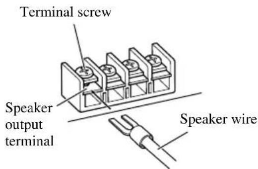
Connecting the Speaker Output Terminals
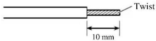
- Expose the end of the speaker wires using nippers or a cutter by about 10 mm and twist.
- Attach lugs to speaker wire ends. Lugs not supplied.
- Use pliers, etc., to crimp lugs to wires.
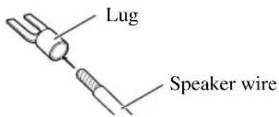
- Connect the speaker wires to the speaker output terminals.
• Fix the speaker wires securely with the terminal screws.
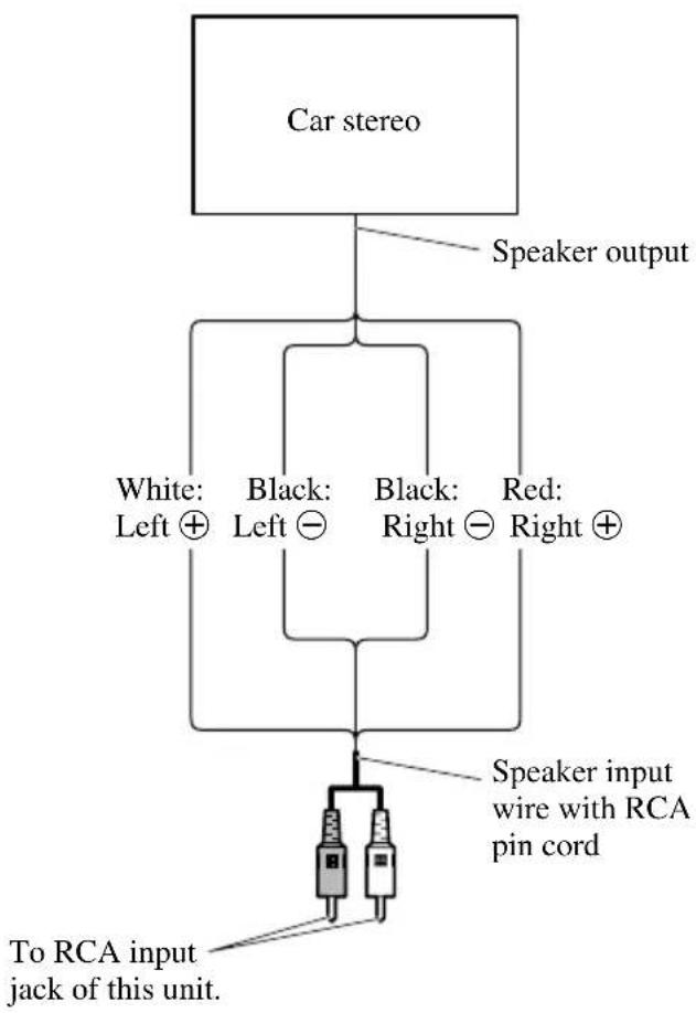
Using the Speaker Input
Connect the car stereo speaker output wires to the amplifier using the supplied speaker input wire with RCA pin cord.
- Slide the input switch to the right.
- For four-channel input, connect two speaker input wires with RCA pin cord to RCA input jack A and B. Be sure to slide the input select switch to the right.
- For two-channel input, connect the speaker input wire with RCA pin cord to RCA input jack A. Do not connect anything to RCA input jack B. Be sure to slide the input select switch to the left.
■Connections when using the speaker input
flowchart
graph TD
    A["Car stereo"] --> B["Speaker output"]
    B --> C["White: Left ⊕ Black: Left ⊖ Black: Right ⊖ Red: Right ⊕"]
    C --> D["Speaker input wire with RCA pin cord"]
    D --> E["To RCA input jack of this unit."]
- As a result of connecting the car stereo speaker output wire to the amplifier, the power of the amplifier is turned on automatically when the car stereo is turned on. It is not necessary to connect the system remote control wire in this case.
Note:
- Connect the system remote control wire when the power of the amplifier is not to be turned on when the car stereo is turned on.
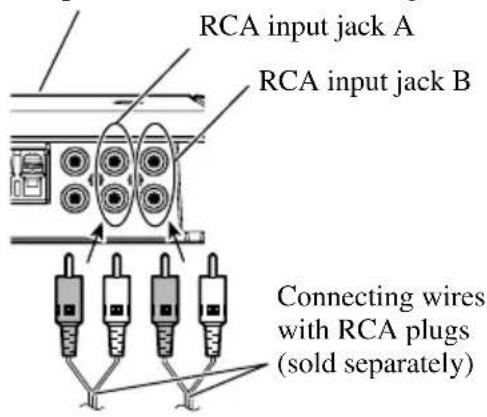
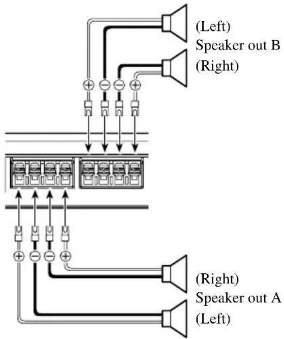
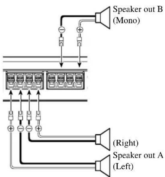
Connecting the Speakers and Input Wires
The speaker output mode can be four-channel, three-channel (stereo + mono) or two-channel (stereo, mono). Connect the speaker leads to suit the mode according to the figures shown below.
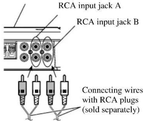
Four-channel
Input select switch is on the top of the unit. For two-channel input, slide this switch to the left. For four-channel input, slide this switch to the right.
From car stereo (RCA output) If only one input plug is used, such as when the car stereo has only one output (RCA output), connect the plug to RCA input jack A, but do not connect a plug to RCA input jack B.
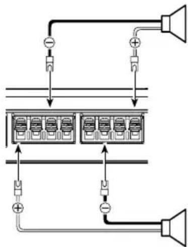
Three-channel
Input select switch is on the top of the unit. For two-channel input, slide this switch to the left. For four-channel input, slide this switch to the right.
From car stereo (RCA output) If only one input plug is used, such as when the car stereo has only one output (RCA output), connect the plug to RCA input jack A, but do not connect a plug to RCA input jack B.
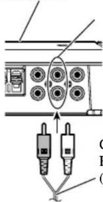
Two-channel (Stereo)
Input select switch is on the top of the unit. Slide this switch to the left.

From car stereo (RCA output)
RCA input jack A In the case of two-channel mode connect RCA plugs to the RCA input jack A.
Connecting wire with RCA plugs (sold separately)
flowchart
graph TD
    A["Speaker"] --> B["Battery Pack"]
    B --> C["Power Supply"]
    C --> D["+/-"]
    D --> E["Ground"]
    style A fill:#f9f,stroke:#333
    style B fill:#ccf,stroke:#333
    style C fill:#cfc,stroke:#333
    style D fill:#fcc,stroke:#333
Speaker (Right)
Speaker (Left)
Two-channel (Mono)
Input select switch is on the top of the unit. Slide this switch to the left.
From car stereo (RCA output)
RCA input jack A In the case of two-channel mode connect RCA plugs to the RCA input jack A.
Connecting wire with RCA plugs (sold separately)

Speaker (Mono)
Speaker (Mono)

CAUTION
- Do not install in:
—Places where it could injure the driver or passengers if the vehicle stops suddenly.
—Places where it may interfere with the driver, such as on the floor in front of the driver's seat.
- Make sure that wires are not caught in the sliding mechanism of the seats, resulting in a short-circuit.
- Confirm that no parts are behind the panel when drilling a hole for installation of the amplifier. Protect all cables and important equipment such as fuel lines, brake lines and electrical wiring from damage.
- Install tapping screws in such a way that the screw tip does not touch any wire. This is important to prevent wires from being cut by vibration of the car, which can result in fire.
- DO NOT allow amplifier to come into contact with liquids due to, for example, the location where the amplifier is installed. Electrical shock could result. Also, amplifier and speaker damage, smoke, and overheating could result from contact with liquids. In addition, the amplifier surface and the surface of any attached speakers could become hot to the touch and minor burns could result.
- To ensure proper installation, use the supplied parts in the manner specified. If any parts other than the supplied ones are used, they may damage internal parts of the amplifier, or they may become loose causing the amplifier to shut down.
- Never replace the fuse with one of greater value or rating than the original fuse. Use of an improper fuse could result in overheating and smoke and could cause damage to the product and injury including burns.

CAUTION:
To prevent malfunction and/or injury
- To ensure proper heat dissipation of the amplifier, be sure of the following during installation.
—Allow adequate space above the amplifier for proper ventilation.
—Do not cover the amplifier with a floor mat or carpet.
- DO NOT allow amplifier to come into contact with liquids due to, for example, the location where the amplifier is installed. Electrical shock could result. Also, amplifier and speaker damage, smoke, and overheating could result from contact with liquids. In addition, the amplifier surface and the surface of any attached speakers could
become hot to the touch and minor burns could result.
- Do not install the amplifier on unstable places such as the spare tire board.
- The best location for installation differs with the car model and installation location. Secure the amplifier at a sufficiently rigid location.
- Make temporary connections first and check that the amplifier and the system operate properly.
- After installing the amplifier, confirm that the spare tire, jack and tools can be easily removed.
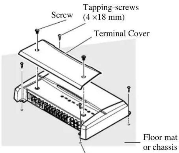
Example of installation on the floor mat or on the chassis
- Place the amplifier where it is to be installed. Insert the supplied tapping screws (4 × 18 mm) into the screw holes. Push on the screws with a screwdriver so they make marks where the installation holes are to be located.
- Drill 2.5 mm diameter holes at the point marked, and install the amplifier, either on the carpet or directly to the chassis.
Replacing the terminal cover
- Align the unit and terminal cover, and insert the screw.
- Tighten the screw with a 4 mm hexagonal wrench.
Drill a 2.5 mm diameter hole
Specifications
Power source 14.4 V DC (10.8 V to 15.1 V allowable)
Grounding system ...... Negative type
Current consumption 28 A (at continuous power, 4 Ω)
Average current drawn* 10 A (4 Ω for four channels)
20 A (4 Ω for two channels)
20 A (2 Ω for four channels)
Fuse 30 A × 2
Dimensions 304 (W) × 56 (H) × 195 (D) mm
Weight 3.0 kg (Leads for wiring not included)
Maximum power output 150 W × 4 (4 Ω) / 600 W × 2 (4 Ω)
Continuous power output 75 W × 4 (at 14.4 V, 4 Ω, 20 Hz to 20 kHz 1.0% THD)
300 W ×2 (at 14.4 V, 4 Ω, 1 kHz 1.0% THD)
150 W ×4 (at 14.4 V, 2 Ω, 1 kHz 1.0% THD)
Load impedance 4 Ω (2 Ω to 8 Ω allowable)
(Bridge connection: 4 Ω to 8 Ω allowable)
Frequency response 10 Hz to 50 kHz (+0 dB, -3 dB)
Signal-to-noise ratio 100 dB (IEC-A network)
Distortion 0.005% (10 W, 1 kHz)
Separation 70 dB (1 kHz)
60 dB (100 Hz to 10 kHz)
Low pass filter Cut off frequency: 40 Hz to 500 Hz
Cut off slope: -12 dB/oct
High pass filter .... Cut off frequency: 40 Hz to 500 Hz
Cut off slope: -12 dB/oct
Gain control RCA: 400 mV to 6.5 V
Speaker: 1.6 V to 26 V
Maximum input level / impedance RCA: 6.5 V / 22 kΩ
Speaker: 26 V / 90 kΩ
Note:
- Specifications and the design are subject to possible modification without notice due to improvements.
\*Average current drawn
- The average current drawn is nearly the maximum current drawn by this unit when an audio signal is input. Use this value when working out total current drawn by multiple power amplifiers.
natural_image
Diagram of two connectors with pins and connecting wires, no text or symbols presentLuidsprekeruitgang B (Mono)
Visit www.pioneer.co.uk (or www.pioneer-eur.com) to register your product.
PIONEER ELECTRONICS (USA) INC.
P.O. Box 1540, Long Beach, California 90801-1540, U.S.A.
TEL: (800) 421-1404
PIONEER EUROPE NV
Haven 1087, Keetberglaan 1, B-9120 Melsele, Belgium
TEL: (0) 3/570.05.11
PIONEER ELECTRONICS ASIACENTRE PTE. LTD.
253 Alexandra Road, #04-01, Singapore 159936
TEL: 65-6472-7555
PIONEER ELECTRONICS AUSTRALIA PTY. LTD.
178-184 Boundary Road, Braeside, Victoria 3195, Australia
TEL: (03) 9586-6300
PIONEER ELECTRONICS OF CANADA, INC.
300 Allstate Parkway, Markham, Ontario L3R OP2, Canada
TEL: 1-877-283-5901
PIONEER ELECTRONICS DE MEXICO, S.A. de C.V.
Blvd.Manuel Avila Camacho 138 10 piso
Col.Lomas de Chapultepec, Mexico, D.F. 11000
TEL: 55-9178-4270
Published by Pioneer Corporation.
Copyright © 2006 by Pioneer Corporation.
All rights reserved.
Publication de Pioneer Corporation.
Copyright © 2006 Pioneer Corporation.