
Jockey III Master Edition - Mixer Reloop - Free user manual and instructions
Find the device manual for free Jockey III Master Edition Reloop in PDF.

User questions about Jockey III Master Edition Reloop
0 question about this device. Answer the ones you know or ask your own.
Ask a new question about this device
Download the instructions for your Mixer in PDF format for free! Find your manual Jockey III Master Edition - Reloop and take your electronic device back in hand. On this page are published all the documents necessary for the use of your device. Jockey III Master Edition by Reloop.
USER MANUAL Jockey III Master Edition Reloop
Professional 4 deck MIDI controller with integrated 4 channel soundcard
r your own safety, please read this operation manual carefully before initial operation! All persons involved in the installation, setting-up, operation, maintenance and service of this device must be appropriately qualified and oerve this operation manual in detail. This product complies with the requirements of the applicable European and national regulations. Conformity has been proven. The respective statements and documents are deposited at the manufacturer.
Mode d'emploi
ATTENTION!
To prevent fire or avoid an electric shock do not expose the device to water or flu. Never open the housing!
ATTENTION!
Keep information for further reference!
- Updates & Support 23
6.1 Firmware-Update 23-25
6.2.Treiber-Update 25
6.3. Mappings 25
7.Anhang 25
| Device In-Port Out-Port | ||
| Jockey 3 V* (Deck A) Reloop Jockey 3 | ||
| Jockey 3 V* (Deck B) Reloop Jockey 3 | ||
| Jockey 3 V* (Deck C) Reloop Jockey 3 | ||
| Jockey 3 V* (Deck D) Reloop Jockey 3 | ||
| Jockey 3 V* (Mixer) Reloop Jockey 3 | ||
| Jockey 3 V* (FX Presets) | Reloop Jockey 3 Reloop Jockey 3 |
4. BEDIENUNG
Control Change messages are sent with status OxBn, where n is the channel, for the specified CC controller. Thus the controller MIDI ID is indicated with the channel along with the CC number. The value from 0x00 to 0x7F, directly related to the location of the controller.
CC-RELATIVE (ENC)
Control Change messages are status OxBn, where n is the channel, for the specified CC controller. Thus the controller MIDI ID is indicated with the channel along with the CC number. The value from Ox40 to indicate the change in the controller. This is an offset to Ox40 "one's complement" notation. A message with data Ox43 indicates a positive change of 3. A messages with data Ox31 indicates a negative change of 15.
SWITCH ON/OFF (SW,CENTER,CW,CCW)
These messages are used for switches.
Control Change messages are sent with status Ox9n, SWITCH On and Off value are Ox7F and Ox00, where n is the channel.
LED ON/OFF (LED)
These messages are used for LED.
Control Change messages are sent with status 0x9n , LED On and Off value are 0x7F and 0x00 , where n is the channel.
PITCHBEND
Pitchbend messages are status OxEn, where n is the channel, for the specified controller.
Thus the controller ID is indicated only by the channel.
For accurate changes, the 14 bit data in a pitch bend message is reserved for absolute controllers which require more than 7 bits of data.
LEVELLED (LEVEL)
These messages are used for LEVEL.
Control Change messages are sent with status 0x9n LED Off value is 0x00 and On value is related to LED amount, 0x01 with one LED, 0x02 with two LED..., where n is the channel.
2.1 Output Level: (Sony Sound Audio Dev Ice Type: Jockey 3 ME)
Master OUT: -9 dBV +/-2dB (TCD782 TRK16)
Phones OUT: -10dBV +/2dB (TCD782 TRK16)
2.2 Frequenzgang: (Sony Sound Audio Device Type: Windows classic Wave Driver)
Master OUT: 17-16 kHz +/-1,5dB (TCD782 TRK1, 4, 16)
2.3 THD+N: (Sony Sound Audio Device Type: Windows classic Wave Driver)
Master OUT: < 0,01% (TCD782 TRK2, Master VR OUT: 0dB)
Master OUT: .01% (96K-TDC782 TRK2, Master VR OUT: 0dB)
2.4 S/N Ratio: (Sony Sound Audio Device Type: Windows classic Wave Driver)
Master OUT: 95dB (TCD782 TRK2, 8; Master VR OUT: 0dB)
2.5 LR Trennung: (Sony Sound Audio Device Type: Windows classic Wave Driver)
Master OUT: 85dB (TCD782 TRT9, 11)
3 Recording und Playback (Line 1Khz, OdDV, MIC 1KHz -36dB Input, 44.1K Sample Rate 24bit)
3.1 Output+3dBV (1.41V) +/- 1.5dB
THD+N. .02% (w/20KHz LPF, A-weighted)
THD + N .0.02% (w/20KHz LPF, A-weighted 96K Sample Rate 24bit)
3.2 S/N Ratio+3dBV (1.41V) +/- 1.5dB
Line: 82dB
Mic: .>70dB
For your own safety, please read this operation manual carefully before initial operation! All persons involved in the installation, setting-up, operation, maintenance and service of this device must be appropriately qualified and follow this operation manual in detail. This product complies with the requirements of the applicable European and national regulations. Conformity has been proven. The respective statements and documents are deposited at the manufacturer.
INDEX
- Setup 33
1.1. Control Elements 33-34
1.2. Connections 35-36
-
Initial Operation. 36
-
Computer Configuration 36
3.1. ASIO Driver Installation 36-38
3.2. Traktor LE Setup 38
3.2.1.Installation 38
3.2.2. Configuration 38-40
3.3. Traktor PRO Configuration (if applicable). 40
3.3.1. Audio-Setup 40
3.3.2.Mapping-Import 41-42
- Operation 43
4.1. Traktor Function Assignment 43-46
4.2. Routing Functions 47
4.2.1.Microphone 47-48
4.2.2 Inputs. 48-50
4.3. Analog Mixing Function 50
4.4. Outputs 50
4.5. Master-Thru und CUE-Master-Thru 50
5. Device Settings & Tests 50
5.1. Menu for MIDI Channel Assignment and 50 Jog Wheel Resolution Adjustments
5.1.1.MIDI Channel Assignment.. 51
5.1.2.Jog Wheel Resolution 51
5.2. LED Function Test 51
5.3.Auto Setup 52
5.4.Firmware Version Check. 52
5.5.JogDrag 52
5.6.Jog Sensitivity 52
5.7. LED Dimmer 52
- Updates & Support 52
6.1 Firmware-Update 52-54
6.2.Driver Update 54
6.3. Mappings. 54
- Appendix 54
7.1. System Requirements Traktor LE 54
7.2.MIDI Assignment Chart.. 54-56
7.3. Troubleshooting 57
7.4. Technical Specifications 58
Congratulations on purchasing the Reloop Jockey 3 Master Edition. Thank you for placing your trust in our disc jockey technology. Before operating this equipment we ask you to carefully study and observe all instructions.
Please remove the Reloop Jockey 3 Master Edition from its packaging. Before initial operation please make sure that the device has not been visibly damaged during transport. If you detect any damage to the power cable or the casing, do not operate the device and contact your specialised dealer.
SAFETY INSTRUCTIONS

CAUTION!
Please exercise particular caution when handling power voltage. This voltage rating may lead to a critical electrical shock! Any damage caused by the non-observance of this operation manual excludes any warranty claims. The manufacturer is not liable for any damage to property or for personal injury caused by improper handling or non-observance of the safety instructions.
- This device has left the factory in perfect condition. To maintain this condition and to ensure a risk-free operation the user must observe the safety instructions and warnings contained in this operation manual.
- For reasons of safety and certification (CE) the unauthorised conversion and/or modification of the device is prohibited. Please note that in the event of damage caused by the manual modification to this device any warranty claims are excluded.
- The inside of the device does not contain any parts which require maintenance, with the exception of wear parts that can be exchanged from the outside. Only qualified staff must carry out maintenance, otherwise warranty does not apply!
- The fuse must exclusively be exchanged against fuses of the same class, with the same trigger features and nominal current rating.
- Make sure that the power will only be supplied after the device has been fully set up. Always plug in the mains plug last. Ensure that the mains switch is in the "OFF" position when connecting the device to power.
- Only use cables that comply with regulations. Make sure that all jacks and bushes are tightened and correctly hooked up. Refer to your dealer if you have any questions.
- Ensure that when setting up the product the mains cable is not squashed or damaged by sharp edges.
- Prevent the mains cable from coming into contact with other cables! Exercise great care when handling mains cables and connections. Never touch these parts with wet hands!
- Connect the power cable exclusively to appropriate shock-proof outlets. The only supply point to be used is a supply outlet in accordance with specifications of the public supply network.
- Disconnect the device from the supply outlet when not in use and before cleaning! Be sure to hold the mains plug by the body. Never pull the mains cord!
- Position the device on a horizontal and stable low-flame base.
- Avoid any concussions or violent impact when installing or operating the device.
- When selecting the location of installation make sure that the device is not exposed to excessive heat, humidity, and dust. Be sure that no cables lie around openly. You will endanger your own safety and that of others!
- Do not rest any containers filled with liquid that could easily spill onto the device or in its immediate vicinity. If, however, fluids should access the inside of the device, immediately disconnect the mains plug. Have the device checked by a qualified service technician before re-use. Damage caused by fluids inside the device is excluded from the warranty.
- Do not operate the device under extremely hot (in excess of 35^ ) or extremely cold (below 5^ ) conditions. Keep the device away from direct exposure to the sun and heat sources such as radiators, ovens, etc. (even · during transport in a closed vehicle). Never cover the cooling fan or vents. Always ensure sufficient ventilation.
- The device must not be operated after being taken from a cold environment into a warm environment. The condensation caused hereby may destroy your device. Do not switch on or operate the device until it has reached · ambient temperature!
- Controls and switches should never be treated with spray-on cleaning agents and lubricants. This device should only be cleaned with a damp cloth. Never use solvents or cleaning fluids with a petroleum base for cleaning.
- When relocating, the device should be transported in its original packaging.
- When starting operation, the faders and volume controls of your amplifier must be set to minimum level. Bring the loudspeaker switches into the "OFF" position. Wait between 8 to 10 seconds before increasing the volume to avoid shot noise created by transient effect, which could cause damage to loudspeakers and the diplexer.
Devices supplied by voltage should not be left in the hands of children. Please exercise particular care when in the presence of children. - At commercial facilities the regulations for the prevention of accidents as stipulated by the organization of professional associations must be observed.
- At schools, training facilities, hobby and self-help workshops the operation of the device must be monitored with responsibility by trained staff.
- Keep this operation manual in a safe place for later reference in the event of questions or problems.
APPLICATION IN ACCORDANCE WITH REGULATIONS
- This device is a professional DJ MIDI controller with integrated 6-In / 4-Out soundcard that can control software. The device should be connected via USB cable to a computer.
- This product is authorised for connection to 240 V, 50 Hz AC via the included mains adapter and is designed exclusively for indoor application.
- If the device is used for any other purposes than those described in the operation manual, damage can be caused to the product, leading to exclusion of warranty rights. Moreover, any other application that does not comply with the specified purpose harbours risks such as short circuit, fire, electrical shock, etc.
- The serial number determined by the manufacturer must never be removed to uphold the warranty rights.
MAINTENANCE
- Check the technical safety of the device regularly for damage to the mains cord or the casing, as well as for wearout of wear parts such as rotary knobs and sliding faders.
- If it is to be assumed that a safe operation is no longer feasible then the device must be disconnected and secured against accidental use. Always disconnect the mains plug from the outlet!
- It must be assumed that a safe operation is no longer feasible if the device bears visible defects, if the device no longer functions, following longer storage under unfavourable conditions or after major transport stress.
1. SETUP
1.1. CONTROL ELEMENTS
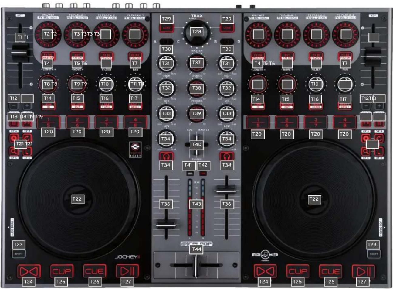
Surface
| # Designation Shift Designation | ||
| T01 Pitchfader Key | ||
| T02 Dry/Wet Control Effect change in Advanced Effect Mode | ||
| T03 Effektparameter Effect change in Chained Effect Mode | ||
| T04 FX On Button FX Preset 1 | ||
| T05 Effect Reset and FX 1 On respectively | FX Preset 2 | |
| T06 Effect Button 1 and FX 2 On respectively | FX Preset 3 | |
| T07 Effect Button 2 and FX 3 On respectively | FX Preset 4 | |
| T08 Loop Length | ||
| T09 Loop Shift | ||
| T10 Filter | ||
| T11 Pan (Balance) Control | ||
| T12 Pitch Bend Button - FX | ||
| T13 Pitch Bend Button + FX | ||
| T14 Auto-loop Function | Loop In/Set Cue Button | |
| T15 Reloop Function | Loop Out Button | |
| T16 Beatjump Backward | Left-Sided GRID Shift | |
| T17 Beatjump Forward | Right-Sided GRID Shift | |
| T18 Hot Cue Delete Button | ||
| T19 Hot Cue Bank Select | ||
| T20 Hot Cue Buttons | Sample Player 1 - 8 | |
| T21 Jog Wheel Mode Buttons | ||
| T22 Jog Wheel | ||
| T23 Shift Button | ||
| T24 Sync Button | Deck Master Select | |
| T25 Cup Button | Beat Tab | |
| T26 Cue Button | FX Mode | |
| T27 Play/Pause Button | Keylock | |
| T28 TRAX Encoder | Folder Navigation | |
| T29 Load Button | Preferences Folder Navigation | |
| T30 Deck Select Switch | ||
| T31 Gain Control | ||
| T32 EQ Control High | ||
| T33 EQ Control Mid | ||
| T34 EQ Control Low | ||
| T35 Monitor Cue Button | Preview-Player Load&Play and Stopp respectively | |
| T36 Linefader | ||
| T37 Master Volume | ||
| T38 Booth Volume | ||
| T39 Headphones Volume | ||
| T40 Cue Mix Fading | ||
| T41 Power LED | ||
| T42 MIDI Signal LED | ||
| T43 VU-Meter | ||
| T44 Crossfader | ||
1.2. CONNECTIONS
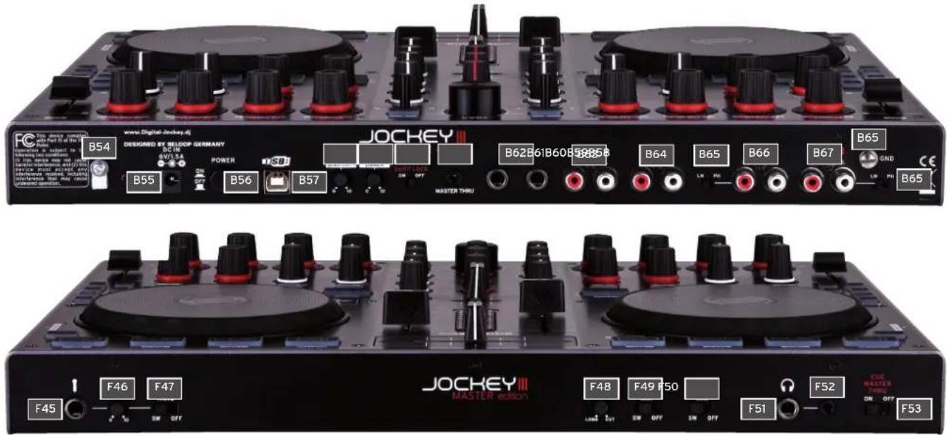
Rear Side
| # Designation |
| B54 Mains Cord Strain Relief |
| B55 Mains Adapter Connection (DC 6V/1,5A) |
| B56 ON/OFF Switch |
| B57 USB Port |
| B58 Jog Wheel Sensitivity |
| B59 LED Dimmer |
| B60 Shift Lock Switch |
| B61 3.5 mm Jack Master-Thru Input |
| B62 6.3 mm Jack Master 2 Audio Output (balanced) |
| B63 RCA Master 1 Audio Output |
| B64 RCA Booth Audio Output |
| B65 Line/Phono Switch |
| B66 RCA Input 2 |
| B67 RCA Input 1 |
| B68 Grounding Screw |
Front Side
| # Designation |
| F45 6.3 mm Jack Microphone Connection |
| F46 Microphone Volume |
| F47 Microphone Routing Switch |
| F48 Crossfader Curve |
| F49 Input 1 Routing Switch |
| F50 Input 2 Routing |
| F51 6.3 mm Jack Headphones Connection |
| F52 3.5 mm Jack Headphones Connection |
| F53 Master Thru Routing Switch |
Lateral View
| # Designation |
| S69 Jog Wheel Drag |
| S70 Kensington Lock |
- First make sure to turn off the device via the ON/OFF Button -B56- on the rear panel.
- Connect the included mains adapter to the device's DC jack -B55- and a shock-proof outlet.
- Then connect the included USB cable to the corresponding connection -B57- on the device's rear panel and a free USB port of your computer.
3.COMPUTER CONFIGURATION
Before you can use your new device a few basic computer adjustments have to be carried out.
ATTENTION!

Please make sure that your Reloop Jockey 3 is still turned off. You will be asked during the installation to turn the device on.
The included USB cable can already be connected.
Please pay special attention to the following explanations.
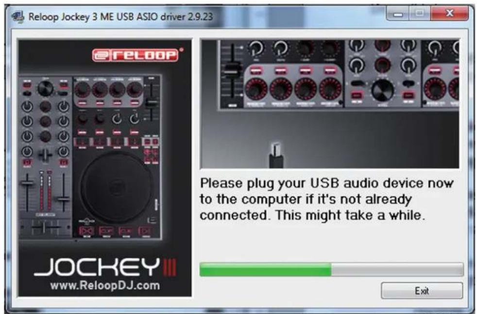
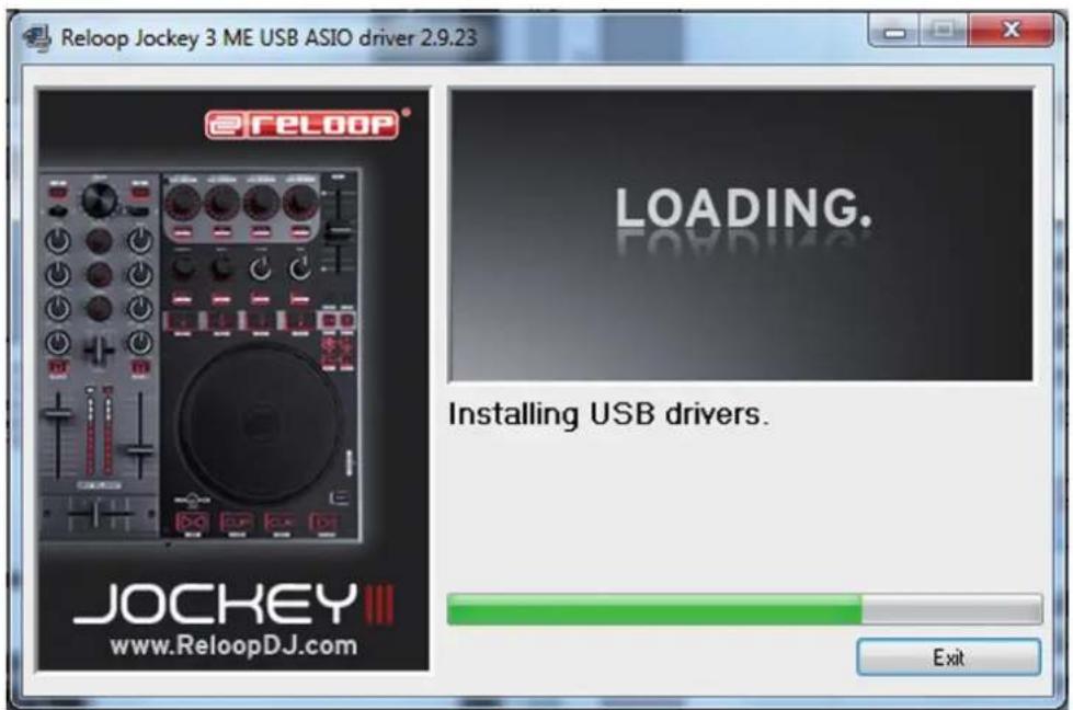
3.1 ASIO DRIVER INSTALLATION
Insert the included installation CD in your computer's drive. Select the driver that best suits your system in the „Drivers" folder and start the installation via a double click.
TIPI!
Reloop regularly provides updated drivers online. For more information please read the chapter „Updates & Support".

NOTE!
Please make sure to start the driver installation with admin rights. Otherwise the installation will fail with an error message.
When using Windows Vista or Windows 7 please carry out the appropriate installation setup via a click of the right mouse button. Then select „Run as admin".
- First of all you will enter the language select window. Please select your preferred language.

- Now click on the „Install the driver" button.

- You will then be asked to connect and turn on your Reloop Jockey 3.If your Reloop Jockey 3 is not connected via USB yet, please connect the included USB cable to the USB port -B57- and a free USB port of your computer. Also connect the included mains adapter to the corresponding connector -B55-. Now turn on the device via the ON/Off Button -B56-.
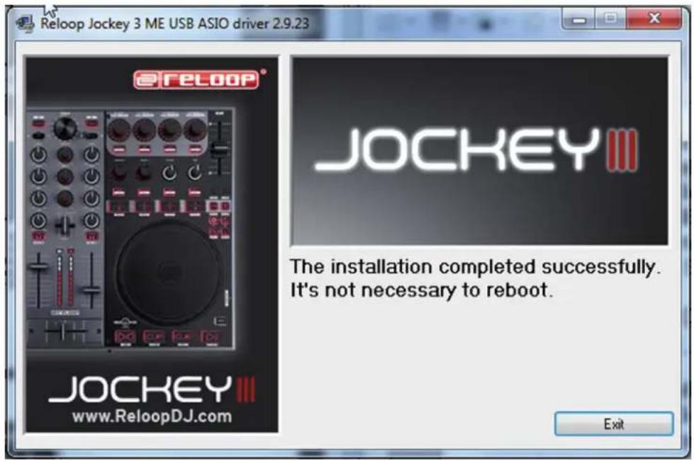
- The installation will be continued. As soon as the installation has been carried out successfully you can close the setup via the „Finish“ button. A reboot is not necessary.
3.2 TRAKTOR LE SETUP
Along with Reloop Jockey 3 you receive the gratuitous and non-restrictive DJ software „Traktor LE".
NOTE!
Upgrade to Traktor Pro (4 deck support):
Via the Included Traktor LE version you can purchase the extensive Traktor Pro version at a bargain price. Current price conditions can be found under www.nativeinstruments.de

3.2.1 INSTALLATION
Besides the ASIO drivers, you can also find a directory named „Traktor" on the included installation CD. Open this directory and select the setup file that best suits your system. Follow the instructions from the installation window.

NOTE!
Details regarding the system requirements can be found in the appendix under the item „System Requirements Traktor LE".
3.2.2 CONFIGURATION
When using Traktor LE for the first time the „Setup Wizard“ should start. If this is not the case please click on „Help“ and select the menu item „Start Setup Wizard“. In the setup wizard select the following items:
- Answer the first question „Are you using a USB/FireWire Controller?" with „Yes". Then click on „Next".
- In the field „Choose your manufacturer" select the item „Reloop". The following menu item „Choose your model" has to be answered with „Jockey 3 Master LE". Again confirm this selection with „Next".
- The following questions regarding connected hardware by manufacturer „Native Instruments" has to be answered with „No".
Your Reloop Jockey 3 should now be configured accordingly for Traktor LE.
By default the audio setup should be adjusted to internal mixing mode. If this is not the case, please pay close attention to the following items
Otherwise you can skip this chapter and continue with the chapter „Operation".
Audio Setup:
Internal Mixing Mode
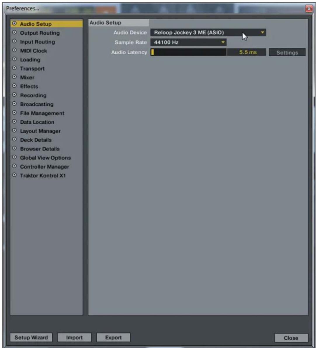
- In Traktor open the setup dialogue by clicking the small cog wheel the upper right corner.
- Open the category „Audio Setup" and in the file „Audio Device" select the item „Reloop Jockey 3".
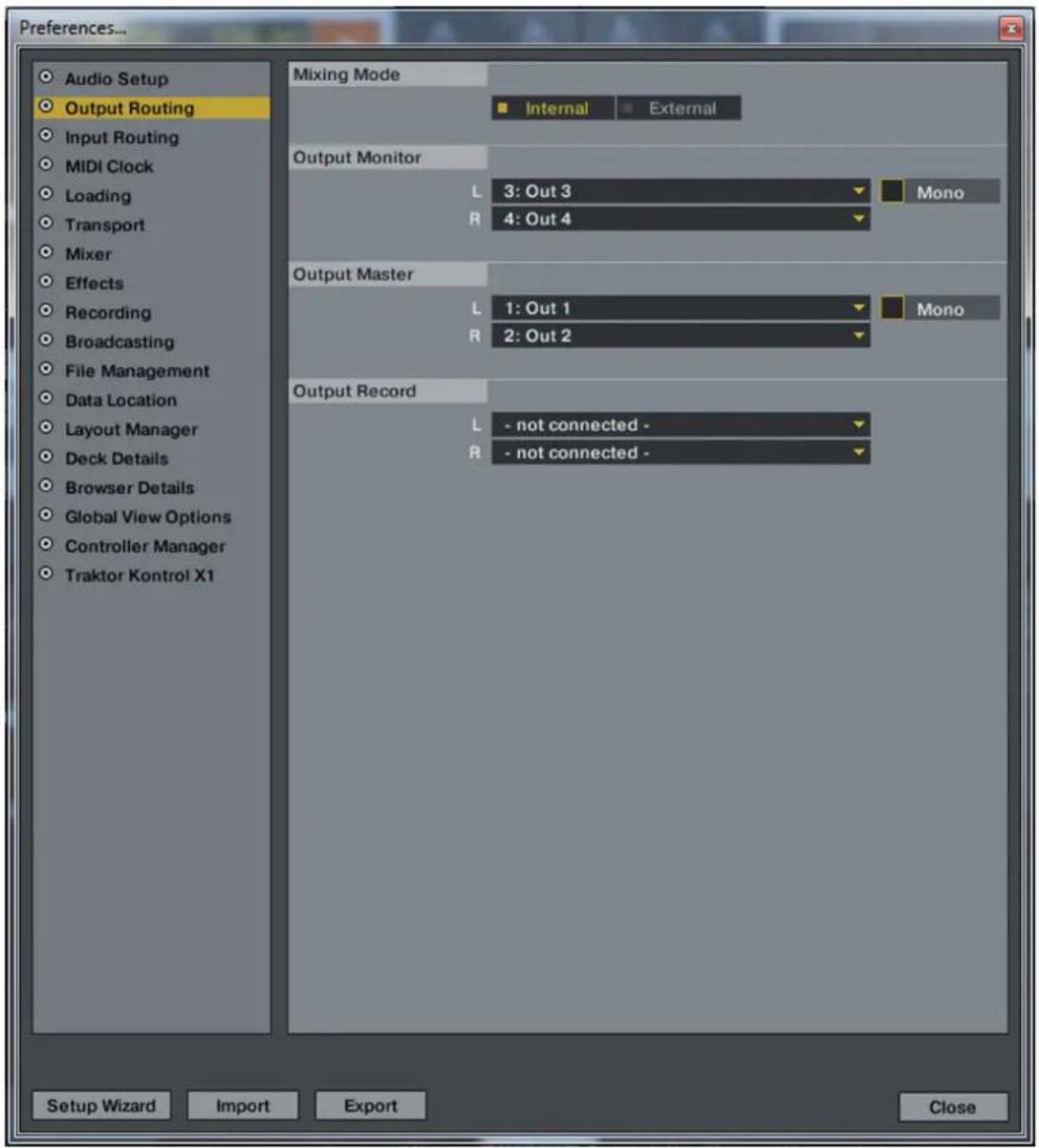
- Open the category „Output Routing" and in the field „Mixing Mode" select the button „Internal". For channel assignment please see the following example.
3.3 TRAKTOR PRO CONFIGURATION (IF APPLICABLE)
If you already possess Traktor Pro or you have upgraded Traktor LE at a lower-cost price, it is possible to fully utilize all Jockey 3 functions.
Pay close attention to the following points in order for Traktor to be able to work in combination with Jockey 3.
3.3.1 AUDIO SETUP
The audio setup does not differ from the Traktor LE audio setup. Please proceed as described under item 3.2.2.
3.3.2 MAPPING IMPORT
In order for Traktor to be able to assign the MIDI commands sent by the Jockey 3 to the correct functions, a special mapping is necessary.
A suitable mapping can be found on the installation CD in the folder „Mappings/Traktor Pro".

NOTE!
You can find updated and extended mappings online. Go to http://www.reloopdj.com/forum and open the category „Mapping files" in the field „Downloads for all Reloop products".
Please proceed as follows in order to import the mapping:
- In Traktor open the adjustment dialogue by clicking the small cog wheel in the upper right corner.
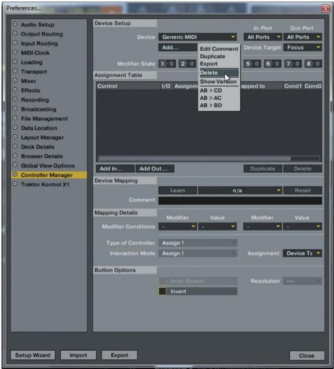
- Open the category „Controller Manager".
- In order to avoid problems it is recommended to delete all existing entries apart from the keyboard mappings from the controller manager: To do so select one entry after the other in the field „Device" and press „EDIT...” followed by „Delete".
- Now select the button .Add...followed by .Import".
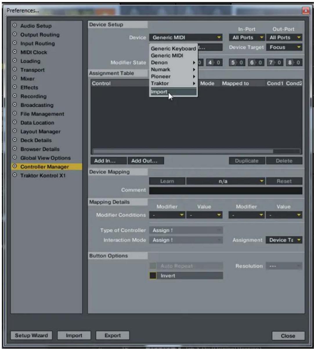
In the select screen open the mapping file that is found on the CD or that was downloaded from the Reloop support site.
Troubleshooting
Should a problem arise and the Jockey 3's LEDs are not lit correctly, in most cases this is probably caused by installed MIDI software (e.g. MidiYoke, Maple VirtualMIDI Cable, OSCulator, Bome Midi Translatoretc.).
In order to solve the problem proceed as follows:
- In Traktor open the adjustment dialogue by clicking the small cog wheel in the upper right corner.
- Open the category „Controller Manager".
- For the following device entries the following port assignments have to be configured:
| Device In-Port Out-Port | ||
| Jockey 3 V* (Deck A) Reloop Jockey 3 | Reloop Jockey 3 | Reloop Jockey 3 |
| Jockey 3 V* (Deck B) Reloop Jockey 3 | Reloop Jockey 3 | Reloop Jockey 3 |
| Jockey 3 V* (Deck C) Reloop Jockey 3 | Reloop Jockey 3 | Reloop Jockey 3 |
| Jockey 3 V* (Deck D) Reloop Jockey 3 | Reloop Jockey 3 | Reloop Jockey 3 |
| Jockey 3 V* (Mixer) Reloop Jockey 3 | Reloop Jockey 3 | Reloop Jockey 3 |
| Jockey 3 V* (FX Presets) Reloop Jockey 3 | Reloop Jockey 3 | Reloop Jockey 3 |
4. OPERATION
After connecting and configuring Reloop Jockey 3 correctly for the DJ software, Traktor can now be used. If Traktor Pro is used, it is possible to fully utilize the Jockey 3 user interface. There are some differences for Traktor LE regarding effect control, the number of usable decks and the hot cue assignment.
4.1 TRAKTOR FUNCTION ASSIGNMENT

NOTE!
In the following the whole Traktor function assignment will be described. Some features are only available in Traktor Pro and therefore they have been marked grey in the following chart.
| Element Funktion Funktion bei aktivem Shift -T3- | ||
| T1 Pitchfader | Herewith it is possible to adjust the current deck's (see -T30-) pitch. | Keyfader Herewith it is possible to adjust the current deck's key. |
| T2 Dry/Wet | Dial With this encoder it is spossible to adjust the effect's intensity. | Effekt Change <Advanced E.>If the Advanced Effect section is selected, it is possible to change the effect by turning the encoder. |
| T3 Effect Par | Parameter <Advanced E.>In Advanced Effect Mode the parameters can be adjusted herewith.Dry/Wet Fine Adjustment <Chained E.>If Chained Effect Mode is used, the single effects can be operated.NOTE! In Traktor LE only the 1st parameter in Chained Effect Mode works. | Effect Change <Chained E.>In Chained Effect Mode it is herewith possible to change the respective effect.NOTE! In Traktor LE only the 1st effect from the effect section works. |
| T4 FX On Button | <Advanced E.>Activates the Advanced FX Section corresponding to the deck (Deck A > FX1, Deck B > FX2, Deck C > FX3, Deck D > FX4) | FX-Preset-1-Taste consists of:Beatmasher 2Digital LoFiReverse Grain |
| T5 Effect Reset | Reset Function <Advanced E.>In Advanced Effect Mode it is possible to reset the effect herewith.FX 1 On <Chained E.>Activates and deactivates the 1st effect in Chained Effect Mode respectively. | FX Preset 1 Button consists of:Beatmasher 2Digital LoFiReverse Gain |
| T6 Effect Button | Button 1 <Advanced E.>Activates and deactivates the Effect Button 1 in Advanced Effect Mode.FX 2 On <Chained E.>Activates and deactivates the 2nd effect in Chained Effect Mode respectively. | FX Preset 3 Button consists of:Beatmasher 2ReverbReverse Gain |
| T7 Effect Button | Button 2 <Advanced E.>Activates and deactivates the Effect Button 2 in Advanced Effect Mode.FX 3 On <Chained E.>Activates and deactivates the 3rd effect in Chained Effect Mode. | FX-Preset-4-Taste consists of:DelayFilterReverb |
| T8 Loop Length | Turning the encoder varies a set loop's length.Pressing the encoder activates and deactivates the Loop Active Function respectively. | |
| T9 Loop Shift | Turning the encoder shifts a set loop's position.Pressing and simultaneously turning the encoder determines the movement's step size. | |
| T10 Filter | Adjusts the filter effect for the active deck. In zero position the filter is automatically turned off. | |
| T11 Pan Dial | Herewith it is possible to adjust the volume assignment for the left and right channel. Zero position corresponds to an equal level on both channels. | |
| T12 Pitchbe | Button Slows down the deck's pitch. | FX Routing Button 1 Herewith it is possible to assign FX Unit 1 to the current deck. |
| T13 Pitchbe | Button Increases the deck's pitch. | FX Routing Button 2 Herewith it is possible to assign FX Unit 2 to the current deck. |
| T14 Autoloop | Function Sets an automatic loop with the set loop length (-T9-) without the need to manually set the loop ending point. | Loop In/Set Cue Button Manually sets a loop's starting point. Simultaneously a cue point will be defined. |
| T15 Reloop | Function Jumps to the last set loop, reactivating it. | Loop Out Button Manually sets a loop's ending point. Now the deck is in loop mode; the set passage will now be continuously repeated. Repressing the button will end loop mode. |
| T16 Beat Jump | Jump Backward Executes a beat jump opposed to playback direction. | Left-Sided GRID Shift Shifts the grid that Traktor puts over the bass line a step to the left. |
| T17 Beat Jump | Jump Forward Executes a beat jump in playback direction. | Left-Sided GRID Shift Shifts the grid that Traktor puts over the bass line a step to the left. |
| T18 Hot Cue | Delete Button While this button is being pressed and held it is possible to delete stored cue points by pressing the corresponding Hot Cue Pads -T20-. The LED corresponding to the respective Pad will go out. | |
| T19 Hot Cue | Bank Select Selects the desired Hot Cue Bank. If the LED is not lit, cue bank 1-4 is selected. Pressing the button „,5-8“ allows the operation of Hot Cues 5-8 via the Hot Cue Buttons -T20-. | |
| T20 Hot Cue | Buttons Herewith it is possible to operate the 8 Hot Cues of a track in Traktor. Depending on the active bank (see -T19-), Hot Cues 1-4 or 5-8 can be selected. If a Hot Cue is unassigned (no LED feedback), it is possible to assign it to the current track's position by pressing one of the Pads -T20-. | |
| Element Funktion | ||
| T21 | Jog Wheel Mode ButtonsThere are 4 modes at your disposal which determine the jog wheel's function.- SCRONTHIf this mode is active, it is possible to scratch the current track as long as the jog wheel's -T22- surface is being touched. If only the side is being touched, the current track's pitch can be increased (clockwise) or decreased (counter-clockwise).- PITCH BENDHerewith it is possible to increase (clockwise) or decrease (counterclockwise) the track's pitch. As opposed to SCRONTH mode the jog wheel's -T28- rotational speed influences a track's manipulation.- SEARCHAllows quick scrolling through a loaded track.- TRAXBy activating this mode Traktor automatically switches to browse view. Now it is possible to navigate comfortably through the track list via the Jog wheel -T22-. A complete navigation in folder as well as track list in Traktor can be executed via the TRAXEncoder -T28-. | Crossfader Select Buttons Via these buttons it is possible to determine which deck is routed to which crossfader side. |
| T22 Jog Wheel | Herewith it is possible to execute various functions. Please refer to the jog wheel mode buttons -T21-. | |
| T23 Shift Button | By pressing this button all the device's control elements receive a different function assign- ment. The current assignment can be viewed on the right side of this chart. | |
| T24 Sync Button | The current track's pitch will be synchronized to the master deck. | Master Deck Assignment The current deck becomes the master deck. |
| T25 Cup Button | As long as this button is being pressed and held, the deck jumps to the last set cue point and stops. Releasing the button will start playback. | Tap Button Determines the track's pitch, de- pending on how quickly the button will be repeatedly pressed. Ideally it should be pressed to every beat should the grid not be fitting. |
| T26 Cue Button | Herewith the cue point will be called up and played as long as the button is being pressed. | FX Mode Button Herewith it is possible to switch between Advanced Effect Mode and Chained Effect Mode. |
| T27 Play/Pause | Starts and pauses the track's playback respec-tivley. | Keylock (De-)activates Keylock. |
| T28 Tracklist | Navigation- By turning the encoder it is possible to scroll through the track list.- By pressing the encoder browse view will be maximized. | Folder Navigation- By turning the encoder it is pos-sible to navigate the folder list.- Pressing the encoder opens and closes the selected folder. |
| T29 Load Buttons | By pressing this button the selected track will be assigned to the respective deck. | Favorites Navigation Via these buttons it is possible to scroll through the favorites. |
| T30 Deck Select SwitchVia this switch it is possible to select the cont-rolable decks. If the switch is in the Input posi-tion, the mixer can be used as analog mixer. | ||
| Element Funktion Funktion bei aktivem Shift -T3- | ||
| T31 Gain Dial | With this dial it is possible to adjust the deck's volume. | |
| T32 EQ Dial | High Via this dial the high frequencies can be adjusted. | |
| T33 EQ Dial | Mid Via this dial the middle frequencies can be adjusted. | |
| T34 EQ Dial | Low Via this dial the low frequencies can be adjusted. | |
| T35 Cue Monitor Via this button it is possible to monitor the selected deck. | Preview Player Buttons Via these buttons the selected track will be assigned to the Preview Player and the track will start and stop respectively. | |
| T36 Linefader Via the linefader the channel's volume can be adjusted. | ||
| T37 Master | Volume Via this dial the master volume can be adjusted. This dial is analog and does not send a MIDI signal. | |
| T38 Booth Volume Via this dial the booth output volume can be adjusted. This dial is analog and does not send a MIDI signal. | ||
| T39 Headphones Volume Via this dial the headphones' volume can be adjusted. This dial is analog and does not send a MIDI signal. | ||
| T40 Cue Mix Fading Via the Cue Mix dial a pre-mix can be simulated via the headphones. In right position the master signal is audible, in left position the cue signal is audible. | ||
| T41 Power LED The Power LED shows that the Jockey 3 disposes of a sufficient power supply. | ||
| T42 MIDI Status LED The MIDI Status LED shows that MIDI commands are being sent by the controller. | ||
| T43 VU Meter The VU Meter shows the selected decks' input level. | ||
| T44 Crossfader Via this fader it is possible to fade between the decks. Please also see -T21-. | ||
| F48 Crossfactor der Curve Herewith it is possible to adjust the crossfader's curve. Long > Cut. | ||
4.2 ROUTING FUNCTIONS
The Jockey 3 disposes of various routing options in order to include already existing equipment.
4.2.1 MICROPHONE
On the device's front panel a microphone can be included via a 6.3 mm jack -F45-. Besides a volume dial -46- there is also a Routing Switch -47- that operates the following routing options:
SW = The microphone's signal is routed to the software. For this function a free deck for the mic signal is necessary. In Traktor Pro it is additionally necessary to configure the input, as described below:
First it is necessary to select the correct inputs for the respective deck. In this example deck C is used as microphone channel.
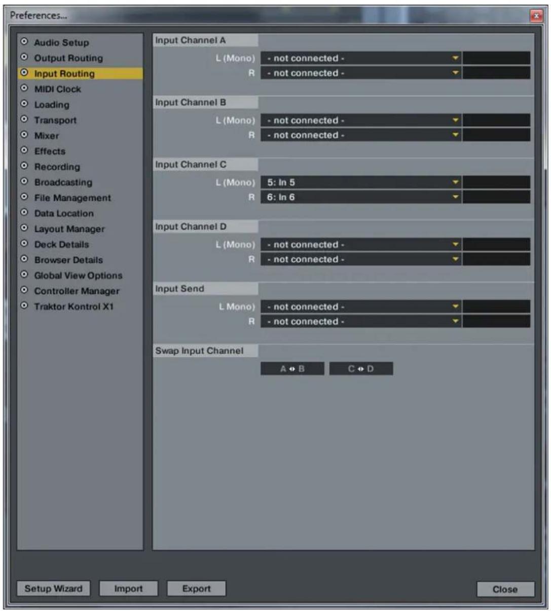
In order to make the signal become audible via master, the deck has to be switched to Audio Thru.
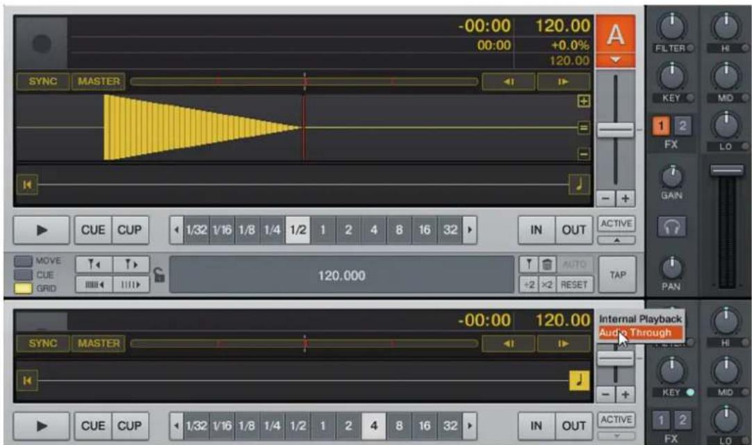
By using this routing option the mic signal can be enhanced with Traktor's internal effects.
Thru = The mic's signal is directly routed to the master output. With this variant a signal in the software is not necessary, thus becoming especially adequate for Traktor LE users or when using four decks in Traktor Pro.
Off = The mic becomes mute.
4.2.2 INPUTS
Inputs 1 and 2 can be routed to the software (SW) or Master Output (Mix) via the Routing Switches -F49- and -F50-. The Off position will turn off the inputs.
Example routing for IN1:
$$ \mathrm {I N} 1 = \mathrm {S W} $$
The signal of Input 1 will now be routed to the Input Channels 1 and 2. For this purpose Traktor Pro has to be configured correctly.:
First the correct inputs for the corresponding deck have to be selected. In this example deck C is used as analog channel.
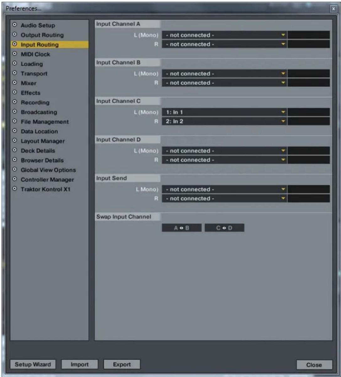
In order to make the signal become audible via Master, the deck has to be switched to Audio Thru.
In order to operate the signal via the mixer the Deck Select Switch has to be put to C. By using this routing option the input signal can be enhanced with the internal Traktor effects.
IN1 = Mix
If the Input Routing is switched to MIX, the input signal will be routed directly to the mixer. If the Deck Select Switch -30- is switched to IN1 both decks A and C in Traktor are mute. Only the analog signal is audible.
IN1 = Off
IN1 is switched to mute.
4.3 ANALOG MIXING FUNCTION
The Jockey 3 can also be used as 2 channel mixing console without the necessity to involve a computer. To do so both Deck Select Switches -T30- have to be switched to IN1 and IN2 respectively. Both Routing Switches -F49- and -F50- have to be switched to MIX.
Depending on which sources are connected to the Jockey 3-B66-, -B67-, it is possible to switch each deck to phono (turntables) or line (CD-players) -B65-.
Via the Cue Buttons -T35- it is possible to monitor the signal on each side. Via the Cue Mix Fader -T40- it is possible to simulate a mix through your headphones.
4.4 OUTPUTS
The jockey 3 disposes of three stereo output channels on the device's rear side.
Master 1-B63- as RCA output as well as Master 2-B62- as symmetrical 6.3mm jack output are adjusted via the Master Volume Encoder -T37-.
The Booth Output -B64- as RCA output is adjusted via the Booth Dial -T38-.
4.5 MASTER THRU AND CUE MASTER THRU
The Master Thru function is especially convenient for setups with 2 DJs. The second DJ's output signal is emitted via the 3.5mm jack -B61- through the Jockey 3 to master. If you wish to monitor the signal at the Jockey 3, the monitoring function can be activated with the Cue Master Thru Switch -F53-.
5. DEVICE SETTINGS & TESTS
A few adjustments and tests can be carried out with the Jockey 3 directly, without the need for a computer. In the following a few items are explained in detail.
5.1 MENU FOR MIDI CHANNEL ASSIGNMENT AND JOG WHEEL RESOLUTION ADJUSTMENTS
In order to access the setup menu proceed as follows:
- Make sure that the Jockey 3 is turned off (see position On/Off Button -B56-).
- Press and hold the Shift Button -T23- and turn on the Jockey 3 via the On/Off Button -B56-.
- Now release the Shift Button -T23-.
Now you have the possibility to adjust the MIDI channel assignment and the jog wheel resolution.
5.1.1 MIDI CHANNEL ASSIGNMENT

NOTE!
By default the Jockey 3 is configured for MIDI channels 1-4. Deck A is assigned to channel 1, Deck B is assigned to channel 2, Deck C is assigned to channel 3 and Deck D is assigned to channel 4. Reloop's official mappings are laid out for the standard configuration. An adjustment is usually not necessary.
However, if you wish to switch the decks to the MIDI channel combinations 5-8, 9-12 or 13-16, please proceed as follows:
- By pressing the left FX Dry/Wet Encoder you will access the MIDI channel assignment menu.
- Via the CUE Pads 1-4 -T20- it is now possible to adjust the MIDI channels. The corresponding Cue Pad is illuminated while the other Cue Pads are blinking.
| MIDI Channel Combination CUE Pad Button | |
| 1 - 4 1 | |
| 5 - 8 2 | |
| 9 - 12 3 | |
| 13 - 16 4 |
- When the desired MIDI channels have been selected, it is possible to store these permanently by pressing the Shift Button -T23-.
5.1.2 JOG WHEEL RESOLUTION
If Traktor Pro is being used, an adjustment of the jog wheel resolution is not necessary. However, not every software supports the high resolution of the Jockey 3's jog wheel -T22-. If you wish to adjust the resolution please proceed as follows:
- By pressing the FX Parameter 1 Encoder -T3- you will access the jog wheel resolution menu.
| Jog-Wheel-Resolution CUE-Pad-Button | |
| 512 1 | |
| 1024 2 | |
| 2048 | 3 |
| 4096 | 4 |
- Via the CUE Pads 1-4 -T20- the jog wheel resolution can be adjusted. The corresponding CUE Pad is illuminated while the remaining CUE Pads flash.
- When the desired resolution has been selected, it is possible to store it permanently by pressing the Shift Button -T23-.
5.2 LED FUNCTION TEST
Herewith you can check whether all LEDs that have been integrated in the Jockey 3 are working correctly. For the function test proceed as follows:
- Make sure that the Jockey 3 is turned off (see position On/Off Button -B56-).
- Press and hold the left Sync Button -T24- and turn on the Jockey 3 via the On/Off Button -B56-.
- Now release the Sync Button -T24-.
- Now all LEDs should be lit.
- In order to complete the test simply turn off the device via the On/Off Button -B56-.
5.3 AUTO SETUP
Herewith it is possible to carry out an auto setup. The auto setup is used to solve problems and should be carried out in case the Jockey 3 does not work correctly.
- Make sure that the Jockey 3 is turned off (see position On/Off Button -B56-).
- Press and hold the right Play Button -T27- and turn on the Jockey 3 via the On/Off Button -B56-.
- Now release the Play Button -T27-.
- The auto setup will now be carried out.
- In order to complete the auto setup press the right Play Button once again -T27-.
5.4 FIRMWARE VERSION CHECK
In order to verify your current Jockey 3 firmware version proceed as follows:
- Make sure that the Jockey 3 is turned off (see position On/Off Button -B56-).
- Press and hold the right Shift Button -T23- and turn on the Jockey 3 via the On/Off Button -B56-.
- The LEDs of the left FX Parameter 3 Encoder will now be illuminated. The number of illuminated LEDs corresponds to the currently installed firmware version.
- In order to stop this display release the Shift Button -T23- and reboot the device.
5.5 JOG DRAG
The Jockey 3 offers the possibility to adjust the jog wheel's drag for each jog wheel, according to one's desires. In order to adjust the jog wheel's drag turn the respective Jog Drag -S69- to the desired position.
5.6 JOG SENSITIVITY
Via the dial -B58- the jog wheel sensitivity can be adjusted.
5.7 LED DIMMER
Via the dial -B59- the LED background illumination for all LEDs can be adjusted.
6. UPDATES & SUPPORT
6.1 FIRMWARE UPDATE
For the Reloop Jockey 3 it is possible to update its firmware. Consequently it is possible to carry out adjustments as well as add new features. An instruction regarding this issue can be found online under the below mentioned address.
How to carry out a firmware update
- Make sure that the Jockey 3 is turned off (see position On/Off Button -B56-) and connected via USB to your computer.
- Press and hold the right CUP Button -T25- and the right CUE Button -T26- and simultaneously turn on the Jockey 3 via the On/Off Button -B56-.
- Now release both buttons.
- Now the upper LEDs of the UV meter blink. The Jockey 3 is now in update mode.
- Start the firmware update tool from the installation CD and open the firmware file that corresponds to your computer.
- Carry out the firmware update by clicking the "Start" button.
- The new firmware will be uploaded to the device.
- After the successful update exit the firmware update tool and reboot your Jockey 3 via the On/ Off Button -B56-.
6.2 DRIVER UPDATE
Updated drivers for the integrated audio interface that can be downloaded are also offered.
6.3 MAPPINGS
Follow-up versions for Traktor Pro and other DJ softwares
Updated mappings for follow-up versions of Traktor Pro and other DJ softwares are also always provided, so that the Jockey 3 can also be utilized in the future. For differing setups it is also possible to download special mappings that, in part, derive from the user community. Therefore regularly check the following website:
www.reloopdj.com/forum
Besides numerous downloads you can also find a support here.
7. APPENDIX
7.1 SYSTEM REQUIREMENTS TRAKTOR LE
PC:
- Windows XP (latest Service Pack, 32 bit), Windows Vista/Windows 7 (latest Service Pack, 32/64 bit)
Intel Pentium 4 2.4 GHz or Intel Core Duo
-2GBRAM
Mac:
- Mac OS X 10.5 or 10.6 (latest update)
Intel Core Duo
-2GBRAM
7.2 MIDI ASSIGNMENT CHART
MIDI MAP (Hex)
| SW name Type M | IDI MIDI 2 (Shift) | Remarks | ||
| TRAX SW/ENC 3 | 4/34 73/73 | |||
| FX SEL.(Adv.) SW | /W/ENC 19/19 | 58/58 | ||
| FX SEL.1(Cha.) | SW/ENC 1A/1A | 59/59 | ||
| FX SEL.2(Cha.) | SW/ENC 1B/1B | 5A/5A | ||
| FX SEL.3(Cha.) | SW/ENC 1C/1C | 5B/5B | ||
| LENGTH | SW/ENC 20/20 | 5F/5F | ||
| MOVE | SW/ENC 21/21 | 60/60 | ||
| JOG | SW/ENC 22/22 | 61/61 | ||
| JOG CW | SW | 23 | 62 | SCRATCH LED = ON & No Touch Inner Wheel |
| SW name Type | MIDI | MIDI 2 (Shift) | Remarks | ||
| JOG CCW SW 24 | 63 SCRATCH LED | ON & No Touch Inner Wheel | |||
| KEY PITCHBEND | /VR PitchBend 2C | ||||
| GAIN VR 2D 6C | |||||
| HIGH VR 2E 6D | |||||
| MID | VR 2F 6E | ||||
| LOW | VR 30 | 6F | |||
| CH FADER | VR 31 | 70 | |||
| FILTER | VR/CENTER | 32/32 | 71/71 | ||
| PAN VR/CENTER | 33/33 | 72/72 | |||
| CUE/MASTER FADER | VR 36 | -- | CH1 Only | ||
| CROSSFAVER VR | 37 | -- | CH1 Only | ||
| FX ON | SW/LED | 01/01 | 40/01 | ||
| RST | SW/LED | 02/02 | 41/02 | ||
| FX B1 | SW/LED | 03/03 | 42/03 | ||
| FX B2 | SW/LED | 04/04 | 43/04 | ||
| LOOP | SW/LED | 05/05 | 44/05 | ||
| RELOOP | SW/LED | 06/06 | 45/06 | ||
| < BEAT | SW/LED | 07/07 | 46/07 | ||
| BEAT > | SW/LED | 08/08 | 47/08 | ||
| DEL. | SW/LED | 09/09 | 48/09 | ||
| 5-8 | SW/LED | 0A/0A | 49/0A | ||
| 1/5 | SW/LED | OB/0B | 4A/0B | ||
| 2/6 | SW/LED | OC/0C | 4B/0C | ||
| 3/7 | SW/LED | OD/OD | 4C/OD | ||
| 4/8 | SW/LED | OE/OE | 4D/OE | ||
| XF A | SW/LED | OF/OF | 4E/OF | ||
| XF B | SW/LED | 10/10 | 4F/10 | ||
| XF C | SW/LED | 11/11 50/11 | |||
| XF D | SW/LED | 12/12 | 51/12 | ||
| TAP | SW/LED | 13/13 | 52/13 | ||
| |< CUE | SW/LED | 14/14 | 53/14 | ||
| CUE > | SW/LED | 15/15 | 54/15 | ||
| KEYLOCK | SW/LED | 16/16 | 55/16 | ||
| LOAD | SW/LED | 17/17 | 56/17 | ||
| PREV | SW/LED | 18/18 | 57/18 | ||
| SHIFT | SW 1D | -- | |||
| PITCH BEND - SW | 1E | 5D | |||
| PITCH BEND + | SW 1F | 5E | |||
| FX SEL.(Adv.) | LED | 19 | 0~7F(0~127) *1 | ||
| FX SEL.1(Cha.) | LED | 1A | 0~7F(0~127) *1 | ||
| FX SEL.2(Cha.) | LED | 1B | 0~7F(0~127) *1 | ||
| FX SEL.3(Cha.) | LED | 1C | 0~7F(0~127) *1 | ||
| CH Level meter | LEVEL | 1D | 0~A(0~10) | ||
CC-ABSOLUTE (VR)
Control Change messages are sent with status 0xBn , where n is the channel, for the specified CC controller. Thus the controller MIDI ID is indicated with the channel along with the CC number. The value from 0x00 to 0x7F, directly related to the location of the controller.
CC-RELATIVE (ENC)
Control Change messages are status OxBn, where n is the channel, for the specified CC controller. Thus the controller MIDI ID is indicated with the channel along with the CC number. The value from 0x40 to indicate the change in the controller. This is an offset to 0x40 "one's complement" notation. A message with data 0x43 indicates a positive change of 3. A messages with data 0x31 indicates a negative change of 15.
SWITCH ON/OFF (SW,CENTER,CW,CCW)
These messages are used for switches.
Control Change messages are sent with status 0x9n , SWITCH On and Off value are 0x7F and 0x00 where n is the channel.
LED ON/OFF (LED)
These messages are used for LED.
Control Change messages are sent with status 0x9n , LED On and Off value are 0x7F and 0x00 where n is the channel.
PITCHBEND
Pitchbend messages are status OxEn, where n is the channel, for the specified controller.
Thus the controller ID is indicated only by the channel.
For accurate changes, the 14 bit data in a pitch bend message is reserved for absolute controllers which require more than 7 bits of data.
LEVELLED (LEVEL)
These messages are used for LEVEL.
Control Change messages are sent with status 0x9n LED Off value is 0x00 and On value is related to LED amount, 0x01 with one LED, 0x02 with two LED..., where n is the channel.
7.3 TROUBLESHOOTING
If any problem should arise while using Reloop Jockey 3 the following chart is the first drop-in center:
| Symptoms Possible Causes | Corrective Measures | |
| The device does not receive any power when turning it on via the ON/OFF Button -B56-. | USB cord or mains adapter are not connected correctly. | Check whether the USB cord is con- nected correctly to a free USB port of your computer and Jockey 3's USB port-B69-. Please also check whether the mains adapter is connected correctly to the mains connection -B54-. |
| The Controller's LEDs are only weakly lit and the device does not react. | The power supply is not sufficient. | Connect your computer to a secured power line. Also it is necessary to con- nect the included mains adapter to the corresponding jack -B54-. |
| Not all outputs of the integrated audio interface can be selected in the DJ software. | The ASIO driver is not installed correctly. | Please install the ASIO driver again. Also please read the paragraph „ASIO Driver Installation" in the chapter „Computer Configuration". |
| The audio interface's sound is distorted. | The ASIO driver is not used.The performance set- tings of your computer do not correspond to the computer's capacity. | Please make sure that the ASIO driver is installed and is also being used. Ple- ase refer to the paragraph „ASIO Driver Installation" in the chapter „Computer Configuration".It is also possible that in the ASIO driver's settings the available compu- ter capacity has to be re-configured.Open the settings in Traktor, select the category „Audio Setup" and click on the „Settings" button next to the sound card selection window. Then select „System Performance" ➔ „Normal".If the problems persist you can also select „Relaxed" in the same menu. |
| The DJ software does not show any reaction to the usage of any of the controller's control elements. | Traktor LE is not configu- red correctly.Traktor Pro is not ins- talled correctly. | If you use the included Traktor LE versi- on, start the Setup Wizard again. Refer to the paragraph „Traktor LE Setup" in the chapter „Computer Configuration".When using Traktor Pro the mapping has to be loaded again. To do so follow the instructions in the paragraph „Trak- tor Pro Configuration" in the chapter „Computer Configuration". |
| The decks do not react to the control elements of the controller. | The Deck Select Swit- ches are in the IN1/IN2 position. | Make sure that the Deck Select Swit- ches are switched to the Traktor decks. |
| In analog mode the inputs are not played via the master output. | The two Input Switches are not in the MIX posi- tion. | Put both Input Switches to MIX positi- on. |
| There is a problem that is not listed here. | Various causes. Visit the w | Website www.reloopdj.com/ forum in order to get support regarding your Reloop products. |
7.4 TECHNICAL SPECIFICATIONS
The following specifications are not verified by Global Distribution GmbH in terms of plausibility and accuracy:
1. General Section
Power Source: USB 5V 500mA / DC: 6V, 2A;
Dimensions: 420 x 315 x 61.55 mm
Weight: 5 kg
USB
- USB Slave Player Sektion: (Signal Format: MP3, 128kbps, Sony Sound Forge 8.0)
2.1 Output Level: (Sony Sound Audio Dev ice Type: Jockey 3 ME)
Master OUT: -9 dBV +/-2dB (TCD782 TRK16)
Phones OUT: -10dBV +/-2dB (TCD782 TRK16)
2.2 Frequency Response: (Sony Sound Audio Device Type: Windows classic Wave Driver)
Master OUT: 17-16 kHz +/-1,5dB (TCD782 TRK1, 4, 16)
2.3 THD+N: (Sony Sound Audio Device Type: Windows classic Wave Driver)
Master OUT: .0.01% (TCD782 TRK2, Master VR OUT: 0dB)
Master OUT: .0.01% (96K-TDC782 TRK2, Master VR OUT: 0dB)
2.4 S/N Ratio: (Sony Sound Audio Device Type: Windows classic Wave Driver)
Master OUT: 95dB (TCD782 TRK2, 8; Master VR OUT: 0dB)
2.5 LR Trennung: (Sony Sound Audio Device Type: Windows classic Wave Driver)
Master OUT: 85dB (TCD782 TRT9, 11)
3 Recording und Playback (Line 1Khz, OdDV, MIC 1KHz -36dB Input, 44.1K Sample Rate 24bit)
3.1 Output+3dBV (1.41V) +/- 1.5dB
THD+N. < 0.02% (w/20KHz LPF, A-weighted)
THD+N. < 0.02% (w/20KHz LPF, A-weighted 96K Sample Rate 24bit)
3.2 S/N Ratio+3dBV (1.41V) +/- 1.5dB
Line: 82dB
Mic: >70dB
Crosstalk: > 75dB between L and R channel
ENGLISH
MODE D'EMPLOI
ACHTUNG!

6.Mises a jours & assistance. 81
Mode Internal Mixing
| Device In-Port Out-Port | ||
| Jockey 3 V* (Deck A) Reloop Jockey 3 | ||
| Jockey 3 V* (Deck B) Reloop Jockey 3 | ||
| Jockey 3 V* (Deck C) Reloop Jockey 3 | ||
| Jockey 3 V* (Deck D) Reloop Jockey 3 | ||
| Jockey 3 V* (Mixer) Reloop Jockey 3 | ||
| Jockey 3 V* (FX Presets) Reloop Jockey 3 |
4. UTILISATION
Control Change messages are sent with status OxBn, where n is the channel, for the specified CC controller. Thus the controller MIDI ID is indicated with the channel along with the CC number. The value from 0x00 to 0x7F, directly related to the location of the controller.
CC-RELATIVE (ENC)
Control Change messages are status OxBn, where n is the channel, for the specified CC controller. Thus the controller MIDI ID is indicated with the channel along with the CC number. The value from Ox40 to indicate the change in the controller. This is an offset to Ox40 "one's complement" notation. A message with data Ox43 indicates a positive change of 3. A messages with data Ox31 indicates a negative change of 15.
SWITCH ON/OFF (SW,CENTER,CW,CCW)
These messages are used for switches.
Control Change messages are sent with status 0x9n , SWITCH On and Off value are 0x7F and 0x00 where n is the channel.
LED ON/OFF (LED)
These messages are used for LED.
Control Change messages are sent with status 0x9n LED On and Off value are 0x7F and 0x00, where n is the channel.
PITCHBEND
Pitchbend messages are status OxEn, where n is the channel, for the specified controller.
Thus the controller ID is indicated only by the channel.
For accurate changes, the 14 bit data in a pitch bend message is reserved for absolute controllers which require more than 7 bits of data.
LEVELLED (LEVEL)
These messages are used for LEVEL.
Control Change messages are sent with status 0x9n LED Off value is 0x00 and On value is related to LED amount, 0x01 with one LED, 0x02 with two LED..., where n is the channel.
| Symptoms Possible Causes | Corrective Measures | |
| The device does not receive any power when turning it on via the ON/OFF Button -B56-. | USB cord or mains adapter are not correctly connected. | Check whether the USB cord is correctly connected to a free USB port of your computer and Jockey 3's USB port -B69-. Please also check whether the mains adapter is connected correctly to the mains connection -B54-. |
| The Controller's LEDs are only weakly lit and the device does not react. | The power supply is not sufficient. | Connect your computer to a secured power line. Also it is necessary to connect the included mains adapter to the corresponding jack -B54-. |
| Not all outputs of the integrated audio interface can be selected in the DJ software. | The ASIO driver is not installed correctly. | Please install the ASIO driver again. Also please read the paragraph „ASIO Driver Installation" in the chapter „Computer Configuration". |
| The audio interface's sound is distorted. | The ASIO driver is not used.The performance settings of your computer do not correspond to the computer's capacity. | Please make sure that the ASIO driver is installed and is also being used. Please refer to the paragraph „ASIO Driver Installation" in the chapter „Computer Configuration".It is also possible that in the ASIO driver's settings the available computer capacity has to be re-configured. Open the settings in Traktor, select the category „Audio Setup" and click on the „Settings" button next to the sound card selection window. Then select „System Performance" > „Normal". If the problems persist you can also select „Relaxed" in the same menu. |
| The DJ software does not show any reaction to the usage of any of the controller's control elements. | Traktor LE is not configured correctly.Traktor Pro is not installed correctly. | If use the included Traktor LE version, start the Setup Wizard again. Refer to the paragraph „Traktor LE Setup" in the chapter „Computer Configuration".When using Traktor Pro the mapping has to be loaded again. To do so follow the instructions in the paragraph „Trakto Pro Configuration" in the chapter „Computer Configuration". |
| The decks do not react to the control elements of the controller. | The Deck Select Switches are in the IN1/IN2 position. | Make sure that the Deck Select Switches are switched to the Traktor decks. |
| In analog mode the inputs are not played via the master output. | The two Input Switches are not in the MIX position. | Put both Input Switches to MIX position. |
| There is a problem that is not listed here. | Various causes. Visit the website www.reloopdj.com/forum in order to get support regarding your Reloop products. | |
7.4 CARACTERISTIQUES
2.1 Output Level: (Sony Sound Audio Dev Ice Type: Jockey 3 ME)
Master OUT: -9 dBV +/-2dB (TCD782 TRK16)
Phones OUT: -10dBV +/-2dB (TCD782 TRK16)
- Section USB Slave Player: (Signal Format: MP3, 128kbps, Sony Sound Forge 8.0)
Master OUT: 17-16 kHz +/-1,5dB (TCD782 TRK1, 4, 16)
2.3 THD+N: (Sony Sound Audio Device Type: Windows classic Wave Driver)
Master OUT: < 0,01% (TCD782 TRK2, Master VR OUT: OdB)
Master OUT: .01% (96K-TDC782 TRK2, Master VR OUT: 0dB)
2.4 S/N Ratio: (Sony Sound Audio Device Type: Windows classic Wave Driver)
Master OUT: 95dB (TCD782 TRK2, 8; Master VR OUT: OdB)
2.5 LR Trennung: (Sony Sound Audio Device Type: Windows classic Wave Driver)
Master OUT: 85dB (TCD782 TRT9, 11)
3 Recording et Playback (Line 1Khz, OdDV, MIC 1KHz -36dB Input, 44.1K Sample Rate 24bit)
3.1 Output+3dBV (1.41V) +/- 1.5dB
THD+N. .02% (w/20KHz LPF, A-weighted)
THD+N. < 0,02% (w/20KHz LPF, A-weighted 96K Sample Rate 24bit)
3.2 S/N Ratio+3dBV (1.41V) +/- 1.5dB
Line: 82dB
Mic: >70dB
Crosstalk: 75dB entre canal L et R

WWW.RELOOPDJ.COM
Reloop Trademark
Global Distribution GmbH
Schuckertstr. 28
48153 Muenster / Germany
Copyright 2009
Nachdruck Verboten!