IQ2+USB - Mixer Reloop - Free user manual and instructions
Find the device manual for free IQ2+USB Reloop in PDF.

| Product Type | Professional 2-channel mixer with DSP effects and USB interface |
| Brand | Reloop |
| Model | IQ2+ USB |
| Dimensions (W x D x H) | 250 x 355 x 104,9 mm |
| Weight | 4,2 kg |
| Power Supply | Mains 240 V, 50 Hz |
| Inputs | 2 x Phono (2 mV/47 kΩ), 2 (+2) x Line (200 mV/47 kΩ), 1 x Mic (2 mV/10 kΩ), 1 x AUX (200 mV/10 kΩ) |
| Outputs | 1 x Master (1 V/1 kΩ), 1 x Send (316 mV/2,2 kΩ), 1 x Rec (316 mV/2,4 kΩ), 2 x headphone (1 V/33 Ω) |
| Frequency Response | 25 Hz - 20 kHz ± 2 dB |
| Signal-to-noise ratio (Line, CD, AUX) | > 80 dB |
| Equalizer | 3-band (bass, mid, treble) for channels A+B; 2-band for microphone |
| Built-in DSP effects | 8 effects (Echo, Auto Pan, Flanger, Manual Filter, Auto Filter, Reverb, Transformer, Pitch Shifter) |
| Crossfader effects | LoopX, PitchX, StutterX |
| USB Connection | 2 USB ports (channel A and B) for computer connection, Plug & Play |
| Additional Functions | Talkover microphone, Cue pre-listening, automatic and manual BPM counter, fader start for compatible CD players |
| Maintenance and cleaning | Use a slightly damp cloth; avoid solvents, aerosols and greasy products |
| Safety | Do not open the housing, avoid humidity, unplug before cleaning, use in accordance with CE guidelines |
| Spare parts and repairability | Externally replaceable wear parts; maintenance by qualified personnel; fuses of same type only |
| General Information | Console compatible with Reloop CD players with fader start; USB interface for external sound card |
Frequently Asked Questions - IQ2+USB Reloop
User questions about IQ2+USB Reloop
0 question about this device. Answer the ones you know or ask your own.
Ask a new question about this device
Download the instructions for your Mixer in PDF format for free! Find your manual IQ2+USB - Reloop and take your electronic device back in hand. On this page are published all the documents necessary for the use of your device. IQ2+USB by Reloop.
USER MANUAL IQ2+USB Reloop
For your own safety, please read this operation manual carefully before initial operation! All persons involved in the installation, setting-up, operation, maintenance and service of this device must be appropriately qualified and observe this operation manual in detail. This product complies with the requirements of the applicable European and national regulations. Conformity has been proven. The respective statements and documents are deposited at the manufacturer.
Mode d'emploi
m ATTENTION!
2 channel DSP / USB effect mixer
To prevent fire or avoid an electric shock do not expose the device to water or fluids. Never open the housing!
ATTENTION!
Congratulations on purchasing your Reloop IQ2+ / Reloop IQ2+ USB. Thank you for placing your trust in our disc jockey technology. Before operating this equipment we ask you to carefully study and observe all instructions.
Please remove the Reloop IQ2+ / Reloop IQ2+ USB from its packaging. Check before initial operation to make sure that the device has not been visibly damaged during transport. If you detect any damage to the power cable or the casing, do not operate the device. Contact your specialised dealer.
SAFETY INSTRUCTIONS

CAUTION!
Please exercise particular caution when handling 240 V power voltage. This voltage rating may lead to a critical electrical shock! Any damage caused by the non-observance of this operation manual excludes any warranty claims. The manufacturer is not liable for any damage to property or for personal injury caused by improper handling or non-observance of the safety instructions.
- This device left the factory in perfect condition. To maintain this condition and to ensure a risk-free operation the user must observe the safety instructions and warnings contained in this operation manual.
- For reasons of safety and certification (CE) the unauthorised conversion and/or modification of the device is prohibited. Please note that in the event of damage caused by manual modification to this device any warranty claims are excluded.
- The inside of the device does not contain any parts which require maintenance, with the exception of wear parts that can be exchanged from the outside. Qualified staff must carry out maintenance, otherwise the warranty does not apply!
- The Fuse must exclusively be exchanged against fuses of the same class, with the same trigger features and nominal current rating.
- Ensure that the power will only be supplied after the device has been fully set up. Always plug in the mains plug last. Ensure that the mains switch is in the "OFF" position when connecting the device to power.
- Only use cables that comply with regulations. Observe that all jacks and bushes are tightened and correctly hooked up. Refer to your dealer if you have any questions.
- Ensure that when setting up the product the mains cable is not squashed or damaged by sharp edges.
- Prevent the mains cable from coming into contact with other cables! Exercise great care when handling mains cables and connections. Never touch these parts with wet hands!
- Connect the power cable exclusively to appropriate shock-proof outlets. The only supply point to be used is a supply outlet in accordance with specifications of the public supply network.
- Disconnect the device from the supply outlet when not in use and before cleaning! Be sure to hold the mains plug by the body. Never pull the mains cord!
- Position the device on a horizontal and stable low-flame base.
- Avoid any concussions or violent impact when installing or operating the device.
-
When selecting the location of installation make sure that the device is not exposed to excessive heat, humidity, and dust. Be sure that no cables lie around openly. You will endanger your own safety and that of others!
-
Do not rest any containers filled with liquid that could easily spill onto the device or in its immediate vicinity. If, however, fluids should access the inside of the device, immediately disconnect the mains plug. Have the device checked by a qualified service technician before re-use. Damage caused by fluids inside the device is excluded from the warranty.
- Do not operate the device under extremely hot (in excess of 35^ C) or extremely cold (below 5^ C) conditions. Keep the device away from direct exposure to the sun and heat sources such as radiators, ovens, etc. (even during transport in a closed vehicle). Never cover the cooling fan or vents. Always ensure sufficient ventilation.
- The device must not be operated after being taken from a cold environment into a warm environment. The condensation caused hereby may destroy your device. Do not switch on or operate the device until it has reached ambient temperature!
- Controls and switches should never be treated with spray-on cleaning agents and lubricants. This device should only be cleaned with a damp cloth. Never use solvents or cleaning fluids with a petroleum base for cleaning.
- When relocating, the device should be transported in its original packaging.
- When starting operation, the crossfaders and volume controls of your amplifier must be set to minimum level. Bring the loudspeaker switches into the "OFF" position. Wait between 8 to 10 seconds before increasing the volume to avoid shot noise created by transient effect, which could cause damage to loudspeakers and the diplexer.
Devices supplied by voltage should not be left in the hands of children. Please exercise particular care when in the presence of children. - At commercial facilities the regulations for the prevention of accidents as stipulated by the organization of professional associations must be observed.
- At schools, training facilities, hobby and self-help workshops the operation of the device must be monitored with responsibility by trained staff.
- Keep this operation manual in a safe place for later reference in the event of questions or problems.
APPLICATION IN ACCORDANCE WITH REGULATIONS
- This device is a professional mixing console which can regulate and mix low level audio signals. The device is thereby connected between a signal source and an audio amplifier.
- This product is authorised for connection to 240 V, 50 Hz AC and is designed exclusively for indoor application.
- If the device is used for any other purposes than those described in the operation manual, damage can be caused to the product, leading to exclusion of warranty rights. Moreover, any other application that does not comply with the specified purpose harbours risks such as short circuit, fire, electrical shock, etc.
- The serial number determined by the manufacturer must never be removed, otherwise all warranty rights will expire.
MAINTENANCE
- Check the technical safety of the device regularly for damage to the mains line or the casing, as well as for wearout of wear parts such as rotary and sliding switches.
- If it is to be assumed that safe operation is no longer feasible then the device must be disconnected and secured against accidental use. Always disconnect the mains plug from the outlet!
- It must be assumed that a safe operation is no longer feasible if the device bears visible defects, if the device no longer functions, following longer storage under unfavourable conditions or after major transport stress.
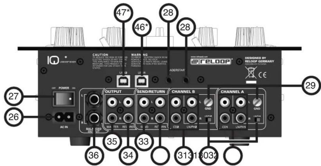
REAR PANEL
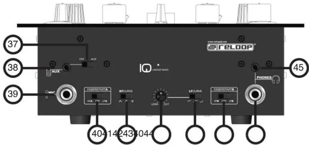
FRONTSIDE
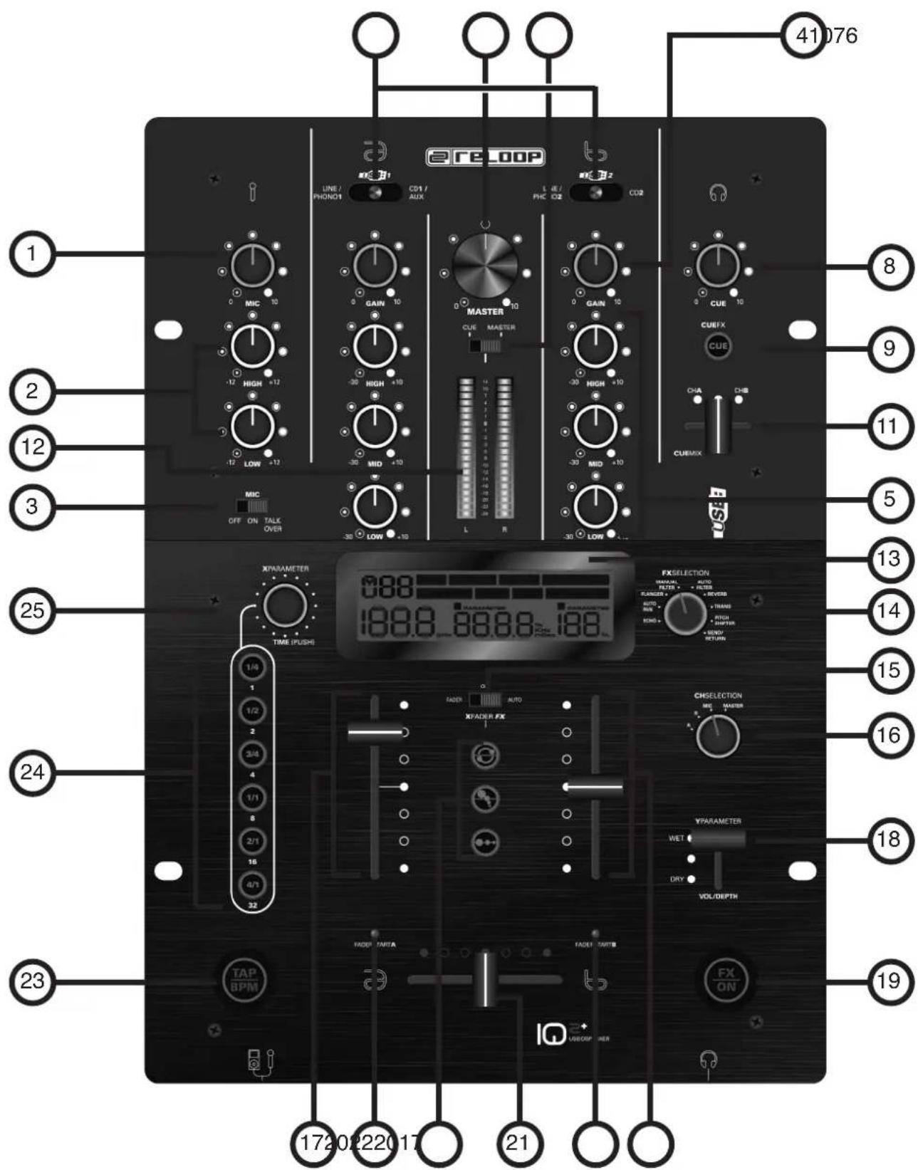
DESIGNATIONS
- ......Microphone volume knob
- 2-band equalizer for microphone
- ......Microphone, talkover, activation switch
- Gain knob for channels A + B
- 3-band equalizer for channels A + B
- Signal input selector for channels A + B (USB position only available for Reloop IQ2+ USB)
- Master volume knob
- ...Cue volume knob
- .........CueFX LED button
- .........Cue/Master switch
- .........CueMix fader
- Modulation LEDs for cue/master
- LCD info display
- ....Effect-selection knob
- .........Crossfader-effect switch
- ....Effect assignment knob
17.......Linefaders for channels A + B - ...Y parameter effect fader
- .FX button ON/OFF
- .........Crossfader-effect assignment LEDs
- .........Crossfader
- .........Crossfader effect buttons a, b, c
- ......TAP/BPM button
- ....Beat assignment buttons for DSP effect unit
- ...X parameter knob
- ....Input for mains cord
- ON/OFF switch
28.......Input for fader start function - .........GND grounding screws
- Phono/line switch for channels A + B
- Input for channels A + B (RCA)
- ....Input for return signal (RCA)
- Output for send signal (RCA)
- ......REC output (RCA)
- .........Master output (RCA)
- .........Master output symmetrical (6.3 mm jack)
- CD1/AUX input switch
- ......AUX input (3.5 mm jack)
- ......Microphone input (6.3 mm jack)
- .........Faderstart switch for channels A + B
- .........Crossfader curve switch
42....Linefader curve knob - ....Linefader curve switch
- ......Headphones input 1 (6.3 mm jack)
- ......Headphones input 2 (3.5 mm jack)
- .........USB port 1 (only available for Reloop IQ2+ USB)
- .........USB port 2 (only available for Reloop IQ2+ USB)
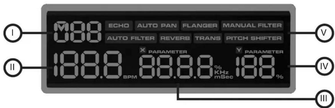
I.........Channel assignment indicator
II.....BPM indicator
III.....X parameter indicator
IV.....Y parameter indicator
V.........Effect selection indicator
CONNECTIONS
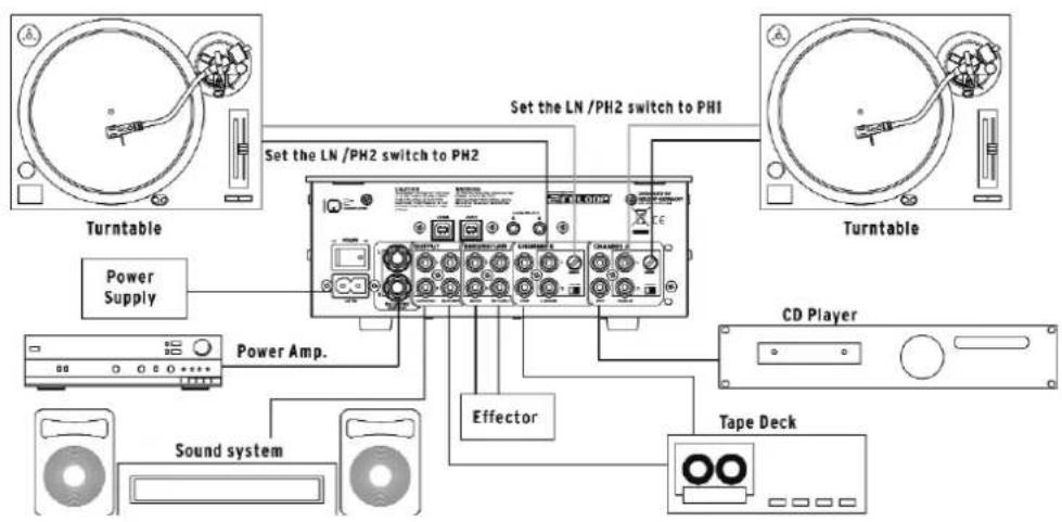
- Connect your line sources (CD players, MD players, etc.) and your turntables via the inputs for channels A + B -31-. If you wish to connect turntables to the phono inputs make sure to put the phono/line switch(es) -30- to the "PH" position; when connecting line sources to these inputs you have to put the phono/line switch(es) -30- to the "LN" position.
ATTENTION!
Please always make sure that the device is turned off when using the phono/line switches -30-.
- Connect the grounding cables of your turntables with the GND grounding screws of your mixer -29-.
- Connect your microphone to the microphone input -39-.
- Connect your headphones via the headphones input 1 -44- (6.3 mm jack). Alternatively or if required you can connect a second pair of headphones with the headphones input 2 -45- (3.5 mm jack).

- Connect an MP3 player (for example) to the AUX input (3.5 mm jack) -38-. If you want to play tracks from your MP3 player via the mixer, the CD1/AUX input switch -37- has to be in the "AUX" position. If you want to play tracks from the CD player connected to channel A via your mixer, the CD1/AUX input switch -37- has to be in the "CD1" position.
NOTE!
The function described above is only available for channel A.
- Connect the output for the send signal -33- to the input of your effect device and sampler respectively. Connect the output of your effect device and sampler respectively to the input for the return signal -32-.
- If required connect your CD player's fader start cords to the input for the fader start function -28-.

NOTE!
The input "A" for the fader start function -28- is assigned to channel A and the input "B" for the fader start function is assigned to channel "B".
- Connect your stereo system to the master output (RCA) -35- or to the symmetrical master output (6.3 mm jack) -36-.
- Connect a recording device of your choice to the REC output (RCA) -34-.
(only available for Reloop IQ2+ USB)
- Connect the USB port 1 -46- to your computer's USB port and connect the USB port 2 -47- to another USB port of your computer.

NOTE!
Please also follow your computer's instruction manual regarding this matter.
- Connect the mains cord to the input for the mains cord -26-. Connect the mains cord to an outlet.
OPERATION
- Power on [see designations; number 27]
After having connected all necessary devices turn on the mixer via the ON/OFF switch -27-.
- Signal input selection [see designations; numbers 6, 30, 37]
With the signal input selectors for channels A + B -6- you can choose between line, phono, CD, AUX and USB sources (only available for the Reloop IQ2+ USB); (for channel A you have the additional AUX position as described in the chapter "connections", number 5). Please follow the labeling of the signal input selector for channels A + B -6- and also the phono/line switch position for channels A + B -30-.
- Gain [see designations; numbers 1 & 4]
The input volume for channels A + B can be adjusted via the gain knobs for channels A + B -4-. With the microphone gain knob -1- you can adjust the input volume of your DJ microphone channel.
- Equalizer [see designations; numbers 2 & 5]
It is possible to adjust the low, mid and high frequencies via the 3-band equalizer for channels A + B -5-. With the 2-band equalizer for the microphone -2- you can adjust the low and high frequencies for the DJ microphone channel.
- Channels A + B [see designations; numbers 17 & 42]
Via the linefaders -17- you can adjust the output volume for channels A + B. The linefader curve can be adjusted via the linefader curve switch -43- and the linefader curve knob -42-. There are three different positions for the linefader curve switch. If the switch is in the outer left position you will be able to hear the signal with the linefader being in a fairly low position; the linefader is "hard" (highly appropriate for cutting and scratching). If the switch is in the middle position you will obtain a linear curve, this means the linefader is "smooth" (great for long running mixes); the signal rises proportionally to the linefader's position. When the switch is in the outer right position the linefader becomes "hard", similar to the left position. The signal only becomes audible when the linefader is in a rather high position (also highly appropriate for cutting and scratching).
Furthermore it is possible to obtain a vernier adjustment of the fader curve by using the linefader curve knob -42- in order to work even more precisely. By turning the knob clockwise the fader curve becomes "hard"; by turning the knob counter clockwise the fader curve becomes "smooth".
- Crossfader [see designations; numbers 21 & 41]
With the crossfader -21- you can switch between the left and right crossfader channel. The crossfader curve can be adjusted via the crossfader curve switch -41-. When the switch is in the left or middle position the crossfader curve becomes "hard" (highly appropriate for cutting and scratching); when the switch is in the right position the crossfader curve becomes "smooth" (highly appropriate for long running mixes).
- Fader start [see designations; numbers 17, 21, 28 & 40]
If you have connected two appropriate CD players to your Reloop IQ2+ (as described in chapter "connections", point 7) it is possible to operate them by remote control using the crossfader -21- or the linefaders -17-.
If you want to start the CD player for channel A via the crossfader the fader start switch for channel A -40- has to be in the "XFA" position; if you want to start the CD player via the linefader the fader start switch for channel A has to be in the "LFA" position. If you do not want to use the fader start function the fader start switch has to be in the "OFF" position.
If you want to start the CD player for channel B via the crossfader the fader start switch for channel B -40- has to be in the "XFA" position; if you want to start the CD player via the linefader the fader start switch for channel B has to be in the "LFA" position. If you do not want to use the fader start function the fader start switch has to be in the "OFF" position.
If you push the crossfader all the way to the left side, alternatively the left linefader all the way to the top, (depending on the fader start mode) the CD player connected to the input A for the fader start function -28- will switch to playback mode and the CD player connected to the input B for the fader start function -28- will return to the last saved cue point and switch to pause mode. If you push the crossfader all the way to the right, alternatively the right linefader all the way to the top position the CD player connected to the input B for the fader start function will switch to playback mode and the CD player connected to the input A for the fader start function will return to the last saved cue point and switch to pause mode, etc.
NOTE!
Concerning this matter please also pay attention to the information regarding fader start play of your CD player's instruction manual. Depending on the CD player model, variations of the functions described above are possible.
- DJ microphone [see designations; numbers 1, 2 & 3]
Via the microphone volume knob -1- it is possible to adjust the DJ mic channel's output level. Using the 2-band equalizer for the microphone -2- it is possible to adjust the DJ mic volume level's high and low frequencies.
If the microphone talkover activation switch -3- is in the "OFF" position the microphone channel is turned off. If the microphone talkover activation switch -3- is in the "ON" position the microphone channel is turned on.
If the microphone talkover activation switch -3- is in the "Talk Over" position a volume suppression of all remaining channels will be activated as long as you use the microphone. As soon as no signal is routed through the microphone the volume will return to its original level.
- Modulation [see designations; numbers 4, 5, 7, 10, 17 & 42]
The modulation LEDs for cue/master -12- indicate the volume level for channels A and B. Between the LEDs there is a bar featuring numbers from -24 to +14.
Adjust the channel's volume via linefader -17-, 3-band equalizer -5-, gain knobs -4- and master volume knob -7- in a way that the red LEDs rarely reach values above "0"; this way you avoid overmodulations.
Via the cue/master switch -10- it is possible to determine which signal the LEDs -12- should display. If the switch -10- is in the "cue" position the cue signal will be displayed via the LEDs. The cue signal for channel A will be displayed on the left LED bar, the cue signal for channel B will be displayed on the right LED bar. If the cue/master switch -10- is in the "master" position the master volume level is displayed on both LED bars.
- Monitoring [see designations; numbers 8, 9 & 11]
With the CueMix fader -11- you can determine which signal you would like to monitor. If the CueMix fader -11- is in the outer left position (position "CHA"), you will hear the cue signal for channel A via your headphones; if the CueMix fader -11- is in the outer right position (position "CHB"), you will hear the cue signal for channel B via your headphones. If the CueMix fader -11- is in the middle position you will be able to hear the cue signals for both channels via your headphones.
It is possible to adjust the cue signal's volume via the cue volume knob -8-. By pressing the CueFX LED button -9- it is possible to add the previously adjusted DSP effects (see chapter "operation"; number 14) to the cue signal. This way it is possible to exactly hear what the effect is going to sound like.
- Outputs [see designations; numbers 7, 17, 35 & 36]
By using the line faders -17- you can adjust the output volume of the master output -35 and 36 respectively-. With the master volume knob -7- the output volume level can be adjusted. Use this knob in order to prevent your stereo system from receiving an output signal that is too high.
NOTE!
The REC output -34- is not influenced by the master volume knob's -7-position.
- Effect send/return [see designations; numbers 13, 14 & 16]
If you have connected an external effects device, an external sampler or drumcomputer to the IQ2+ (as described in the chapter "connections", number 6) you can make the signal available by putting the effect selection knob -14- to the "send/return" position. By using the channel assignment knob -16- you can now determine which signal should be routed through the external device. On the upper left side of the LCD info display -13, I- you can see the designated signal.
NOTE!
You can choose between channels A and B ("CH1" and "CH2" respectively is shown on the LCD info display -13, I-), the mic channel ("MC" is shown on the display -3, I-) and the master signal ("MA" is shown on the display -3, I-).
- Beatcounter [see designations; numbers 13, 16 & 23]
The Reloop IQ2+ mixer is equipped with an automatic and manual beatcounter. When you turn on the mixer the automatic beatcounter is active. By using the effect assignment knob -16- you can choose the channel whose BPM value has to be determined (position A corresponds to channel A; position B corresponds to channel B). If a track is playing the mixer will automatically calculate the BPM (Beats Per Minute). The BPM value is shown on the LCD info display -13, II-; the number flashes while the beatcounter is still determining the track's speed or when there is no output signal or one that is to weak or can not be determined. In this case you can operate the beatcounter manually. In order to use the manual beatcounter please tap the TAP/BPM button -23- permanently to the beat of the bassdrum or to the beat of any other continuous rhythm element. If the manual beatcounter is active the TAP/BPM button -23- will flash. In order to return to the automatic beatcounter it is necessary to push and hold the TAP/BPM button -23- for approximately three seconds until the button stops flashing. The automatic beatcounter has now been reactivated.
NOTE!
Beats can not be determined by the IQ2+ if there is no continuous rhythm structure or if the beats do not stand out clearly enough from the rest of the track in order to be identified as rhythm element. Common time beats are ideal for the IQ2+.

NOTE!
Via the separate TAP/BPM button -23- you can manually adjust the bars when effects are active.
- DSP effects [see designations; numbers 13, 14, 15, 16, 18, 19, 24 & 25]
Besides the effect send/return loop and the beatcounter, the DSP effect unit features 8 different digital effects (see below for an exact description).
First of all choose the required effect via the effect selection knob -14- and determine the channel to which the effect has to be assigned to via the effect assignment knob -16-. The designated channel is shown on the upper left side of the LCD info display -13, I-. By using the X parameter knob -25- you can adjust the effect's value that will then be shown on the LCD info display -13, III-.
By using the Y parameter effect fader -18- you can adjust the designated effect's intensity. The effect's value percentage is shown on the lower right side of the LCD info display -13, IV-.
If the Y parameter effect fader is in the "Dry" position the effect will have an intensity of 0% ; this means the effect is not audible. If the y parameter effect fader -18- is in the "Wet" position the effect has an intensity of 100% .
The beat assignment buttons for the DSP effect unit -24- show which bar length corresponds to the designated time parameter. If the time parameter does not exactly correspond to the bar lengths the two bar buttons that are between this value will be illuminated (except the Pitch Shifter effect: In this case the time parameter does not correspond to the channel's bar length but to the overall speed).
By pushing the FX button -19- you can activate the effect unit (button is illuminated). By pushing the button again the DSP effects will be deactivated.

NOTE!
The DSP effect unit is only available for use if the crossfader effect unit is turned off. To obtain this the fader effect switch -15- must be in the "OFF" position.
Depending on the effect, the time parameter's type and interval and the adjustments according to the beat assignment buttons -24-, will differ.
- ECHO = echo effect
Continuously repeats a certain interval of the signal.
Time parameter value: 2 - 2000 msec
Direct bar assignment: Intervals adjustable from 125 - 2000
By turning the X parameter knob -25- the value will be changed in steps of 1. Push, hold and turn the X parameter knob -25- and the value will be changed in steps of 100.
Y parameter dry/wet value: 0 - 100%
- AUTO PAN = panorama effect
Produces the signal's continuous fading of the signal from the left to the right channel and back again.
Time parameter value: 30 - 65000 msec
Direct bar assignment: 500/1000/2000/4000/8000/16000 msec
By turning the X parameter knob -25- the value will be changed in steps of 1. Push, hold and turn the X parameter knob -25- and the value will be changed in steps of 100.
Y parameter dry/wet value: 0 - 100%
- FLANGER = flanger effect
Doubles the signal and shifts it by a marginal value.
Time parameter value: 100 - 65000 msec
Direct bar assignment: 500/1000/2000/4000/8000/16000
By turning the X parameter knob -25- the value will be changed in steps of 1. Push, hold and turn the X parameter knob -25- and the value will be changed in steps of 100.
Y parameter dry/wet value: 0 - 100%
- MANUAL FILTER = HiPass/LowPass filter effect
With this effect you can manually control a Hipass and LowPass filter effect respectively.
Time parameter value: LowPass 0.05 - 20.2 Hz / HiPass 0.13 - 21.1 Hz
Direct bar assignment: LowPass 0.45/2.27/7.13/18.4 Hz - HiPass 1.63/5.73 Hz
By turning the Xparameter knob -25- the value will be changed in steps from 0.2 - 0.4. Push, hold and turn the Xparameter button -25- and the value will be changed in steps of 0.1.
- AUTO FILTER = HiPass/LowPass filter effect
Filters high and low frequencies alternately according to the adjusted bar value.
Time parameter value: 100 - 65000 msec
Direct bar assignment: 500/1000/2000/4000/8000/16000 msec
By turning the X parameter knob -25- the value will be changed in steps of 10. Push, hold and turn the X parameter knob -25- and the value will be changed in steps of 100.
Y parameter dry/wet value: 0 - 100%
- REVERB = reverb effect
Simulates reflecting sound waves in a naturally restricted area.
Time parameter value: 0 - 100%
Direct bar assignment: 0/20/40/60/80/100%
By turning the X parameter knob -25 the value will be changed in steps of 1. Push, hold and turn the X parameter knob -25- and the value will change in steps of 10. Y parameter dry/wet value: 0 - 100%
- TRANS = transformer effect
Creates the signal's chopping by fading in and out, similar to fast cutting with the crossfader.
Time parameter value: 25 - 65000 msec.
Direct bar assignment: 500/1000/2000/4000/8000/16000 msec.
By turning the X parameter knob -25- the value changes in steps of 1. Push, hold and turn the X parameter knob -25- and the value will change in steps of 100.
Y parameter dry/wet value: 0 - 100%
- Pitchshifter = pitchshifter effect
Raises or lowers the signal's tone pitch.
Time parameter value: -100 - 100%
Direct bar assignment: -100/-50/-33/0/50/100%
By turning the X parameter knob -25- the value changes in steps of 1. Push, hold and turn the X parameter knob -25- and the value will change in steps of 10.
Y parameter dry/wet value: 0 - 100%
- Crossfader effects [see designations; numbers 9, 13, 14, 15, 21, 22 a - c, 24, 25] Besides the DSP effect unit the Reloop IQ2+ mixing console also offers three novel crossfader effects. In order to operate these effects there are two modes at one's disposal:
Fader mode:
First of all switch the crossfader effect switch -15- to the "fader" position. The active crossfader effect -22 a, b or c- will be illuminated. The active channel is displayed by the crossfader-effect assignment LEDs -20-; additionally the active channel is shown on the LCD info display -13;! Now move the crossfader -21- to the opposite side in order to manually modulate the crossfader effect. You will notice that the crossfader effect will change depending on the crossfader's position.
Auto mode:
Switch the fader effect switch -15- to the "auto" position. By pushing the desired crossfader effect button -22 a, b or c- an automatic cross-fading to the opposite channel will be carried out.
NOTE!
Only the master effects -14- can be monitored by using the CueFX LED button -9-, the crossfader effects -22- can not be monitored.

The following three crossfader effects are at your disposal:
a.) LoopX
Depending on the bar that has been adjusted via the X parameter knob -25- or the beat assignment buttons for the DSP effect unit -24- (as described in the chapter "operation", point 14) a loop can be created with this effect. The further the crossfader is being moved to the opposite side the lower the loop sequence will become. Move the crossfader back to its original position in order to deactivate the effect.
b.) PitchX
Move the crossfader to the opposite side in order to decrease the running track's pitch. With this effect it is possible to simulate the sound of a record that is continuously slowing down. Move the crossfader back to its original position in order to deactivate the effect.
c.) StutterX
Move the crossfader to the opposite side in order to loop a sequence. The further you move the crossfader to the opposite side the shorter the sequence will become. Move the crossfader back to its original position in order to deactivate the effect.
NOTE!
Please take into consideration that when using the crossfader effects PitchX -22, b- and StutterX -22, c-, the X parameter knob -25- and the beat assignment buttons for the DSP effect unit -24- are not active.
(only available for Reloop IQ2+)
- USB terminal (see designations, numbers 46 & 47)
If you connect your computer via the USB ports -46/47- it will automatically recognize them as external sound cards (USB codec = UAC3556B 1/2). No special drivers are necessary. This function works as plug 'n' play with current operating systems (Windows XP, Vista or Mac OS.X). Now it is possible to play music files on your computer and to route them to the Reloop IQ2+ USB via the USB ports 1-46- (channel A) and 2-47- (channel B). Furthermore it is possible to record the channel A output signal via USB port 1-46- or the master output via USB port 2-47-.
NOTE!
Please also observe the enclosed quick installation guide for usage with Traktor.
TECHNICAL INFORMATION
Global Distribution GmbH did not test the following manufacturers' specifications for plausibility and accuracy:
Inputs: 2 x Phono, 2mV/47 kOhm;
2(+2)× Line, 200mV / 47kOhm;
1 x Mic, 2mV/10 kOhm;
1xAUX200mV/10 kOhm
Outputs: .1xMaster,1V/1 kOhm
1 x Send, 316 mV/2.2 kOhm;
1 x Rec, 316 mV/2.4 kOhm;
2 x Headphones, 1V/33 Ohm
Frequency range: .25 Hz - 20 Khz +/2 dB
Mic Talkover: -14 +/- 2 dB
S/N Ratio Phono: 69 dB
S/N Ratio Line, CD, AUX: 80 dB
S/N Ratio Mic. 62 dB
USB section: Output 0 dBv (1v) +/- 2 dB,
Frequency range 31-20 Khz +/-2 dB
S/N ratio > 80 dB
Dimensions: 250 x 355 x 104.9 mm
Weight: 4.2 kg

Have Fun with your Reloop!
MODE D'EMPLOI
FRANÇAIS
- Effets DSP [voir Descriptions, n° 13, 14, 15, 16, 18, 19, 24 & 25]