
CPDE230 - Monitor SONY - Free user manual and instructions
Find the device manual for free CPDE230 SONY in PDF.
| Product Type | CRT Trinitron FD 17-inch Monitor |
| Brand | Sony |
| Model | CPDE230 |
| Diagonal Size | 17 inches (approx. 406 mm) |
| Grille Pitch | 0.24 mm (center) |
| Dimensions (W x H x D) | 402 x 418 x 421 mm |
| Weight | 19 kg |
| Maximum Resolution | 1600 x 1200 pixels |
| Recommended Resolution | 1024 x 768 pixels |
| Horizontal Frequency | 30 - 85 kHz |
| Vertical Frequency | 48 - 170 Hz |
| Power Supply | 100 - 240 V, 50/60 Hz, max 1.7 A |
| Power Consumption (Operation) | Approx. 115 W |
| Power Consumption (Standby) | ≤ 3 W |
| Video Connector | HD15 (VGA) with DDC pins |
| Main Features | Plug & Play DDC, OSD menu, geometry and color adjustments, degaussing, VESA/ENERGY STAR/NUTEK power savings, self-diagnosis |
| Care and Cleaning | Soft dry cloth; do not use antistatic or solvent products; avoid pointed objects on screen |
| Operating Temperature | 10°C to 40°C |
| Repairability | Contact an authorized Sony dealer; built-in self-diagnosis |
| Included Accessories | Power cord, user manual, warranty card |
Frequently Asked Questions - CPDE230 SONY
User questions about CPDE230 SONY
0 question about this device. Answer the ones you know or ask your own.
Ask a new question about this device
Download the instructions for your Monitor in PDF format for free! Find your manual CPDE230 - SONY and take your electronic device back in hand. On this page are published all the documents necessary for the use of your device. CPDE230 by SONY.
USER MANUAL CPDE230 SONY
Trinitron® Color Computer Display
Operating Instructions GB
Mode d'emploi FR
Bedienungsanleitung DE
Manual de instrucciones ES
Istruzioni per l'uso
HCTpyKuaI NO 3KcNlyatauIN RU
Bruksanvisning
Gebruiksaanwijzing NL
CPD-E230
Owner's Record
The model and serial numbers are located at the rear of the unit. Record these numbers in the spaces provided below. Refer to them whenever you call upon your dealer regarding this product. Model No. __ Serial No. ____
WARNING
To prevent fire or shock hazard, do not expose the unit to rain or moisture.
Dangerously high voltages are present inside the unit. Do not open the cabinet. Refer servicing to qualified personnel only.
FCC Notice
This equipment has been tested and found to comply with the limits for a Class B digital device, pursuant to Part 15 of the FCC Rules. These limits are designed to provide reasonable protection against harmful interference in a residential installation. This equipment generates, uses, and can radiate radio frequency energy and, if not installed and used in accordance with the instructions, may cause harmful interference to radio communications. However, there is no guarantee that interference will not occur in a particular installation. If this equipment does cause harmful interference to radio or television reception, which can be determined by turning the equipment off and on, the user is encouraged to try to correct the interference by one or more of the following measures:
- Reorient or relocate the receiving antenna.
- Increase the separation between the equipment and receiver.
- Connect the equipment into an outlet on a circuit different from that to which the receiver is connected.
- Consult the dealer or an experienced radio/TV technician for help.
You are cautioned that any changes or modifications not expressly approved in this manual could void your authority to operate this equipment.

AR46
INFORMATION
This product complies with Swedish National Council for Metrology (MPR) standards issued in December 1990 (MPR II) for very low frequency (VLF) and extremely low frequency (ELF).
INFORMATION
This notice is applicable for USA/Canada only.
If shipped to USA/Canada, install only a UL LISTED/CSA
LABELLED power supply cord meeting the following specifications:
SPECIFICATIONS
Plug Type Nema-Plug 5-15p
Cord Type SVT or SJT, minimum 3 ×18 AWG
Length Maximum 15 feet
Rating Minimum 7 A, 125 V
NOTICE
As an ENERGY STAR Partner, Sony Corporation has determined that this product meets the ENERGY STAR guidelines for energy efficiency.

This monitor complies with the TCO'99 guidelines.
If you have any questions about this product, you may call:
Sony Customer Information Center
1-800-222-SONY (7669)
or write to:
Sony Customer Information Center
1 Sony Drive, Mail Drop #T1-11, Park Ridge, NJ 07656
Declaration of Conformity
Trade Name: Sony
Model No.: CPD-E230
Responsible Party: Sony Electronics Inc.
Address: 680 Kinderkamack Road, Oradell,
NJ 07649 USA
Telephone No.: 201-930-6972
This device complies with Part 15 of the FCC Rules. Operation is subject to the following two conditions: (1) This device may not cause harmful interference, and (2) this device must accept any interference received, including interference that may cause undesired operation.
Table of Contents
Setup 3
Adjustments 4
Troubleshooting 6
Specifications 7
Precautions 8
Appendix
Preset mode timing table
TCO'99 Eco-document Back Cover
T r i n is a registered trademark of Sony Corporation.
Macintosh is a trademark licensed to Apple Computer, Inc., registered in the U.S.A. and other countries.
- Windows® and MS-DOS are registered trademarks of Microsoft Corporation in the United States and other countries.
- IBM PC/AT and VGA are registered trademarks of IBM Corporation of the U.S.A.
VESA and DDC are trademarks of the Video Electronics Standard Association.
- ENERGY STAR is a U.S. registered mark.
- All other product names mentioned herein may be the trademarks or registered trademarks of their respective companies.
- Furthermore, "TM" and "S" are not mentioned in each case in this manual.
Setup
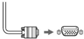
1 Connecting your monitor to your computer
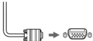
Video signal cable of the monitor
to HD15 of the connecting computer
Connecting to a Macintosh or compatible computer
When connecting this monitor to a Macintosh computer, use the Macintosh adapter if necessary. Connect the Macintosh adapter to the computer before connecting the cable.
2 Turning on the monitor and computer
1 Connect the power cord to the monitor and press the (power) switch to turn on the monitor.
2 Turn on the computer.
No need for specific drivers
This monitor complies with the "DDC" Plug & Play standard and automatically detects all the monitor's information. No specific driver needs to be installed to the computer. The first time you turn on your PC after connecting the monitor, the setup Wizard may appear on the screen. In this case, follow the on-screen instructions. The Plug & Play monitor is automatically selected so that you can use this monitor.
Notes
- Do not touch the pins of the video signal cable connector.
- Check the alignment of the HD15 connector to prevent bending the pins of the video signal cable connector.
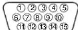
HD15 input connectors
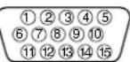
| Pin No. | Signal |
| 1 | Red |
| 2 | Green (Sync on Green) |
| 3 | Blue |
| 4 | ID (Ground) |
| 5 | DDC Ground* |
| 6 | Red Ground |
| 7 | Green Ground |
| 8 | Blue Ground |
| Pin No. | Signal |
| 9 | DDC HOST 5V* |
| 10 | Ground |
| 11 | ID (Ground) |
| 12 | Bi-Directional Data (SDA)* |
| 13 | H. Sync |
| 14 | V. Sync |
| 15 | Data Clock (SCL)* |
- DDC (Display Data Channel) is a standard of VESA.
Adjustments
Navigating the menu
1 Press the MENU/OK button to display the main menu.
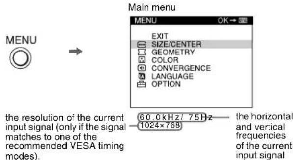
2 Move the joystick / to highlight the main menu you want to adjust and press the MENU/OK button.

3 Move the joystick / to highlight the sub menu you want to adjust. Then move the joystick / to make adjustments.
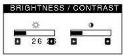
Adjusting the brightness and contrast
Brightness and contrast adjustments are made using a separate BRIGHTNESS/CONTRAST menu. These adjustments are effective for all input signals.
1 Move the joystick in any direction to display the BRIGHTNESS/CONTRAST menu.
2 Move the joystick / to adjust the brightness (O), and to adjust the contrast (O).
On-Screen menu adjustments
| Main menu icons and adjustment items | Sub menu icons and adjustment items | ||
| ←→ | Adjusting the size or centering of the picture*1 | □ | Horizontal position |
| ← | Horizontal size | ||
| □ | Vertical position | ||
| □ | Vertical size | ||
| ∞ | Enlarge/reduce | ||
| Adjusting the shape of the picture | ○ | Rotating the picture*2 | |
| ○ | Expanding or contracting the picture sides*1 | ||
| ○ | Shifting the picture sides to the left or right*1 | ||
| ○ | Adjusting the picture width at the top of the screen*1 | ||
| ○ | Shifting the picture to the left or right at the top of the screen*1 | ||
| Adjusting the color of the picture*2 | See “: To adjust the color of the picture”. | ||
| Adjusting the convergence*2 | ○ | Horizontally shifts red or blue shadows | |
| ± | Vertically shifts red or blue shadows | ||
| A | Selecting language Selecting the oh-screen menu language *3 | ||
| Additional settings | ○ | DEGAUSS: demagnetizes the monitor. | |
| ←○ | MOIRE ADJUST: Minimises moir*4 | ||
| ↔← | See “To reset the adjustment”. | ||
| ○- | Protecting adjustment data (CONTROL LOCK) *5 | ||
* This adjustment is effective for the current input signal.
*This adjustment is effective for all input signals.
*3 Language Menu
- ENGLISH - NEDERLANDS: Dutch
FRANCAIS: French • SVENSKA: Swedish
- DEUTsCH: German - Prrsskan
- ESPANOL: Spanish - 日本語: Japanese
ITALIANO:Italian
*4 Example of Moire

*5 Only the (power) switch, EXIT, and ON (CONTROL LOCK) menu will operate.
: To adjust the color of the picture
The COLOR settings allow you to adjust the picture's color temperature by changing the color level of the white color field. Colors appear reddish if the temperature is low, and bluish if the temperature is high. This adjustment is useful for matching the monitor's color to a printed picture's colors.
Adjustment items
You can select the preset color temperature from 5000K or 9300K. The default setting is 9300K. If necessary, you can make additional fine adjustments to the color by selecting
: To reset the adjustment
The RESET option erases your customized settings. To restore your monitor to the factory settings, refer to the following steps.
Resetting the adjustment for current input signal
Move the joystick
Resetting the adjustment for all input signals
Hold the joystick for 2 seconds.
Note
When "reset the adjustment for all input signal" is activated, the customized language selection goes back to the default language of English.
Troubleshooting
■No picture
If the (power) indicator is not lit
- Check that the power cord is properly connected.
- Check that the (power) switch is in the "on" position.
The (power) indicator is orange - Check that the video signal cable is properly connected and all plugs are firmly seated in their sockets.
- Check that the HD15 video input connector's pins are not bent or pushed in.
- Check that the computer's power is "on".
- The computer is in power saving mode. Try pressing any key on the computer keyboard or moving the mouse.
- Check that the graphic board is completely seated in the proper bus slot.
If the 心 (power) indicator is green or flashing orange
- Use the Self-diagnosis function.
■Picture flickers, bounces, oscillates, or is scrambled
- Isolate and eliminate any potential sources of electric or magnetic fields such as other monitors, laser printers, electric fans, fluorescent lighting, or televisions.
- Move the monitor away from power lines or place a magnetic shield near the monitor.
- Try plugging the monitor into a different AC outlet, preferably on a different circuit.
Try turning the monitor 90^ to the left or right. - Check your graphics board manual for the proper monitor setting.
- Confirm that the graphics mode and the frequency of the input signal are supported by this monitor (see "Preset mode timing table" on page i). Even if the frequency is within the proper range, some graphics board may have a sync pulse that is too narrow for the monitor to sync correctly.
- Adjust the computer's refresh rate (vertical frequency) to obtain the best possible picture.
■Picture is fuzzy
- Adjust the brightness and contrast.
- Dcgauss the monitor.*
- Adjust for minimum moir.
■Picture is ghosting
- Eliminate the use of video cable extensions and/or video switch boxes.
- Check that all plugs are firmly seated in their sockets.
■Picture is not centered or sized properly
- Adjust the size or centering. Note that with some input signals and/or graphics board the periphery of the screen is not fully utilized.
- Just after turning on the power switch, the size/center may take a while to adjust properly.
Edges of the image are curved
- Adjust the geometry.
■Wavy or elliptical pattern (moire) is visible - Adjust for minimum moirc.
- Change your desktop pattern.
Color is not uniform
- Degauss the monitor.* If you place equipment that generates a magnetic field, such as a speaker, near the monitor, or if you change the direction the monitor faces, color may lose uniformity.
■White does not look white - Adjust the color temperature.
Monitor buttons do not operate ( appears on the screen)
If the control lock is set to ON, set it to OFF.
Letters and lines show red or blue shadows at the edges - Adjust the convergence.
A hum is heard right after the power is turned on
- This is the sound of the auto-degauss cycle. When the power is turned on, the monitor is automatically degaussed for five seconds.
- If a second degauss cycle is needed, allow a minimum interval of 20 minutes for the best result. A humming noise may be heard, but this is not a malfunction.
On-screen messages
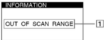
1 If "OUT OF SCAN RANGE" appears:
This indicates that the input signal is not supported by the monitor's specifications. Refer to the following remedies.
- Check that the video frequency range is within that specified for the monitor. If you replaced an old monitor with this monitor, reconnect the old monitor and adjust the frequency range to the following.
Horizontal: 30 - 85kHz
Vertical: 48 - 170Hz
1 If "NO INPUT SIGNAL" appears:
This indicates that no input signal is present. Refer to the following remedies.
- Check that the video signal cable is properly connected and all plugs are firmly seated in their sockets.
- Check that the HD15 video input connector's pins are not bent or pushed in.
- Check that the computer's power is "on."
- Check that the graphic board is completely seated in the proper bus slot.
1 If "MONITOR IS IN POWER SAVE MODE" appears:
This indicates that the computer is in power saving mode. This message is displayed only when your computer is in a power saving mode and you press any one of the buttons on the monitor. Refer to the following remedies.
- Try pressing any key on the computer keyboard or moving the mouse.
- Check that the computer's power is "on."
- Check that the graphic board is completely seated in the proper bus slot.
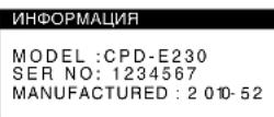
To display this monitor's name, serial number, and date of manufacture.
While the monitor is receiving a video signal, press and hold the MENU/OK button for more than five seconds to display this monitor's information box.
INFORMATION
MODEL:CPD-E230
SER NO: 1234567 MANUFACTURED: 2001-52
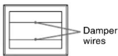
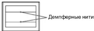
If thin lines appear on the screen (damper wires)
These lines do not indicate a malfunction; they are a normal effect of the Trinitron picture tube with this monitor. These are shadows from the damper wires used to stabilize the aperture grille. The aperture grille is the essential element that makes a Trinitron picture tube unique by allowing more light to reach the screen, resulting in a brighter, more detailed picture.
Self-diagnosis function
This monitor is equipped with a self-diagnosis function. If there is a problem with your monitor or computer(s), the screen will go blank and the (power) indicator will either light up green or flash orange. If the (power) indicator is lit in orange, the computer is in power saving mode. Try pressing any key on the keyboard or moving the mouse.
If the 心 (power) indicator is green
1 Disconnect the video input cable or turn off the connected computer.
2 Press the (power) button twice to turn the monitor off and then on.
3 Move the joystick for 2 seconds.
If all 4 color bars appear (white, red, green, blue), the monitor is working properly. Reconnect the video input cables and check the condition of your computer(s).
If the color bars do not appear, there is a potential monitor failure. Inform your authorized Sony dealer of the monitor's condition.
If the (power) indicator is flashing orange
Turn the monitor OFF and then ON.
If the (power) indicator lights up green, the monitor is working properly.
If the (power) indicator is still flashing, there is a potential monitor failure. Count the number of seconds between orange flashes of the (power) indicator and inform your authorized Sony dealer of the monitor's condition. Be sure to note the model name and serial number of your monitor. Also note the make and model of your computer and graphics board.
Specifications
CRT 0.24mm aperture grille pitch (center) 17 inches measured diagonally 90-degree deflection FD Trinitron
Viewable image size Approx. 327× 243mm (w/h) (12^7 / 8× 9^5 / 8 inches)
Viewing image Approx. 406 mm (16.0 inches)
Resolution
Maximum Horizontal: 1600 dots
Vertical: 1200 lines
Recommended Horizontal: 1024 dots
Vertical: 768 lines
Standard image area
Approx. 312 × 234 ~mm (w/h)
(12^3 / 8 × 9^1 / 4 inches)
Deflection frequency
Horizontal: 30 to 85kHz
Vertical: 48 to 170Hz
AC input voltage/current
100 to 240 V, 50-60 Hz, Max. 1.7 A
Power consumption Approx.115 W
Operating temperature
10^ to 40^
Dimensions Approx. 402× 418× 421mm (w / h / d)(15^7 / 8× 16^1 / 2×
16/8 inches)
Mass Approx. 19kg (41.9 lb)
Plug and Play DDC2B/DDC2Bi
GTF
Supplied accessories
Power cord (1)
Warranty card (1)
Notes on cleaning the screen's surface (1)
This instruction manual
Preset and user modes
When the monitor receives an input signal, it automatically matches the signal to one of the factory preset modes stored in the monitor's memory to provide a high quality picture (see "Preset mode timing table" on page i). For input signals that do not match one of the factory preset modes, the digital Multiscan technology of this monitor ensures that a clear picture appears on the screen for any timing in the monitor's frequency range (horizontal: 30 - 85kHz , vertical: 48 - 170Hz ). If the picture is adjusted, the adjustment data is stored as a user mode and automatically recalled whenever the same input signal is received.
Power saving function
This monitor meets the power-saving guidelines set by VESA, ENERGY STAR, and NUTEK. If no signal is received by the monitor from your computer, the monitor will automatically reduce power consumption as shown below.
| Power mode Power consumption (power) indicator | |
| normal operation | ≤ 115 W green |
| active off* | ≤ 3 W orange |
| power off | 0 W (Approx.) off |
- When your computer is in active off mode, MONITOR IS IN POWER SAVE MODE appears on the screen if you press any button on the monitor. After a few seconds, the monitor enters the power saving mode again
Design and specifications are subject to change without notice.
Precautions
Warning on power connections
- Use the supplied power cord. If you use a different power cord, be sure that it is compatible with your local power supply. For the customers in the UK If you use the monitor in the UK, be sure to use the supplied UK power cable.
Example of plug types

for 100 to 120 V AC for 200 to 240 V AC for 240 V AC only
- Before disconnecting the power cord, wait at least 30 seconds after turning off the power to allow the static electricity on the screen's surface to discharge.
After the power is turned on, the screen is demagnetized (degaussed) for about 5 seconds. This generates a strong magnetic field around the screen which may affect data stored on magnetic tapes and disks placed near the monitor. Be sure to keep magnetic recording equipment, tapes, and disks away from the monitor.
The equipment should be installed near an easily accessible outlet.
Installation
Do not install the monitor in the following places:
- on surfaces (rugs, blankets, etc.) or near materials (curtains, draperies, etc.) that may block the ventilation holes
- near heat sources such as radiators or air ducts, or in a place subject to direct sunlight
- in a place subject to severe temperature changes
- in a place subject to mechanical vibration or shock
on an unstable surface - near equipment which generates magnetism, such as a transformer or high voltage power lines
- near or on an electrically charged metal surface
- inside an enclosed rack
Maintenance
- Clean the screen with a soft cloth. If you use a glass cleaning liquid, do not use any type of cleaner containing an anti-static solution or similar additive as this may scratch the screen's coating.
- Do not rub, touch, or tap the surface of the screen with sharp or abrasive items such as a ballpoint pen or screwdriver. This type of contact may result in a scratched picture tube.
- Clean the cabinet, panel and controls with a soft cloth lightly moistened with a mild detergent solution. Do not use any type of abrasive pad, scouring powder or solvent, such as alcohol or benzine.
Transportation
When you transport this monitor for repair or shipment, use the original carton and packing materials.
Use of the tilt-swivel
This monitor can be adjusted within the angles shown right. To turn the monitor vertically or horizontally, hold it at the bottom with both hands. Be careful not to pinch your fingers at the back of the monitor when you tilt the monitor up vertically.
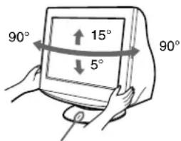
Centering line
Table des Matieres
Configuration. 3
Réglages. 4
Dépannage 6
Spécifications 7
Précautions 8
Appendix
Preset mode timing table
TCO'99 Eco-document. .Couverture dos
Plug and Play DDC2B/DDC2Bi
GTF
Accessoires fournis Cordon d'alimentation (1)
Plug and Play DDC2B/DDC2Bi
GTF
MANUFACTURED 2001-52
Horizontal: 30 a 85 kHz
Vertical: 48 a 170Hz
Corriente/tension de entrada de CA
100 a 240 V, 50 - 60 Hz, Max. 1,7 A
Consumo de energia
Aprox. 115 W
Plug and Play DDC2B/DDC2Bi
GTF
Accessorindotazione
IoproToBka K pa6ote. 3
PereynilpoBka 4
YcTpaHEnHe HncnPaBHOCTe 6
TexnueckxapaKTepeNtuk 7
Mepblnpedoctopoxhoctn. 8
Appendix
Preset mode timing table
TCO'99 Eco-document. 3aHnKpblka
T r i n"i3aperoctpnpoBaHHa TOproBaH Mapka Sony Corporation.
Macintosh ABnAeTc TropBOm MapKo Apple Computer, Inc., 3apernctpupobAHHO B CUSA n dpynx ctpahax.
- Windows 3 u MS-DOS 1BnHOTc 3apeHCTpnpOBAHHbIMT TopOBbIMN Mapkamn Microsoft Corporation B CUSA n dpyrx cTpaHax.
- IBM PC/AT v VGA ABNIOCT3apeHCTpnpoBaHHbIMT TopROBIMn Mapkam IBM Corporation B CUSA.
- VESA IN DDC "BRAJIOCTA TOPROBIMI MapKAMI Video Electronics Standard Association.
ENERGYSTAR ABNAREcMapKo3apeRnCTpnpOBaHHOBCLLA.
- OctaIbHbIe Ha3BaHnIPOyKDTOB, yONOMHytIbe B 3OTM DOKYMHTe, MORYT ABNtCB3aPepNCtpuPoBAHHbIMTOPTOBbIMM MapKAMIN NNI TOPTOBbIMM KAPAMC0OTBEETCTBYOUIX BNAJdJIbUEB.
BdaIbHeMcMbOJIb“TM"H“@”He yNOMHaOTcB 3TOM pyKOBOdCTBE.
Pojrotobka K pa6oTe
1 NpoknueHne MOHTopa K KOMnbIOTepy
Ka6eIb BnDoeocnHaJa MOHITOPa
KpasaHMyD15 noKaHNoaMeMOrO KOMbIbOTepa
IopKJIoueHne K KombIoTepy Macintosh nN COBMEcTUMOMy C Hm
PnnoKIOUeHm 3TOO MOHITOPa K KombIOTepy Macintosh nCNoB3yTe npn Heo6xOuMocTn aanTep nn Macintosh. AanTep nn Macintosh Heo6xOuMo noKnOuaTb K KOMNbIOTepy Do noKnIOUeHm KaBEn.
2 BkJIIOUeHHe MOHITOpa N KOMIbIOTepa
1 NookJIIOHnTE Ka6eJIb NHTAHN K MOHNTOpY HAXMnTe KHONKy NHTAHN OTO6bI BKIOHnTb MOHnTOP.
2 BkIIOHTe KOMNbIoTeP.
CneuaHbIe npaBepbHe Tpe6yOTc
DaHHb MOHHTOP OTBeayetTre6oBaHnM cTahdapTa DDC" Plug & Play, n KOMbIbOTep ATOMATUeCKN 0hApHyKNaBET BcO INΦOpMaunHO MOHHTope. Heo63aTeNbHo yCtahAbnBaTb Ha KOMbIbTepe KaKeNHe60 CneuAnbHbIe dpaiBepbI.
Pn npBbOM BkIOUeHm NIK nOcNE NOKIOUeHm MOHtOpa Ha 3KpaHE MOKTe NOrBtCBdNAnorOBoe OKHO IpOrpAmMbYcTaHOBKn. B 3TOM Cnyae cNeyIte YKa3AHm Ha 3KpAe. MoHtOp Plug & Play BblbpaeTcR abTomaTneck, YTO No3BOJnE rcpaY hauTaB erO NCNoJIb3OBaTb.
PpmeaHn
He npikacaiTecb K wTbipkam pa3bema Ka6eBnDaeocnHaHa.
-Поверъпразвьнocьтбрсполжени раьema HD15 дпгдпотьрашени сгбаништьрьков раьema kaбени BИDEOCIRHILA.
BxohbpepaebmHd15
YcTpaHHe HEnCnPaBHOCTeI
HETn3o6paXeHHN
Ecnn mHdkaTop (nHTaHne) He ropnt
- PpOBepbTe, npaBnIbHO nI NOkNIOUeyeK a6eJIb NITaHIN.
- PpOBepeTe, HAXoIHTcA IN BBkNIOHATeINb (NTaHHe) B NOJoxEHN "ON" (BKn.).
HnKaTOp nTaHnO rOpnt OpaXKeBbIM - Y6eIntecb,HTO Ka6eIb BnDEoCnHana NOkKIOueH npaBnIbHO, IN BCE pa3beMbl HaexKHO BCTaBnEhbl CBONrHe3da.
Y6eIInTeB,HTO HN OIM IN3 WITbIPKOBbIX KOHTAKTOB BnDEoKa6aEIN HD15 He ABnRETCa N3OrHyTbIM He yTONJIeH BYTyPb BnIKN. - PpOBepeTe, HAXOJNTcR Nn BBKNIQUaTeIb KOMNbIOTepa B NOJOKeHm "on" (BKn.).
KOMNbIbTeP HApOaNTCB P eXIMMe 3koHOMMn 3heprm. Nonpoobynte haoTaB IIObOy KnaBnUy Ha KaNbaNAtype KOMNbIbTePa INI nepeDBHyTb MbluB. - Y6eIntecb, YTO rpaΦnueckn aIaIaTep npaBnIbHO nHaIeXHO 3aKpeIenH B pa3beMe NOkKnIOHeH N K IINHe.
Ecnn HndkaTOp nTaHn (nTaHne) ropnt 3eneHbIM nn Muraet opaXkeBbIM
- IcnoJb3yIte cyHKuHcMoDnaHrOCTnKn.
CkaKn,dpoxKaHne,BONHO6pa3HbIE KOe6aHnNnnnomexn 306paKeHH
V30npyTe n yctpaHnte IIO6bIe noTeHuaNbHbIe nCTOCHNKn 3NEKTPueCckNX INM MaHTNHbIX NOJIe, HApNIMep, DpyTne MOHNTOpbl, Na3epHbIe npHTpe, 3NEKTPueCckNe BHTNUrTObpbl, fnoyopeCteHTBHe lamNbI hIN TeneBn3Opbl.
- OTOBMBHe TO MOHITTOP IOANJIbJIe ue IT HINNJI 3JIeKTPoNTAHNAI JIMVCTAHOBOHTE BOJIe HERO MARHINTHyI 3KpaH.
- Ponnpo6yute NIOKNIOHTb MOHITOP K dpyro cTeBOI po3eTke, KeNaTeBHO OT dpyrTO KOHTypa.
-Nonpo6ynte NOBepHyTb MOHITOp Ha 90^ BnEBO INN BnpaBO.
- O6paTInTeB K pyKOBoDCTBy NO rpaΦnHeCKOMy aadAnTepy, YTObI pyPOBepNTb, PpABINbHbe IIN npapAMetPbI yCTaHOBJIeHbI dIa MOHHTOPa.
- YdOcTOBepbTecb B TOM, YTO rpaФnueckn peXIM n aCToTa BXoDHOro CnHana COOTBETCTBYOT XapaKTEpNCTHKAM MOHTOPa (cm. pa3den "Preset mode timing table" Ha cTp. i).Дaxe B NOxODaIeM qACTOTOM dnaIa3OHe HeKOtbpI rpaФnueckne aIaNTpebI noAoiT CnIbKOM y3Kn IJRA KOpEKTHOI CNHXPOH3aIIMMOHTOPCAHXPONH3npUOHNIMNIVbc.
IIOCTPOITe TcAChTOTy pereHepaun KOMNbIOTepa (TcAChTOY BEPTKAnBHO pa3BePTKN) IINI NOLUYEHNR ONTMAlBHOrO M3O6paKeHHN.
HeeyKoe n3o6paXeHne
-ПОДСТРОЛТЕ KOHTPACTHOBИRPKOCTB.
- BbINOJIHnTe pa3MaIrHuNvBaHHe MOHITopa.*
HacptpoTe MyapOBbI pOH, cDenaB erO MNHMaJIbHbIM.
"TeHn"Ha n3o6paXKeHN
He nCnoB3yTe yDInHnTeN BnDeOka6ene N KOMMyTaTOpbBnDeOcnHana.
- PpOBepe,HaDExKHOJIN3aKpeHbIB CBOxTHe3dax Bce pa3beMbl.
HenpaBnIbHbIe ceHTpOBKa nI npa3Mep n3o6paKeHHA
IIOCTpoTe pa3MeP HIN OTUeHTpPyte NT06paXeHne. CnEduT NMeTb B BNDY, YTOB COeTaHMH BXOJHbIX CNrHAIOB C onpeDeEHBMIM rpaFNeCKMm PNaTAMn Kpaar 3KpaHa NCNONb3yOTcHe NONHOCTbUo.
Cpa3y nocle haxatn KhoNkn NITAHIN, 3IO6paXeHne HekOTOpoe BpeM NoCTpaNbaETcNo pa3Mepy u eHTpy 3KpHa.
KpaHn3o6paXeHHNcKpNBHeHbI
- PoiDCTpoIte reOMeTpueckne npaMeTpbl.
BolnctbIe nn MyapOBbI pa3BODbl Ha 3KpaHe
- HactpoTe MyapOBbI ΦoH, CdeJaB erO MHHMaJIbHbIM.
- Cmehnte pncyHok pa6oHero cToJa.
■HepaBHomepaHAn OKpaca H3o6paXeHHA
- BbINONHIne pa3MaHnUHbAHe MOHTOpa. * OndHopoAnOcTb UBETA MoKET HApUaTHcB aTex Cnyuayx, KOrDa B6N3n MOHTOpa HaxoJATC nCTOnHUYmARHHTHO IONr, TaKne KaK rPOMKOROBOPHTENI, INI pNn NOBOPOTE MOHTOpA.
6eBbI UBeT He BbIRIANT 6eBbIM
- Póndtrope YeBetoByIO TemnepaTpy.
KHOKNMOHNTOPaHe pa6oTaIOT(Ha 3KpaH e NORBJIReTc
EcIn cyHKcua 6nOKuropBKn opranOB ynpaBHeH BAKNIOueHa -noJoxeHne BkJI, npeBeNeTe ee B noJoxeHne BblKJI.
KpachbIe nHn CnHne OTteHKn NO Kpaam 6ykb NJI JInnHm
- POnCTPOITe COBMeUeHnE UBeTOB.
Cpa3y nocne BkIIOUeHn MOHTopa pa3daeTc HnpoDoJXKTeJIbHOe rydeHne
3TOT 3BYK cNYTcByET npoueccy ABTomuheckoro paaMarHnHbAHIN. IIOeB KNIHOHNaTHN B TeueHne np6n3ntelbO 5 cekyH nponcxoHNT ABtomauheckoe paMaMarHnHbAHNE TpykMOHHTOPA.
* ECnn noTpe6yeTeCnOBToPntb npouecc paMaHmNVAHn, 3TO MoXHO CDenAaTB KAK MHNMyM Yepe3 20 MNHyT, dNn TORO YTO6bl NOnyTuHnYnHpE3yJbTaT. YdrauN 3ByK, KOtOpBn CnblIeH, He ABnETc HEnncnPabHOCTbIO.
3KpaHHbIe coo6ueHnA
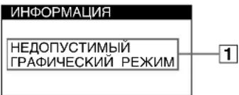
1EcHnHa3KpaHeNoABJIeTcCoO6ueHHe "HEDOYCTUMbI INrPAΦNUECKNPEXIM":
Yka3bIbAe HTo YTO BXOHOH CNHAn He COOTBeTCTByET XapaKTePnCTnKAM MOHTopa. O6paTnTeCb K CNeDyIOuM M DeNCTBnAM N0 YCTpAHEnHO HeNoJaOK.
- Y6eHntecb, YTO qACTOTHbI dHaNa3OH COOTBeTCTByET TexHnueckKIM napaMeTpam MOHTopa. EcnI daHHaM oMeIb yctHaBaINBaeTc BmETo CTaporo MOHTopa, BepHnTe npExHN MoHTop HA MeCTO NIOCTPOITe YAcT0THbI dHaNa3OH CORNACHO CNEyIOUIM TexHnueckKIM napaMeTpam. Iro pRn3oHTan: 30 -85 KtI PoBpTKaJI:48-170 T
1EcnHa3KpaHeNoABnETCaCOo6eHne“HET BXODHO CnHAJA":
Yka3bIbae HATO, YTO BXO.HOH CNHJN OTCyTCTByET.
O6paTInTeCb K CNEyIOUIM DeiCTBnM NO yCTpaHEHIO
HENOLaDOK.
- Y6eInTeScb, yTo Ka6eIb BnIeOcHnHa INoIKnIOueH npaBnIbHo, a BCE pa3BeMbI HaIeXHO BCTaBnEhBi B CBOI rHe3da.
- Y6eInTeCb, yTO Hn OOnH n3 WbIpbKOBbIX KOHTaKToB BnDeOka6ena HD15 He ABNaETcN 30rHyTbIM n He yToPJIeH BHyTpB BnIKn.
Поверпг,нхдсгл Вькчateь KMьTepaВ NOLOжен "on"(ВКЛ). - Y6eHNTecb, yTo rpaFnuueckn aadTep npaBnIbHo nHaDeXHO 3akpeIJIeB pa3bEme NOkNIOUeHnK WInHe.
1EcHnHa3KpaHe NOBBJIeTc COO6UeHHe MOHITOP B PEXKIME 3HEPROCEPEXKEHNA":
Yka3bIbaet Ha To, YTO KOMnbIOTep HaxoDITcB B pexnme 3KOHOMM 3HePmN. DaHHOE COO6eHne OTObpaKaTeCn Ha 3KpaHE TObKO B TOM Cnyae, KOrDa KOMNbIOTeP HaxoDITcB B pexnme 3KOHOMM 3HePmN. N HaxaTaNIOBaKHONka H MoHTope. Obpatntecb K cJeNyUcIM M DeiCTBnMn NO yCTpHaEHNO HENOpJADOK.
- Nonpo6yIte HaxaTb IIO6yIO KnaBnUHa NaBnATypeKOMIbOTepeNII NpeDBrHHTbMbIb.
Поверпг,нхд.Tаи ВькюаTeь KMьTepaВ NOJOKeHm "on"(ВКЛ). - Y6eHITecb, yTO rpaFNUeCKn aADANTEp npaBnIbHo nHaDeXHO 3akpeJIeB bpa3beMe NOkJIIOHeH K WInHe.
OTo6paXeHHe Ha3BaHnMa MoDeIIMoHHTopa, cepHOrO Homepa I DaTbI BbInycka.
B MOMENT NOLUYEHNA
MOHITOPOM BUNDEOCNTHANA
HAJKMITE KONKYN MENU/OK HENOTNYCKAte ee B TeueHne He
MEHNE 5 CekYd, YTO6bI
BBIBECTN Ha 3KpaH
HOpMaunOHHOOKHO
DAHHOIMoJINMOHTopa.
DemphepHbIe HHTN
3TNIMHHeCBnTeBcTByOToHEncnpabHoctn IN ABJIOTCAOBHbIM 3PfEKtOM 3NEKTPOHO-nyeBbIX Tpy6OK Trinitron,KOTOpBE yCTaHaBNIbaOTcB DaHHbIX MOHITOPax. 3TO TEHN dEmIppehBX HInTE, KOTOpBE racrB N6paMIO anepTyPho peWetKN.AneptypharpeWetKa -3TO OHeB BaxHbI aMeENT, KOTOpBI dEnaET AEKeTPoHO-NyBeBbIE Tpy6Kn Trinitron yHNkAlbHbIMN IOEcecNeuBaET 60nee INHTeHCNBbIE CBETbIte ToHa Ha 3KpAHe, 6Janoapar Yemy I306paXeHne cTaHOBITcApYe I OTyETINBee.
Функця самоюнгостик
JaHHb MOHITOP OCHaUeH cyHKuEe CAMoDnAHROCTKKn. Ecnn BO3HNKaET KAKaJ-NI60 np6bnema C MOHITOPOM NIN KOMNBIOTepOM (KOMNBIOTepaM), 3KpaH OHIIaETCa, a INHdNKaTOp (NIHTaHne) ROPNT 3eNEbIM NIN MIRAEt OPAHKeBBiM. ECnn INHdNKaTOp (NIHTaHne) ROPNT OPAHKeBBiM, TO KOMBIOTep HaxoNDITCB PEXNIME 3KOHOMN 3HePnN. NonpO6yIte HaxaTb IIObYIO KlaBnWHa Na KlaBnAType NIN nepeDbNHHTb MbIb.
Ecnn HndkaTop (NHTaHne) ropnt 3eJeHbIM
1 OToeHNHTe Ka6enb BnDEOBXoDa NnBbIKIOHTe NOcEOHNHeHHbK MOHNTOpy KOMnbOTep.
2 HaKMnte KONky NITaHnA DBaXkDbI, 4To6bI BbIKNIOHTb MOHtOp n 3aTeM BKIOHTb.
3 Nepemecnte dxKoNCTnK Ha 2 ceKyHdbI.
Ecni noBbTcB CeYtBipe UBeTHbIe NIOOckn (6enoro, KpaCHoro, 3eJeHoro, CInero), TO MOHTop paBoTaet npaBnIbHo. BHObNoCoEduHITe KaBEn K BuDeOBXoJam npOBepbTe COCToAHHe KOMNbIOTepa.
EcIN ZBEThHe NOLOCKH He NOBIAOTcA,TO MOHTOp, BO3MOxHO, HEnCnpaBEN. POnHΦOpmNpyTe MECTHO OcHnAIBHO DInepa Sony O CoCToAHm CBOero MOHTopa.
Ecnn HndkaTop (nntaHne) MrraeT opaHXeBbIM
BbIKIOHTe MOHITOp, a 3aTEM CHOBA BKJIIOHTe.
Ecnn HnDkaTOp (Ntahne) TropNT 3eHbIM, TO MOHTop pa6Otaet HopMaJIbHO.
Ecni HnDnKaTOp (nITaHne) npoOJkaeT MraTb, To, BO3MOxHO, MOHTOP HeNCpAbEH. CocHTaTe KOINcECTBO CEkyH B INHTepBaIax Mekdy 3aropAHem HnDnKaTopa
100-240B,50-60Γμ,mακc.1,7A
Notpe6nHaMaMoHocTb
Pn6n.115Bt
Pa6o4a TemnepaTpa
10^ - 40^
402×418×421MM(W/B/r)
Macca Pp6n.19 K
Plug and Play DDC2B/DDC2Bi
GTF
BxOJaUe B KOMnEeT npHaJdHexHOctu
Ka6eBnTuHaHn(1)
TapaNTnHbI TaIOH (1)
PnimeaHn no nCTKe NOBepxHOCTn 3KpaHa (1)
Hactoaa Hnctpykun no 3Kcnnyatau
PpeyctaHOBHeHHbI n NOJIb3OBaTeJbckn peKmbl
Pn npneMe BXoHoro CnHana MOHNTop ABTOMATueeKn
CORIACOBbBaET erO COnHM n3 peKIMoB, ppeDbapnteHbHO
yCTaHOBHeHHbIX Ha 3aBoDE IN XpaHuaXcB NnAMrN MOHITOPa, dIa
06ecneeynBbICOKOKaueCTBeHHoro n3o6paXeHn (cm. pa3dien
"Preset mode timing table" Ha ctp. i).ДЯ BXOДьx CnHаIOB, He
COOTBETCTBYIOUX HN ODNHY 3aBOcknx peKIMOB, C NOMOsbIO
TEXHONORIN UPOBOORMOyIbTnCKaHnpOBaHN DaHHOro MOHTopa
POM3B0A3T8C BHeACPTpOKnI, Heo60xDMbIe IaNnIOyHcH eTeKTOI 13604paXeHJI pni LIOOJI CINHXPOHN3aUMI b Eero cactOTHom dIana3OHe
(ropn30HTaBHa: 30-85KΓu, BepTnKaIbHa: 48-170Γu).
Pn perynpOBKe n3o6paXeHn DaHHbIe HAcTPOKn 3aHOcATC B
NAMATb KaK NOB3OBaTeJbckn peXIM n aBTOMaTneCKN BblBaOTc
n3 Hee KaKdbi pa3 npn NonyeHm daHHoro BXoDHoro CurnHa.
yctaHOBJIeHHbIM VESA,ENERGY STAR NUTEK. EcnHa MoHHTOp He
noaetcCnHcN C noKNoeHHOro KOMnbTepa, MOHTOP 6ydet
ABTOMaTnueckn CHNXKaTb NtPte6JIeHHe 3HeprN, KaK nOKa3aHO HIXKe.
Plug and Play DDC2B/DDC2Bi
GTF
Medfoljande tilbehö
Natkabel (1)
Garantisedel (1)
On-screen Menu-installingen
Plug and Play DDC2B/DDC2Bi
GTF
If the input signal does not match one of the factory preset modes above, the Generalized Timing Formula feature of this monitor will automatically provide an optimal image for the screen as long as the signal is GTF compliant.
TCO'99 Eco-document

■Congratulations!
You have just purchased a TCO'99 approved and labelled product! Your choice has provided you with a product developed for professional use. Your purchase has also contributed to reducing the burden on the environment and also to the further development of environmentally adapted electronics products.
Why do we have environmentally labelled computers?
In many countries, environmental labelling has become an established method for encouraging the adaptation of goods and services to the environment. The main problem, as far as computers and other electronics equipment are concerned, is that environmentally harmful substances are used both in the products and during their manufacture. Since it is not so far possible to satisfactorily recycle the majority of electronics equipment, most of these potentially damaging substances sooner or later enter nature.
There are also other characteristics of a computer, such as energy consumption levels, that are important from the viewpoints of both the work (internal) and natural (external) environments. Since all methods of electricity generation have a negative effect on the environment (e.g. acidic and climate-influencing emissions, radioactive waste), it is vital to save energy. Electronics equipment in offices is often left running continuously and thereby consumes a lot of energy.
What does labelling involve?
This product meets the requirements for the TCO'99 scheme which provides for international and environmental labelling of personal computers. The labelling scheme was developed as a joint effort by the TCO (The Swedish Confederation of Professional Employees), Svenska Naturskyddsforeningen (The Swedish Society for Nature Conservation) and Statens Energimyndighet (The Swedish National Energy Administration).
Approval requirements cover a wide range of issues: environment, ergonomics, usability, emission of electric and magnetic fields, energy consumption and electrical and fire safety.
The environmental demands impose restrictions on the presence and use of heavy metals, brominated and chlorinated flame retardants, CFCs (freons) and chlorinated solvents, among other things. The product must be prepared for recycling and the manufacturer is obliged to have an environmental policy which must be adhered to in each country where the company implements its operational policy.
The energy requirements include a demand that the computer and/or display, after a certain period of inactivity, shall reduce its power consumption to a lower level in one or more stages. The length of time to reactivate the computer shall be reasonable for the user.
Labelled products must meet strict environmental demands, for example, in respect of the reduction of electric and magnetic fields, physical and visual ergonomics and good usability.
Below you will find a brief summary of the environmental requirements met by this product. The complete environmental criteria document may be ordered from:
TCO Development
SE-114 94 Stockholm, Sweden
Fax: +46 8 782 92 07
Email (Internet): development@tco.se
Current information regarding TCO'99 approved and labelled products may also be obtained via the Internet, using the address: http://www.tco-info.com/
■Environmental requirements
Flame retardants
Flame retardants are present in printed circuit boards, cables, wires, casings and housings. Their purpose is to prevent, or at least to delay the spread of fire. Up to 30% of the plastic in a computer casing can consist of flame retardant substances. Most flame retardants contain bromine or chloride, and those flame retardants are chemically related to another group of environmental toxins, PCBs. Both the flame retardants containing bromine or chloride and the PCBs are suspected of giving rise to severe health effects, including reproductive damage in fish-eating birds and mammals, due to the bio-accumulative* processes. Flame retardants have been found in human blood and researchers fear that disturbances in foetus development may occur.
The relevant TCO'99 demand requires that plastic components weighing more than 25 grams must not contain flame retardants with organically bound bromine or chlorine. Flame retardants are allowed in the printed circuit boards since no substitutes are available.
Cadmium**
Cadmium is present in rechargeable batteries and in the colour-generating layers of certain computer displays. Cadmium damages the nervous system and is toxic in high doses. The relevant TCO'99 requirement states that batteries, the colour-generating layers of display screens and the electrical or electronics components must not contain any cadmium.
Mercury**
Mercury is sometimes found in batteries, relays and switches. It damages the nervous system and is toxic in high doses. The relevant TCO'99 requirement states that batteries may not contain any mercury. It also demands that mercury is not present in any of the electrical or electronics components associated with the labelled unit.
CFCs (freons)
The relevant TCO'99 requirement states that neither CFCs nor HCFCs may be used during the manufacture and assembly of the product. CFCs (freons) are sometimes used for washing printed circuit boards. CFCs break down ozone and thereby damage the ozone layer in the stratosphere, causing increased reception on earth of ultraviolet light with e.g. increased risks of skin cancer (malignant melanoma) as a consequence.
Lead**
Lead can be found in picture tubes, display screens, solders and capacitors. Lead damages the nervous system and in higher doses, causes lead poisoning. The relevant TCO'99 requirement permits the inclusion of lead since no replacement has yet been developed.
- Bio-accumulative is defined as substances which accumulate within living organisms.
** Lead, Cadmium and Mercury are heavy metals which are Bioaccumulative.