
RXV557 - Home cinema amp YAMAHA - Free user manual and instructions
Find the device manual for free RXV557 YAMAHA in PDF.

| Product Type | Home Theater Amplifier |
| Brand | YAMAHA |
| Model | RXV557 |
| Dimensions (W x H x D) | 435 x 171 x 420 mm |
| Weight | 11 kg |
| Power Supply | AC 120-230 V, 50-60 Hz depending on market |
| Power Consumption | 350-360 W (depending on model), standby < 0.1 W |
| Output Power (8 Ω, 20 Hz-20 kHz, 0.06% THD) | 90 W per channel (6 channels: front L/R, center, surround L/R, rear surround) |
| Number of Channels | 6 channels (5.1 or 6.1 depending on configuration) |
| Audio Decoders | Dolby Digital, Dolby Digital EX, Dolby Pro Logic II/IIx, DTS, DTS-ES, DTS Neo:6, DTS 96/24 |
| D/A Converter | 192 kHz / 24-bit |
| Frequency Response | 10 Hz - 100 kHz (-3 dB) |
| Signal-to-Noise Ratio | > 100 dB (IHF-A, CD input) |
| Tuner | FM/AM with 40 presets |
| Audio Connectivity | 6 analog inputs, 2 digital inputs (optical and coaxial), preamp outputs, multi-zone, headphones |
| Video Connectivity | Composite, S-Video, component inputs; monitor output with video conversion |
| Special Features | CINEMA DSP, Virtual CINEMA DSP, SILENT CINEMA, NIGHT modes, Zone 2 |
| Supplied Accessories | Remote control, indoor FM antenna, AM loop antenna, batteries (4 x AAA) |
| Maintenance and Cleaning | Use a dry, clean cloth; do not use chemical solvents |
| Safety | Do not expose to humidity, do not open the unit, disconnect during thunderstorms. |
Frequently Asked Questions - RXV557 YAMAHA
User questions about RXV557 YAMAHA
0 question about this device. Answer the ones you know or ask your own.
Ask a new question about this device
Download the instructions for your Home cinema amp in PDF format for free! Find your manual RXV557 - YAMAHA and take your electronic device back in hand. On this page are published all the documents necessary for the use of your device. RXV557 by YAMAHA.
USER MANUAL RXV557 YAMAHA
1 To assure the finest performance, please read this manual carefully. Keep it in a safe place for future reference.
2 Install this sound system in a well ventilated, cool, dry, clean place – away from direct sunlight, heat sources, vibration, dust, moisture, and/or cold. Allow ventilation space of at least 30 cm on the top, 20 cm on the left and right, and 20 cm on the back of this unit.
3 Locate this unit away from other electrical appliances, motors, or transformers to avoid humming sounds.
4 Do not expose this unit to sudden temperature changes from cold to hot, and do not locate this unit in a environment with high humidity (i.e. a room with a humidifier) to prevent condensation inside this unit, which may cause an electrical shock, fire, damage to this unit, and/or personal injury.
5 Avoid installing this unit where foreign object may fall onto this unit and/or this unit may be exposed to liquid dripping or splashing. On the top of this unit, do not place:
- Other components, as they may cause damage and/or discoloration on the surface of this unit.
– Burning objects (i.e. candles), as they may cause fire, damage to this unit, and/or personal injury.
- Containers with liquid in them, as they may fall and liquid may cause electrical shock to the user and/or damage to this unit.
6 Do not cover this unit with a newspaper, tablecloth, curtain, etc. in order not to obstruct heat radiation. If the temperature inside this unit rises, it may cause fire, damage to this unit, and/or personal injury.
7 Do not plug in this unit to a wall outlet until all connections are complete.
8 Do not operate this unit upside-down. It may overheat, possibly causing damage.
9 Do not use force on switches, knobs and/or cords.
10 When disconnecting the power cord from the wall outlet, grasp the plug; do not pull the cord.
11 Do not clean this unit with chemical solvents; this might damage the finish. Use a clean, dry cloth.
12 Only voltage specified on this unit must be used. Using this unit with a higher voltage than specified is dangerous and may cause fire, damage to this unit, and/or personal injury. YAMAHA will not be held responsible for any damage resulting from use of this unit with a voltage other than specified.
13 To prevent damage by lightning, disconnect the power cord from the wall outlet during an electrical storm.
14 Do not attempt to modify or fix this unit. Contact qualified YAMAHA service personnel when any service is needed. The cabinet should never be opened for any reasons.
15 When not planning to use this unit for long periods of time (i.e. vacation), disconnect the AC power plug from the wall outlet.
16 Be sure to read the "TROUBLESHOOTING" section on common operating errors before concluding that this unit is faulty.
17 Before moving this unit, press STANDBY/ON to set this unit in the standby mode, and disconnect the AC power plug from the wall outlet.
WARNING
TO REDUCE THE RISK OF FIRE OR ELECTRIC SHOCK, DO NOT EXPOSE THIS UNIT TO RAIN OR MOISTURE.
This unit is not disconnected from the AC power source as long as it is connected to the wall outlet, even if this unit itself is turned off. This state is called the standby mode. In this state, this unit is designed to consume a very small quantity of power.
■ For U.K. customers
If the socket outlets in the home are not suitable for the plug supplied with this appliance, it should be cut off and an appropriate 3 pin plug fitted. For details, refer to the instructions described below.
Note
The plug severed from the mains lead must be destroyed, as a plug with bared flexible cord is hazardous if engaged in a live socket outlet.
■ Special Instructions for U.K. Model
IMPORTANT
THE WIRES IN MAINS LEAD ARE COLOURED IN ACCORDANCE WITH THE FOLLOWING CODE:
Blue: NEUTRAL
Brown: LIVE
As the colours of the wires in the mains lead of this apparatus may not correspond with the coloured markings identifying the terminals in your plug, proceed as follows:
The wire which is coloured BLUE must be connected to the terminal which is marked with the letter N or coloured BLACK. The wire which is coloured BROWN must be connected to the terminal which is marked with the letter L or coloured RED.
Making sure that neither core is connected to the earth terminal of the three pin plug.
CONTENTS
INTRODUCTION
FEATURES....2
GETTING STARTED....3
Supplied accessories 3
Installing batteries in the remote control .... 3
CONTROLS AND FUNCTIONS ....4
Front panel....4
Remote control....6
Using the remote control 7
Front panel display 8
Rear panel....10
PREPARATION
SPEAKER SETUP ....11
Speaker placement.... 11
Speaker connections 12
CONNECTIONS 14
Before connecting components.... 14
Connecting video components....15
Connecting audio components....18
Connecting the FM and AM antennas.... 19
Connecting the power supply cord 20
Speaker impedance setting 21
Turning on the power....21
BASIC SETUP.... 22
Using the BASIC SETUP menu.... 22
BASIC OPERATION
PLAYBACK.... 25
Basic operations.... 25
Selecting sound field programs 27
Selecting input modes.... 32
FM/AM TUNING....33
Automatic and manual tuning....33
Presetting stations.... 34
Selecting preset stations.... 36
Exchanging preset stations 37
Receiving Radio Data System stations....38
Changing the Radio Data System mode 39
PTY SEEK function ....40
EON function.... 41
RECORDING.... 42
SOUND FIELD PROGRAMS
SOUND FIELD PROGRAM
DESCRIPTIONS....43
For movie/video sources.... 43
For music sources.... 45
ADVANCED OPERATION
ADVANCED OPERATIONS ....46
Using the sleep timer.... 46
Manually adjusting speaker levels.... 47
SET MENU....48
Using SET MENU.... 49
1 SOUND MENU....50
2 INPUT MENU 52
3 OPTION MENU....53
ADVANCED SETUP MENU....55
REMOTE CONTROL FEATURES ....57
Control area 57
Setting remote control codes 58
Controlling other components 59
Switching library codes 60
Clearing set up remote control codes.... 60
ZONE 2 ....61
Zone 2 connections....61
Remote controlling Zone 2 62
ADDITIONAL INFORMATION
EDITING SOUND FIELD PARAMETERS .....64
What is a sound field 64
Changing parameter settings 64
SOUND FIELD PARAMETER
DESCRIPTIONS......66
TROUBLESHOOTING 68
RESETTING THE FACTORY PRESETS .....72
GLOSSARY....73
Audio formats 73
Sound field programs.... 74
Audio information 74
Video signal information.... 75
SPECIFICATIONS....76
FEATURES
Built-in 6-channel power amplifier
◆ Minimum RMS output power (0.06% THD, 20 Hz to 20 kHz, 8 Ω)
Front: 90 W + 90 W
Center: 90 W
Surround: 90 W + 90 W
Surround back: 90 W
Sound field features
◆ Proprietary YAMAHA technology for the creation of sound fields
◆ Dolby Digital/Dolby Digital EX decoder
◆ DTS/DTS-ES Matrix 6.1, Discrete 6.1, DTS Neo:6, DTS 96/24 decoder
◆ Dolby Pro Logic/Dolby Pro Logic II/Dolby Pro Logic IIx decoder
◆ Virtual CINEMA DSP
◆ SILENT CINEMA™
Sophisticated AM/FM tuner
◆ 40-station random and direct preset tuning
◆ Automatic preset tuning
◆ Preset station shifting capability (preset editing)
Other features
◆ 192-kHz/24-bit D/A converter
◆ A SET MENU that provides you with items for optimizing this unit for your audio/video system
◆ 6 additional input jacks for discrete multi-channel input
◆ S-video signal input/output capability
◆ Component video input/output capability
◆ Video signal conversion (Composite video ↔ S-video → Component video) capability for monitor out
◆ Optical and coaxial digital audio signal jacks
◆ Sleep timer
◆ Cinema and music night listening modes
◆ Remote control with preset remote control codes
◆ Zone 2 custom installation facility
• y indicates a tip for your operation.
- Some operations can be performed by using either the buttons on the main unit or on the remote control. In cases when the button names differ between the main unit and the remote control, the button name on the remote control is given in parentheses.
- This manual is printed prior to production. Design and specifications are subject to change in part as a result of improvements, etc. In case of differences between the manual and product, the product has priority.

Manufactured under license from Dolby Laboratories.
“Dolby”, “Pro Logic”, “Surround EX”, and the double-D symbol are trademarks of Dolby Laboratories.

“DTS”, “DTS-ES”, “Neo:6” and “DTS 96/24” are trademarks of Digital Theater Systems, Inc.
SILENT ™ CINEMA
"SILENT CINEMA" is a trademark of YAMAHA CORPORATION.
GETTING STARTED
Supplied accessories
Please check that you received all of the following parts.
Remote control
Batteries (4)
(AAA, R03, UM-4)

natural_image
Line drawing of four cylindrical batteries with battery caps (no text or symbols)Indoor FM antenna

AM loop antenna
75-ohm/300-ohm antenna adapter (U.K. model only)
Installing batteries in the remote control
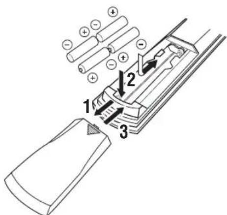
1 Press the part and slide the battery compartment cover off.
2 Insert four supplied batteries (AAA, R03, UM-4) according to the polarity markings (+ / -) on the inside of the battery compartment.
3 Slide the cover back until it snaps into place.
Notes on batteries
- Change all of the batteries if you notice the following conditions; the operation range of the remote control decreases, the indicator does not flash or its light becomes dim.
- Do not use old batteries together with new ones.
- Do not use different types of batteries (such as alkaline and manganese batteries) together. Read the packaging carefully as these different types of batteries may have the same shape and color.
- If the batteries have leaked, dispose of them immediately. Avoid touching the leaked material or letting it come into contact with clothing, etc. Clean the battery compartment thoroughly before installing new batteries.
- Do not throw away batteries with general house waste; dispose of them correctly in accordance with your local regulations.
If the remote control is without batteries for more than 2 minutes, or if exhausted batteries remain in the remote control, the contents of the memory may be cleared. When the memory is cleared, insert new batteries, set up the remote control code and program any acquired functions that may have been cleared.
CONTROLS AND FUNCTIONS
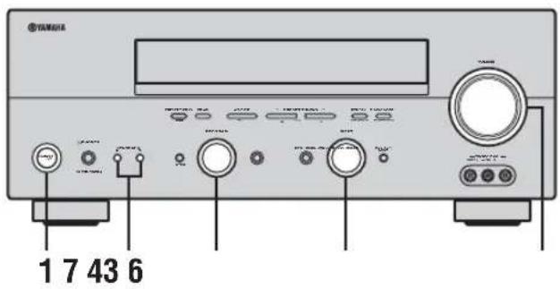
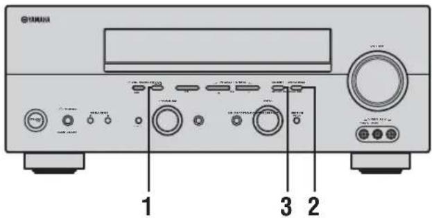
Front panel
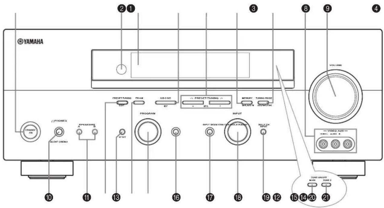
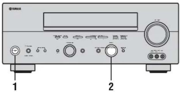
1 STANDBY/ON
Turns on this unit or sets it to the standby mode. When you turn on this unit, you will hear a click and there will be a 4 to 5-second delay before this unit can reproduce sound.
Note
In standby mode, this unit consumes a small amount of power in order to receive infrared-signals from the remote control.
2 Remote control sensor
Receives signals from the remote control.
3 Front panel display
Shows information about the operational status of this unit.
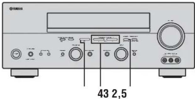
4 A/B/C/D/E, NEXT
Selects one of the 5 preset station groups (A to E) when the unit is in tuner mode.
Selects the speaker channel to be adjusted when the unit is not in tuner mode.
5 PRESET/TUNING | /h, LEVEL -/+
Selects preset station number 1 to 8 when the colon (:) is displayed next to the band indication in the front panel display when the unit is in tuner mode. Selects the tuning frequency when the colon (:) is not displayed.
Adjusts the level of the speaker channel selected using A/B/C/D/E (NEXT) when the unit is not in tuner mode.
6 MEMORY (MAN'L/AUTO FM)
Stores a station in the memory. Hold down this button for more than 3 seconds to start automatic preset tuning.
7 TUNING MODE (AUTO/MAN'L MONO)
Switches between automatic tuning (AUTO indicator on) and manual tuning (AUTO indicator off).
8 VIDEO AUX jacks
Input audio and video signals from a portable external source such as a game console. To reproduce source signals from these jacks, select V-AUX as the input source.
9 VOLUME
Controls the output level of all audio channels.
This does not affect the REC OUT level.
0 PHONES (SILENT CINEMA) jack
Outputs audio signals for private listening with headphones. When you connect headphones, no signals are output to the OUTPUT jacks or to the speakers.
All Dolby Digital and DTS audio signals are mixed down to the left and right headphone channels.
A SPEAKERS A/B
Turns on or off the set of front speakers connected to the A and/or B terminals on the rear panel each time the corresponding button is pressed.
B PRESET/TUNING (EDIT)
Switches the function of PRESET/TUNING I / h (LEVEL -/+ ) between selecting preset station numbers and tuning.
C STRAIGHT (EFFECT)
Switches the sound fields off or on. When STRAIGHT is selected, input signals (2-channel or multi-channel) are output directly from their respective speakers without effect processing.
D FM/AM
Switches the reception band when the unit is in tuner mode.
E PROGRAM
Use to select sound field programs or adjust the bass/treble balance (in conjunction with TONE CONTROL).
F TONE CONTROL
Use to adjust the bass/treble balance for the front left and right speakers (see page 26).
G INPUT MODE
Sets the priority (AUTO, DTS, ANALOG) for the type of signals received when one component is connected to two or more of this unit's input jacks (see page 32).
H INPUT selector
Selects the input source you want to listen to or watch.
I MULTI CH INPUT
Selects the source connected to the MULTI CH INPUT jacks. When selected, the MULTI CH INPUT source takes priority over the source selected with INPUT (or the input selector buttons on the remote control).
J MAIN
Switches this unit's operation to control the component in the main room (see page 61).
K ZONE 2
Switches this unit's operation to control the component in the second room (Zone 2) (see page 61).
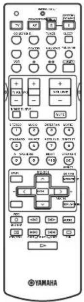
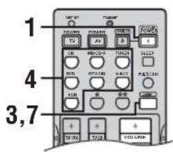
Remote control
This section describes the function of each control on the remote control used to control this unit. To operate other components, see “REMOTE CONTROL FEATURES” on page 57.
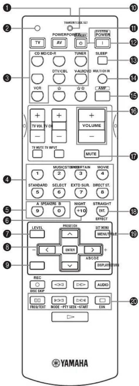
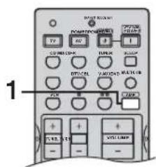
1 Infrared window
Outputs infrared control signals. Aim this window at the component you want to operate.
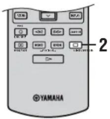
2 CODE SET
Use to set up remote control codes (see page 58).
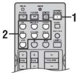
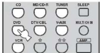
3 Input selector buttons
Select the input source and change the control area.
4 Sound field program/numeric buttons
Use to select sound field programs.
Use numbers 1 through 8 to select preset stations when the unit is in tuner mode.
Use SELECT to playback 2-channel sources in surround (see page 29).
Use EXTD SUR. to switch between 5.1 or 6.1-channel playback of multi-channel software (see page 28).
Use DIRECT ST. to playback 2-channel sources in high fidelity sound (see page 30).
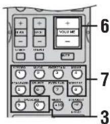
5 SPEAKERS A/B
Use to turn on or off the set of front speakers connected to the A and/or B terminals on the rear panel each time the corresponding button is pressed.
6 NIGHT
Turns on or off the night listening modes (page 30).
7 LEVEL
Selects the speaker channel to be adjusted and sets the level.
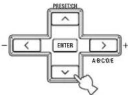
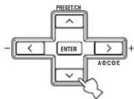
8 Cursor buttons u /d /j /i /ENTER
Use to select and adjust sound field program parameters or SET MENU items.
Press i to select a preset station group (A to E) when the unit is in tuner mode.
Press u /d to select a preset station number (1 to 8) when the unit is in tuner mode.
9 RETURN
Returns to the previous menu level when adjusting the SET MENU parameters.
0 TRANSMIT indicator
Flashes while the remote control is sending signals.
A STANDBY
Sets this unit in the standby mode.
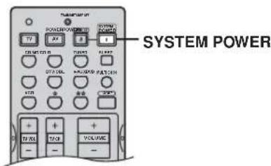
B SYSTEM POWER
Turns on the power of this unit.
C SLEEP
Sets the sleep timer.
D MULTI CH IN
Selects multi-channel input when using an external decoder (etc.).
E AMP
Selects the AMP mode. You must select the AMP mode to control the main unit.
F VOLUME +/-
Increases or decreases the volume level.
G MUTE
Mutes the sound. Press again to restore the audio output to the previous volume level.
H STRAIGHT (EFFECT)
Switches the sound fields off or on. When STRAIGHT is selected, input signals (2-channel or multi-channel) are output directly from their respective speakers without effect processing.
I SET MENU
Activates the SET MENU function.
J Radio Data System tuning buttons
FREQ/TEXT
Press this button when the unit is receiving a Radio Data System station to cycle the display between the PS mode, PTY mode, RT mode, CT mode (if the station offers those Radio Data System data services) and/or the frequency display (see page 39).
PTY SEEK MODE
Press this button to set the unit to the PTY SEEK mode (see page 40).
PTY SEEK START
Press this button to begin searching for a station after the desired program type has been selected in the PTY SEEK mode (see page 40).
EON
Press this button to select a radio program type (NEWS, INFO, AFFAIRS, SPORT) to tune in automatically (see page 41).
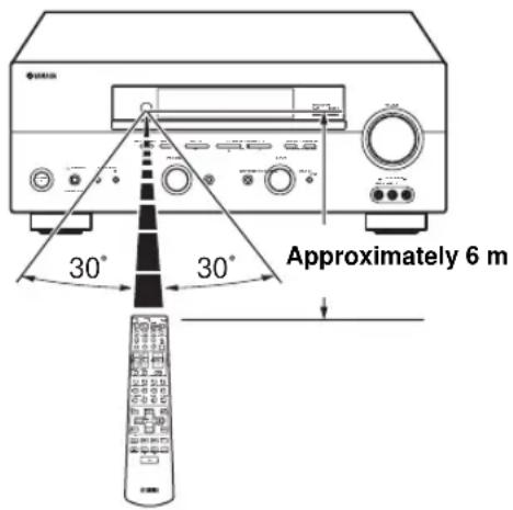
Using the remote control
The remote control transmits a directional infrared beam. Be sure to aim the remote control directly at the remote control sensor on the main unit during operation.
■ Handling the remote control
- Do not spill water or other liquids on the remote control.
- Do not drop the remote control.
- Do not leave or store the remote control in the following types of conditions:
- places of high humidity, such as near a bath
- places of high temperatures, such as near a heater or stove
- extremely low temperatures
- dusty places
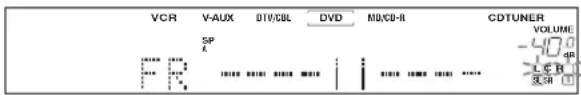
Front panel display
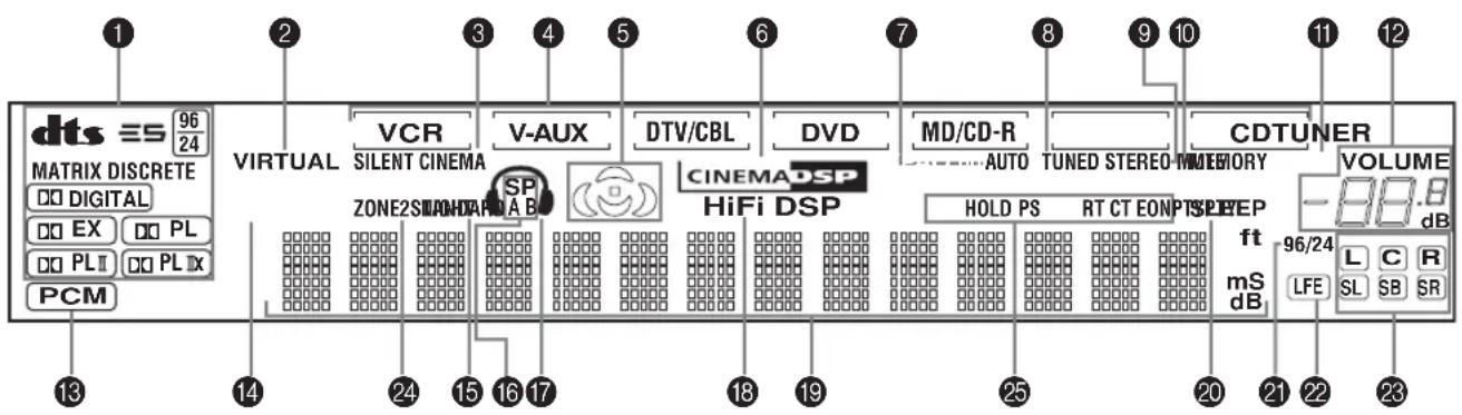
1 Decoder indicators
When any of this unit's decoders function, the respective indicator lights up.
2 VIRTUAL indicator
Lights up when Virtual CINEMA DSP is active (see page 31).
3 SILENT CINEMA indicator
Lights up when headphones are connected and a sound field program is selected (see page 26).
4 Input source indicators
A cursor lights to show the current input source.
5 Sound field indicators
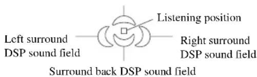
Light to indicate the active DSP sound fields.
Presence DSP sound field
6 CINEMA DSP indicator
Lights up when you select a CINEMA DSP sound field program.
7 AUTO indicator
Lights up to indicate that automatic tuning is possible.
8 TUNED indicator
Lights up when this unit is tuned into a station.
9 STEREO indicator
Lights up when this unit is receiving a strong signal for an FM stereo broadcast while the AUTO indicator is lit.
0 MEMORY indicator
Flashes to show that a station can be stored.
A MUTE indicator
Flashes while the MUTE function is on.
B VOLUME level indication
Indicates the current volume level.
c PCM indicator
Lights up when this unit is reproducing PCM (Pulse Code Modulation) digital audio signals.
D STANDARD indicator
Lights up when Surround Standard or Surround Enhanced is selected (see page 29).
E NIGHT indicator
Lights up when you select night listening mode.
F SP A B indicators
Light up according to the set of front speakers selected. Both indicators light up when both sets of speakers are selected.
G Headphones indicator
Lights up when headphones are connected.
H HiFi DSP indicator
Lights up when you select a HiFi DSP sound field program.
I Multi-information display
Shows the current sound field program name and other information when adjusting or changing settings.
J SLEEP indicator
Lights up while the sleep timer is on.
K 96/24 indicator
Lights up when a DTS 96/24 signal is input to this unit.
L LFE indicator
Lights up when the input signal contains the LFE signal.
M Input channel indicators/speaker indicators
Indicate the channel components of the current digital input signal.
Indicate the number of speakers connected in SPEAKERS (page 23), or indicate the channel being adjusted in SP LEVEL (page 51).
N ZONE 2 indicator
Lights up when Zone 2 power is on.
○ Radio Data System indicators
The name(s) of the Radio Data System data offered by the currently received Radio Data System station light(s) up.
EON lights up when an Radio Data System station that offers the EON data service is being received.
PTY HOLD lights up while searching for stations in the PTY SEEK mode.
Rear panel
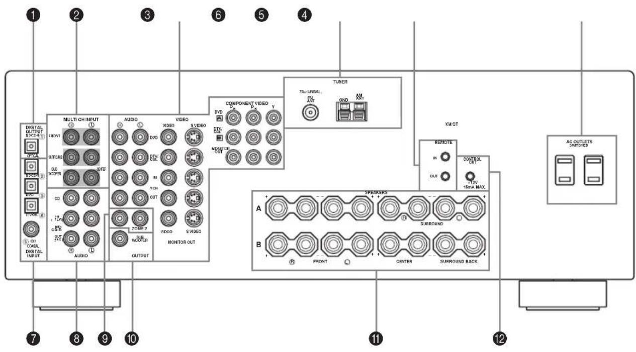
1 DIGITAL OUTPUT jack
See page 18 for details.
2 MULTI CH INPUT jacks
See page 16 for connection information.
3 Video component jacks
See pages 15 and 17 for connection information.
4 Antenna terminals
See page 19 for connection information.
5 REMOTE IN/OUT jacks
See page 61 for details.
6 AC OUTLET(S)
Use to supply power to your other A/V components (see page 20).
7 DIGITAL INPUT jack
See pages 15, 17 and 18 for details.
8 Audio component jacks
See page 18 for connection information.
9 ZONE 2 OUTPUT jacks
These jacks output analog signals only. See page 61 for details.
0 SUBWOOFER OUTPUT jack
See page 13 for connection information.
A Speaker terminals
See page 13 for connection information.
B CONTROL OUT jack
This is a control expansion terminal for commercial use.
SPEAKER SETUP
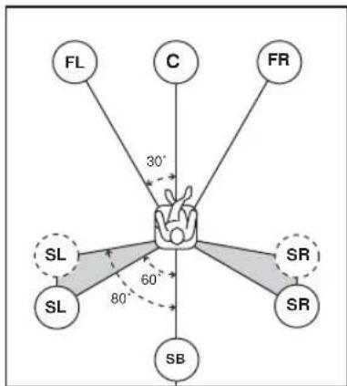
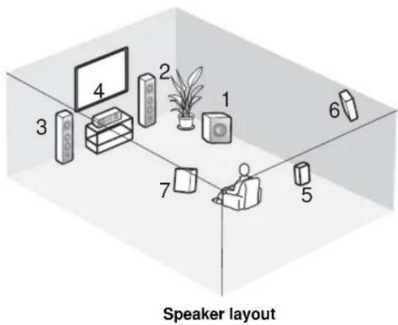
Speaker placement
The speaker layout below shows the standard ITU-R* speaker setting. You can use it to enjoy CINEMA DSP and multi-channel audio sources.
* ITU-R is the radio communication sector of the ITU (International Telecommunication Union).
flowchart
graph TD
    FL["FL"] -->|30°| Center((Center))
    C["C"] -->|30°| Center
    FR["FR"] -->|30°| Center
    SL["SL"] -->|60°| Center
    SR["SR"] -->|60°| Center
    SB["SB"] -->|80°| Center
    Center -->|30°| Subgraph Left
    Center -->|60°| Subgraph Right
    Center -->|80°| Subgraph Bottom
    Center --> SL["SL"]
    Center --> SR["SR"]
Front speakers (FR and FL)
The front speakers are used for the main source sound plus effect sounds. Place these speakers an equal distance from the ideal listening position. The distance of each speaker from each side of the video monitor should be the same.
Center speaker (C)
The center speaker is for the center channel sounds (dialog, vocals, etc.). If for some reason it is not practical to use a center speaker, you can do without it. Best results, however, are obtained with the full system. Align the front face of the center speaker with the front face of your video monitor. Place the speaker centrally between the front speakers and as close to the monitor as possible, such as directly over or under it.
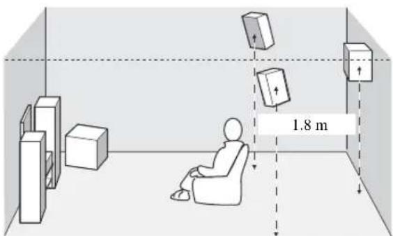
Surround speakers (SR and SL)
The surround speakers are used for effect and surround sounds. Place these speakers behind your listening position, facing slightly inwards, about 1.8 m above the floor.
Surround back speaker (SB)
The surround back speaker supplements the surround speakers and provides for more realistic front-to-back transitions. Place this speaker directly behind the listening position and at the same height as the surround speakers.
Subwoofer
The use of a subwoofer, such as the YAMAHA Active Servo Processing Subwoofer System, is effective not only for reinforcing bass frequencies from any or all channels, but also for high fidelity reproduction of the LFE (low-frequency effect) channel included in Dolby Digital and DTS software. The position of the subwoofer is not so critical, because low bass sounds are not highly directional. But it is better to place the subwoofer near the front speakers. Turn it slightly toward the center of the room to reduce wall reflections.
Speaker connections
Be sure to connect the left channel (L), right channel (R), “+” (red) and “-” (black) properly. If the connections are faulty, no sound will be heard from the speakers, and if the polarity of the speaker connections is incorrect, the sound will be unnatural and lack bass.
CAUTION
- If you will use 4 or 6 ohm speakers, be sure to set this unit's speaker impedance setting to 4 ohms before using (see page 21).
- Before connecting the speakers, make sure that the power of this unit is off.
- Do not let the bare speaker wires touch each other or do not let them touch any metal part of this unit. This could damage this unit and/or speakers.
- Use magnetically shielded speakers. If this type of speakers still creates the interference with the monitor, place the speakers away from the monitor.
A speaker cord is actually a pair of insulated cables running side by side. One cable is colored or shaped differently, perhaps with a stripe, groove or ridges. Connect the striped (grooved, etc.) cable to the “+” (red) terminals on this unit and your speaker. Connect the plain cable to the “−” (black) terminals.
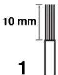
2

1 Remove approximately 10 mm of insulation from the end of each speaker cable.
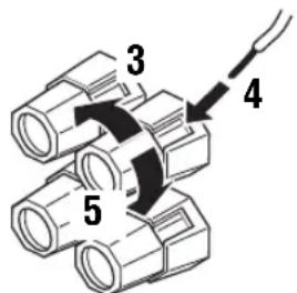
2 Twist the exposed wires of the cable together to prevent short circuits.
3 Unscrew the knob.
4 Insert one bare wire into the hole in the side of each terminal.
5 Tighten the knob to secure the wire.
Red: positive (+) Black: negative (−)
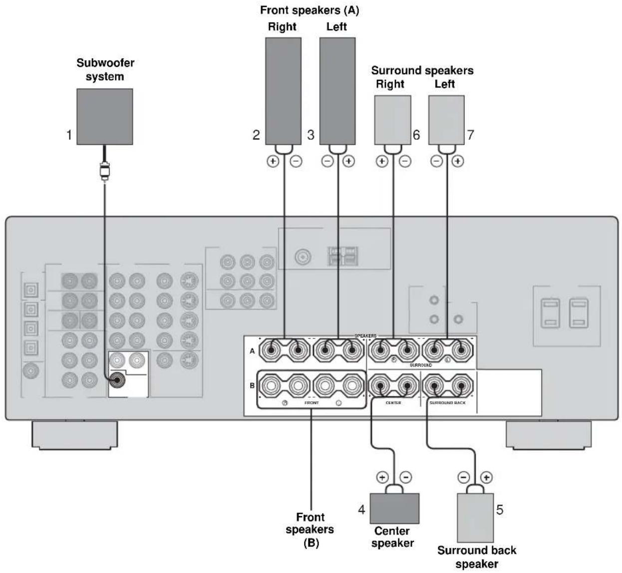
■ FRONT terminals
Connect one or two speaker systems (2, 3) to these terminals. If you use only one speaker system, connect it to the FRONT A or B terminals.
■ CENTER terminals
Connect a center speaker (4) to these terminals.
■ SURROUND terminals
Connect surround speakers (6, 7) to these terminals.
■ SUBWOOFER jack
Connect a subwoofer with built-in amplifier (1), such as the YAMAHA Active Servo Processing Subwoofer System, to this jack.
Connect a surround back speaker (5) to these terminals.
CONNECTIONS
Before connecting components
CAUTION
Do not connect this unit or other components to the mains power until all connections between components are complete.
■ Cable indications
For analog signals
| left analog cables | L |
| right analog cables | R |
| or digital signals | |
| optical cables | O |
| coaxial cables | C |
| or video signals | |
| video cables | V |
| S-video cables | S |
| component video cables | PbPbY |
■ Analog jacks
You can input analog signals from audio components by connecting audio pin cable to the analog jacks on this unit. Connect red plugs to the right jacks and white plugs to the left jacks.
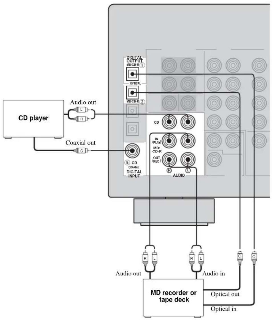
■ Digital jacks
This unit has digital jacks for direct transmission of digital signals through either coaxial or fiber optic cables. You can use the digital jacks to input PCM, Dolby Digital and DTS bitstreams. When you connect components to both the COAXIAL and OPTICAL jacks, priority is given to the input signals from the COAXIAL jack. All digital input jacks are compatible with 96-kHz sampling digital signals.
Note
This unit handles digital and analog signals independently. Thus audio signals input to the analog jacks are only output to the analog OUT (REC) jacks. Likewise audio signals input to the digital (OPTICAL or COAXIAL) jacks are only output to the DIGITAL OUTPUT jack.
Dust protection cap
Pull out the cap from the optical jack before you connect the fiber optic cable. Do not discard the cap. When you are not using the optical jack, be sure to put the cap back in place. This cap protects the jack from dust.
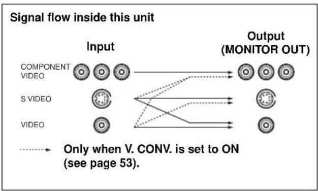
■ Video jacks
This unit has three types of video jacks. Connection depends on the availability of input jacks on your monitor. The signals input through the S VIDEO jacks on this unit are automatically converted for output through the VIDEO jacks. When V. CONV. is set to ON (see page 53), signals input through the VIDEO jacks can be output through the S VIDEO and COMPONENT VIDEO jacks.


VIDEO jacks
For conventional composite video signals.
S VIDEO jacks
For S-video signals, separated into luminance (Y) and color (C) video signals to achieve high-quality color reproduction.
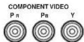
COMPONENT VIDEO jacks
For component signals, separated into luminance (Y) and color difference (P_B,P_R) to provide the best quality in picture reproduction.
flowchart
graph LR
    A["COMPONENT VIDEO"] --> B["OUTPUT (MONITOR OUT)"]
    C["S VIDEO"] --> B
    D["VIDEO"] --> B
    E["..."] --> B
    F["..."] --> B
    G["..."] --> B
    H["..."] --> B
    I["..."] --> B
    J["..."] --> B
    K["..."] --> B
    L["..."] --> B
    M["..."] --> B
    N["..."] --> B
    O["..."] --> B
    P["..."] --> B
    Q["..."] --> B
    R["..."] --> B
    S["..."] --> B
    T["..."] --> B
    U["..."] --> B
    V["..."] --> B
    W["..."] --> B
    X["..."] --> B
    Y["..."] --> B
    Z["..."] --> B
    AA["..."] --> B
    AB["..."] --> B
    AC["..."] --> B
    AD["..."] --> B
    AE["..."] --> B
    AF["..."] --> B
    AG["..."] --> B
    AH["..."] --> B
    AI["..."] --> B
    AJ["..."] --> B
    AK["..."] --> B
    AL["..."] --> B
    AM["..."] --> B
    AN["..."] --> B
    AO["..."] --> B
    AP["..."] --> B
    AQ["..."] --> B
    AR["..."] --> B
    AS["..."] --> B
    AT["..."] --> B
    AU["..."] --> B
    AV["..."] --> B
    AW["..."] --> B
    AX["..."] --> B
    AY["COMPONENT VIDEO"] --> AZ["OUTPUT (MONITOR OUT)"]
    C["S VIDEO"] --> BA["OUTPUT (MONITOR OUT)"]
    V["VIDEO"] --> BA
    AB["..."] --> BA
    AD["..."] --> BA
    AE["..."] --> BA
    AF["..."] --> BA
    AG["..."] --> BA
    AH["..."] --> BA
Note
When signals are input through both the S VIDEO and VIDEO jacks, signals input through the S VIDEO jack have priority.
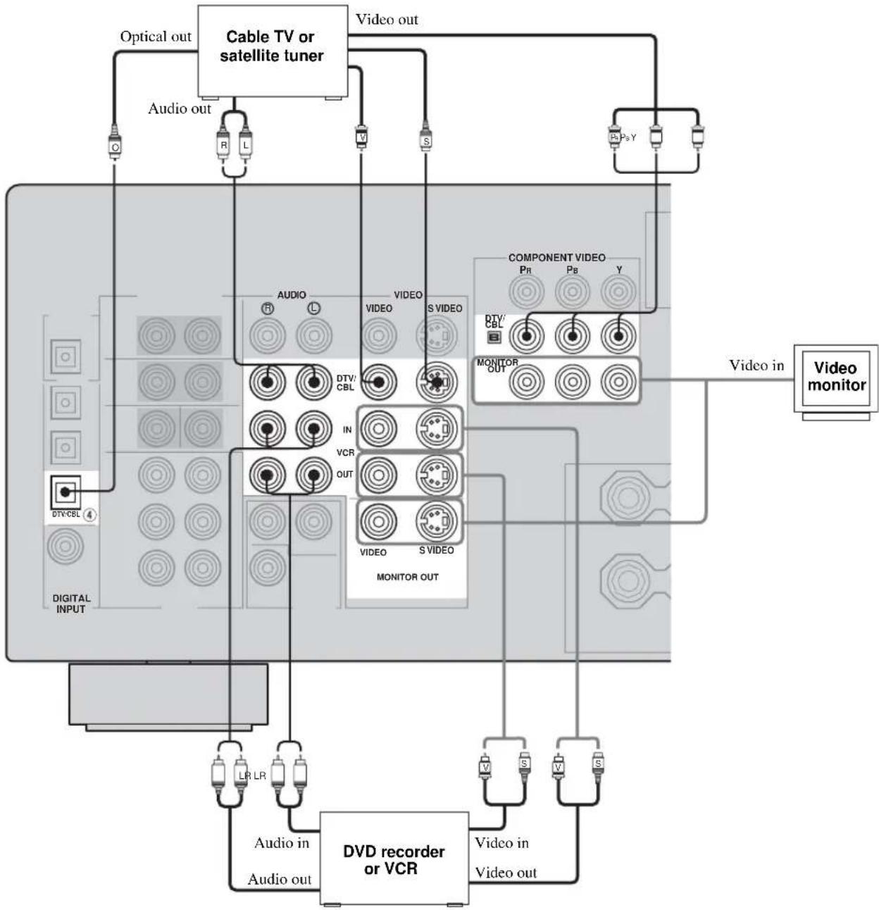
Connecting video components
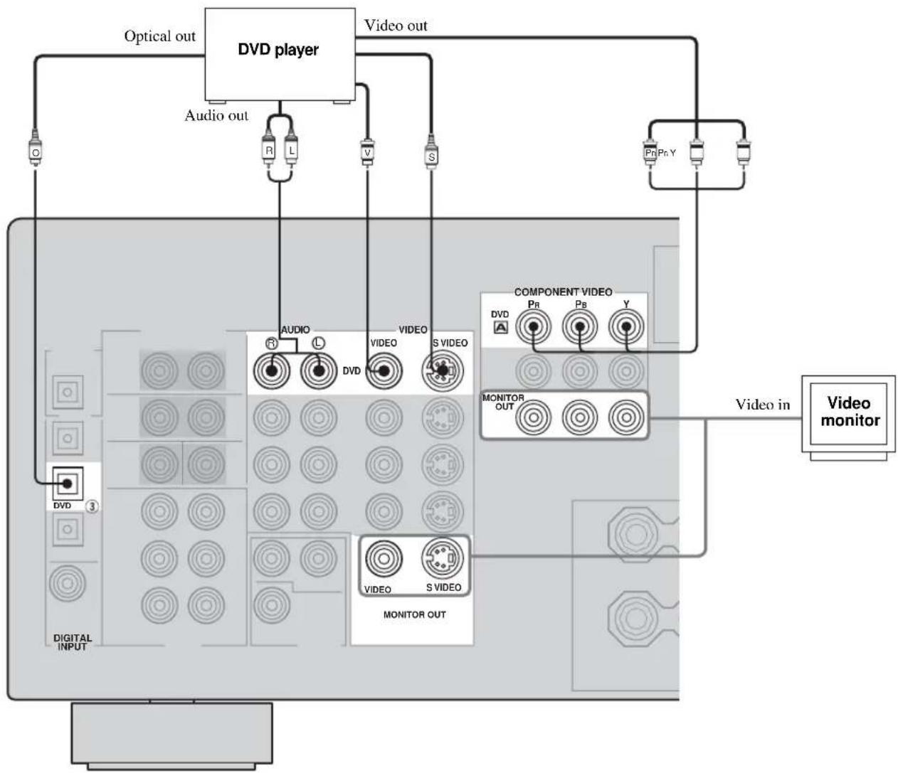
■ Connections for DVD playback
Note
Be sure to connect your video source components in the same way you connect your video monitor to this unit if V. CONV. (see page 53) is set to OFF. For example, if you connect your video monitor to this unit using a VIDEO connection, connect your video source components to this unit using the VIDEO connections. (Even when V. CONV. is set to OFF, S-video signals input from your video source component are automatically converted to composite signals in this unit.)
flowchart
graph TD
    A["Optical out"] --> B["DVD player"]
    C["Audio out"] --> B
    D["Video out"] --> B
    B --> E["Component Video"]
    E --> F["Monitor OUT"]
    F --> G["Video monitor"]
    H["Digital INPUT"] --> I["VIDEO OUT"]
    J["DV3"] --> K["VIDEO"]
    L["DV"] --> M["VIDEO"]
    N["Pr"] --> O["Pr"]
    P["Pr,Y"] --> Q["Pr,Y"]
    R["3"] --> S["3"]
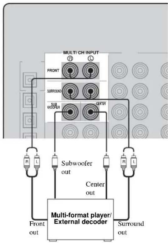
■ Connecting to the MULTI CH INPUT jacks
This unit is equipped with 6 additional input jacks (left and right FRONT, CENTER, left and right SURROUND and SUBWOOFER) for discrete multi-channel input from a multi-format player, external decoder, sound processor or pre-amplifier.
Connect the output jacks on your multi-format player or external decoder to the MULTI CH INPUT jacks. Be sure to match the left and right outputs to the left and right input jacks for the front and surround channels.
flowchart
graph TD
    A["Multi-format player/External decoder"] --> B["Front out"]
    A --> C["Subwoofer out"]
    A --> D["Center out"]
    A --> E["Surround out"]
    A --> F["R L"]
    A --> G["R L"]
    A --> H["FRONT"]
    A --> I["SURROUND"]
    A --> J["SUBWOOFER"]
    A --> K["CENTER"]
    style A fill:#f9f,stroke:#333
    style B fill:#ccf,stroke:#333
    style C fill:#ccf,stroke:#333
    style D fill:#ccf,stroke:#333
    style E fill:#ccf,stroke:#333
    style F fill:#ccf,stroke:#333
    style G fill:#ccf,stroke:#333
    style H fill:#ccf,stroke:#333
    style I fill:#ccf,stroke:#333
    style J fill:#ccf,stroke:#333
    style K fill:#ccf,stroke:#333
Notes
- When you select MULTI CH INPUT as the input source, this unit automatically turns off the digital sound field processor, and you cannot select sound field programs.
- This unit does not redirect signals input to the MULTI CH INPUT jacks to accommodate for missing speakers. We recommend that you connect at least a 5.1-channel speaker system before using this feature.
- When headphones are used, only front left and right channels are output.
■ Connections for other video components
Notes
- Be sure to connect your video source components in the same way you connect your video monitor to this unit if V. CONV. (see page 53) is set to OFF. For example, if you connect your video monitor to this unit using a VIDEO connection, connect your video source components to this unit using the VIDEO connections. (Even when V. CONV. is set to OFF, S-video signals input from your video source component are automatically converted to composite signals in this unit.)
- Converted video signals are only output to the MONITOR OUT jacks. When recording, you must make the same type of video connections (i.e., S-video) between each component.
flowchart
graph TD
    A["Cable TV or satellite tuner"] -->|Optical out| B["Audio out"]
    A -->|Video out| C["Component Video"]
    A --> D["Monitor Out"]
    A --> E["DVD recorder or VCR"]
    E --> F["Video in Video out"]
    A --> G["Digital Input"]
    G --> H["Audio in Audio out"]
    H --> I["LR LR"]
    I --> J["Video in Video out"]
    A --> K["Video monitor"]
    K --> L["Video in"]
    style A fill:#f9f,stroke:#333
    style B fill:#ccf,stroke:#333
    style C fill:#cfc,stroke:#333
    style D fill:#fcc,stroke:#333
    style E fill:#cff,stroke:#333
    style F fill:#ffc,stroke:#333
    style G fill:#cfc,stroke:#333
    style H fill:#fcc,stroke:#333
    style I fill:#cfc,stroke:#333
    style J fill:#cfc,stroke:#333
    style K fill:#cfc,stroke:#333
    style L fill:#cfc,stroke:#333
    style_M["Digital Input"] --> N["Audio in Audio out"]
    N --> O["LR LR"]
    O --> P["Video in Video out"]
    P --> Q["Video monitor"]
    Q --> R["Video in"]
    style A fill:#f9f,stroke:#333
    style B fill:#ccf,stroke:#333
    style C fill:#cfc,stroke:#333
    style D fill:#fcc,stroke:#333
    style E fill:#cfc,stroke:#333
    style F fill:#cfc,stroke:#333
    style G fill:#cfc,stroke:#333
    style H fill:#cfc,stroke:#333
    style I fill:#cfc,stroke:#333
    style J fill:#cfc,stroke:#333
    style K fill:#cfc,stroke:#333
    style L fill:#cfc,stroke:#333
    style M fill:#cfc,stroke:#333
    style N fill:#cfc,stroke:#333
    style O fill:#cfc,stroke:#333
    style P fill:#cfc,stroke:#333
    style Q fill:#cfc,stroke:#333
    style R fill:#cfc,stroke:#333
    style S fill:#cfc,stroke:#333
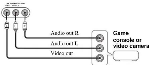
■ VIDEO AUX jacks (on the front panel)
Use these jacks to connect any video source, such as a game console or video camera, to this unit.
Connecting audio components
■ Connections for audio components
flowchart
graph TD
    A["CD player"] -->|Audio out L R| B["Coaxial out C"]
    B --> C["Digital OUTPUT MD-CD-R ①"]
    C --> D["OPTICAL"]
    C --> E["MD-CD-R ②"]
    E --> F["CD"]
    F --> G["IN (PLAY) MD/CD-R OUT (REC)"]
    G --> H["AUDIO"]
    H --> I["Audio in"]
    I --> J["MD recorder or tape deck"]
    J --> K["Audio out"]
    J --> L["Audio in"]
    J --> M["Optical out"]
    J --> N["Optical in"]
Connecting the FM and AM antennas
Both FM and AM indoor antennas are included with this unit. In general, these antennas should provide sufficient signal strength. Connect each antenna correctly to the designated terminals.
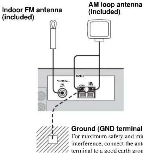
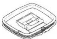
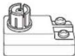
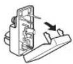
■ Connecting the AM loop antenna
1 Set up the AM loop antenna.
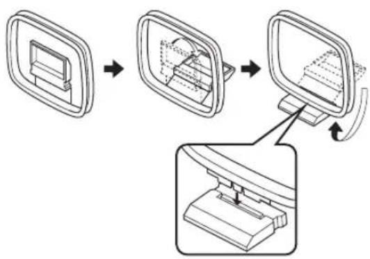
flowchart
graph TD
    A["Component placement"] --> B["Assembly"]
    B --> C["Final assembly with mounting bracket"]
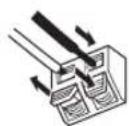
2 Press and hold the tab to insert the AM loop antenna lead wires into the AM ANT and GND terminals.
3 Orient the AM loop antenna for the best reception.

Notes
- The AM loop antenna should be placed away from this unit.
- The AM loop antenna should always be connected, even if an outdoor AM antenna is connected to this unit.
- A properly installed outdoor antenna provides clearer reception than an indoor one. If you experience poor reception quality, an outdoor antenna may improve the quality. Consult the nearest authorized YAMAHA dealer or service center about outdoor antennas.
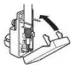
■ Connecting the 75-ohm/300-ohm antenna adapter (U.K. model only)
1 Open the cover of the included 75-ohm/300-ohm antenna adapter.
2 Cut the external sleeve of the 75-ohm coaxial cable and prepare it for connection.
11 8 6

Unit: mm
3 Cut the lead wire and remove it.
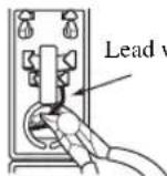
4 Insert the cable wire into the slot, and clamp it with pliers.
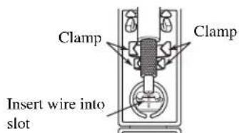
5 Snap the cover into place.
Connecting the power supply cord
■ Connecting the AC power cord
Plug the power cord into an AC wall outlet.
■ AC OUTLET(S) (SWITCHED)
U.K. model 1 outlet
Other models ......2 outlets
Use these outlets to connect the power cords from your other components to this unit. Power to the AC OUTLET(S) is controlled by this unit's STANDBY/ON (or SYSTEM POWER and STANDBY). The outlet(s) supply power to any connected component whenever this unit is turned on. For information on the maximum power (total power consumption of components), see “SPECIFICATIONS” on page 76.
■ Memory back-up
The memory back-up circuit prevents the stored data from being lost even if this unit is in the standby mode.
However if the power cord is disconnected from the AC wall outlet, or the power supply is cut for more than one week, the stored data will be lost.
Speaker impedance setting
CAUTION
If you are using 4 or 6 ohm speakers, set the impedance to 4 or 6 ohms as follows before turning on the power.
Be sure this unit is in the standby mode.
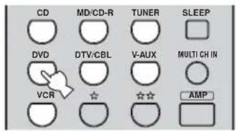
1 Turn off the power to this unit, and while holding down STRAIGHT (EFFECT), press STANDBY/ON.
This unit turns on, and the ADVANCED SETUP menu appears in the front panel display.
STRAIGHT

While holding down, press

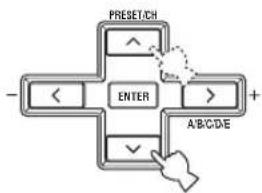
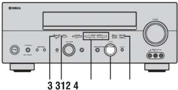
2 Rotate PROGRAM to move through the menu and select "SP IMP.".
PROGRAM

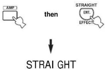
3 Press STRAIGHT (EFFECT) repeatedly to select "4 Ω MIN".
STRAIGHT

4 Press STANDBY/ON to turn off the power.

The setting you made is reflected the next time this unit's power is turned on.
Turning on the power
When all connections are complete, turn on the power of this unit.
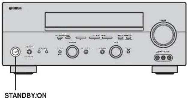
Press STANDBY/ON (or SYSTEM POWER on the remote control) to turn on the power of this unit.

Front panel
or

Remote control
BASIC SETUP
The basic setup feature is a useful way to set up your system quickly and with minimal effort.
y
- If you wish to configure the unit manually using more precise adjustments, use the detailed parameters in SOUND MENU (page 50) instead of using BASIC SETUP.
- Altering any parameters in BASIC SETUP will reset all parameters in SOUND MENU.
- Initial settings are indicated in bold for each parameter.
Using the BASIC SETUP menu
Before you begin:
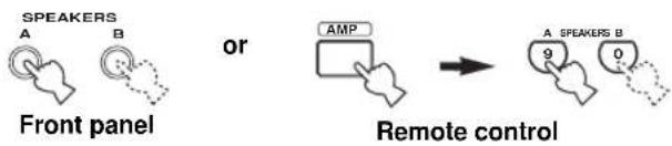
- Press SPEAKERS A or B on the front panel (or press AMP to select the AMP mode, then press SPEAKERS A or B on the remote control) to select the front speakers you want to use.
- Make sure you disconnect your headphones from this unit.
"BASIC SETUP" appears in the front panel display.


BASIC SETUP
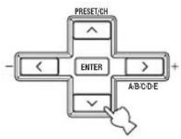
3 Press ENTER to enter BASIC SETUP.
flowchart
graph TD
    A["ENTER"] --> B["PRESET/CH"]
    A --> C["A/B/C/D/E"]
    A --> D["+"]
    A --> E["✓"]
    A --> F["<"]
    A --> G["<"]
The ROOM parameter appears in the front panel display.
4 Press j / i to select the desired setting.
ROOM: S M >L
Select the size of the room you have installed your speakers in. In general, the room sizes are defined as follows:
S (small) 3.6 x 2.8m, 10m ^2
M (medium) 4.8 x 4.0m, 20m²
L (large) 6.3 x 5.0m, 30m 2
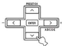
5 Press d to display the SUBWOOFER parameter.
flowchart
graph TD
    A["ENTER"] --> B["PRESET/CH"]
    A --> C["A/B/C/D/E"]
    A --> D["+"]
    A --> E["✓"]
    A --> F["<"]
    A --> G["<"]
6 Press j / i to select the desired setting.
SUBWOOFER = YES
YES If you have a subwoofer in your system. NONE If you do not have a subwoofer in your system.
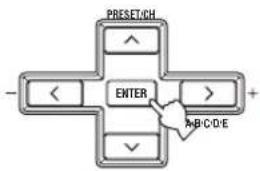
7 Press d to display the SPEAKERS parameter.
flowchart
graph TD
    A["PRESET/CH"] --> B["ENTER"]
    B --> C["+"]
    B --> D["✓"]
    D --> E["ABC/D/E"]
    B --> F["<"]
    B --> G["<"]
8 Press j /i to select the number of speakers you connected.
$$ \text { SPEAKERS } = \text { 6s.pk } $$
| Choices Display Speakers | ||
| 2spk | Front L/R | |
| 3spk | Front L/R, Center | |
| 4spk | Front L/R, Surround L/R | |
| 5spk | Front L/R, Center, Surround L/R | |
| 6spk | Front L/R, Center, Surround L/R, Surround back | |
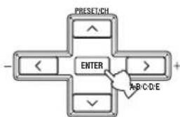
9 Press d to display SET/CANCEL.
flowchart
graph TD
    A["PRESET/CH"] --> B["ENTER"]
    C["-"] --> B
    D["+"] --> B
    E["A/B/C/D-E"] --> B
    F["✓"] --> B
10 Press j / i to select the desired setting.
SET CANCEL
SET To apply the settings you chose in steps 4 through 8.
CANCEL To cancel the setup without making any changes.
11 Press ENTER to confirm your selection.
flowchart
graph TD
    A["ENTER"] --> B["PRESET/CH"]
    A --> C["A/B/C/D/E"]
    A --> D["+"]
    A --> E["<"]
    A --> F[">"]
If you selected SET, you hear a test tone from each speaker in turn. "CHECK:TestTone" appears in the front panel display for a few seconds, then "CHECK OK?".
CHECK: Test Tone
↓ CHECK OK? YES
12 Press j / i to select the desired setting.
CHECK OK? YES
YES To complete the setup process if the test tone levels from each speaker were satisfactory.
NO To proceed to the SP LEVEL speaker level adjustment menu to balance the level of each speaker.
13 Press ENTER to confirm your selection.
flowchart
graph TD
    A["ENTER"] --> B["PRESET/CH"]
    A --> C["A/B/C/D/E"]
    A --> D["+"]
    A --> E["↓"]
    A --> F["<"]
If you selected NO in step 12, the front speaker level adjustment display appears in the front panel display.
■ To balance the speaker levels
Perform the following steps after step 13 (see page 23).
The unit outputs the test tone from the selected speaker and the left front (or left surround) speaker in turn. The indicator of the speaker currently outputting the test tone flashes in the front panel display.
14 Press d /u to select a speaker, then use j /i to adjust the balance.
The control range is from +10 dB to -10 dB.
$$ F R - - - - | | - - - - $$
Adjusts the balance between the front left and right speakers.
$$ C - - - - | | - - - - $$
Adjusts the balance between the front left and center speakers.
$$ \mathrm{SL} - - - - | | - - - - $$
Adjusts the balance between the front left and surround left speakers.
$$ \mathrm{SB} - - - - | | - - - - $$
Adjusts the balance between the surround left and surround back speakers.
$$ \mathrm{SR} - - - - | | - - - - $$
Adjusts the balance between the surround left and surround right speakers.
$$ \text { SWFR } - - - - | | - - - - $$
Adjusts the balance between the front left speaker and the subwoofer.
15 Press SET MENU to exit after balancing the speakers.
Memory back-up
The memory back-up circuit prevents the stored data from being lost even if this unit is in the standby mode. However, if the power cord is disconnected from the AC outlet, or the power supply is cut for more than one week, the stored data will be lost. If so, adjust the items again.
PLAYBACK
Basic operations
1 Press STANDBY/ON (or SYSTEM POWER on the remote control) to turn on the power.

Front panel
or

Remote control
2 Turn on the video monitor connected to this unit.
3 Press SPEAKERS A or B (or press AMP to select the AMP mode, then press SPEAKERS A or B on the remote control).
Each press turns the respective speakers on or off.
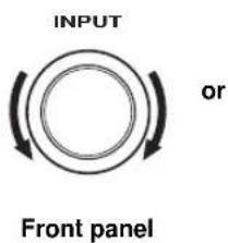
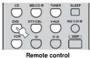
4 Select the input source.
Use INPUT (or press one of the input selector buttons on the remote control) to select the input you desire.
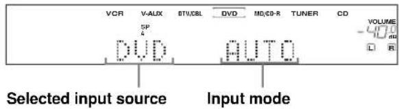
The current input source name and input mode appear in the front panel display for a few seconds.
5 Start playback or select a broadcast station on the source component.
Refer to the operating instructions for the component.
6 Adjust the volume to the desired output level.
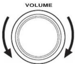
Front panel
or
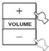
Remote control
7 Select a sound field program if desired.
Rotate PROGRAM (or press AMP to select the AMP mode, then press one of the sound field program buttons on the remote control) to select a sound field program. (See page 43 for details about sound field programs.)
PROGRAM

Front panel
or

Remote control
■ To listen with headphones ("SILENT CINEMA")
“SILENT CINEMA” allows you to enjoy multi-channel music or movie sound, including Dolby Digital and DTS surround, through ordinary headphones. “SILENT CINEMA” activates automatically whenever you connect headphones to the PHONES jack while listening to CINEMA DSP or HiFi DSP sound field programs. When activated, the “SILENT CINEMA” indicator lights up in the front panel display.
Notes
- This unit will not be set to “SILENT CINEMA” when MULTI CH INPUT is selected as the input source.
- “SILENT CINEMA” is not effective when the Direct Stereo or 2ch Stereo program is selected, or in STRAIGHT mode.
■ To adjust the tone
You can adjust the tonal quality of your front left and right speakers or headphones (when connected).
Press TONE CONTROL on the front panel repeatedly to select TREBLE or BASS, then rotate PROGRAM to the right or left to increase or decrease.
- Select TREBLE to adjust the high frequency response.
- Select BASS to adjust the low frequency response.
TONE CONTROL

PROGRAM

y
Speaker and headphone adjustments are stored independently.
Notes
- If you increase or decrease the high-frequency or low-frequency sound to an extreme level, the tonal quality of the surround speakers may not match that of the front left and right speakers.
- TONE CONTROL is not effective with the Direct Stereo program (page 30) or MULTI CH INPUT.
- When TC.BYPASS is set to “AUTO” (page 52) and BASS or TREBLE is set to 0 dB, audio output automatically bypasses this unit’s tone control circuitry.
■ To mute the sound
Press MUTE on the remote control.
The MUTE indicator flashes in the front panel display.
To resume the audio output, press MUTE again (or press VOLUME +/-).
The MUTE indicator disappears from the display.

y
You can adjust the muting level (see page 52).
■ Selecting MULTI CH INPUT
Press MULTI CH INPUT (or MULTI CH IN on the remote control) so that "MULTI CH INPUT" appears in the front panel display.
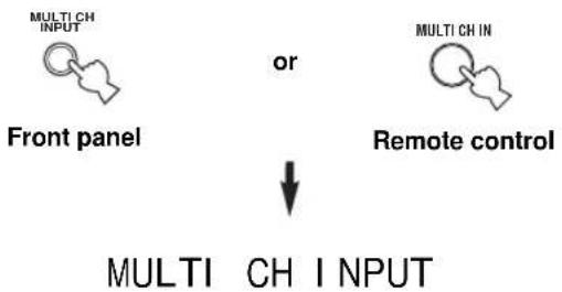
flowchart
graph TD
    A["Front panel"] --> B["or"]
    C["Remote control"] --> D["MULTI CH INPUT"]
    style A fill:#f9f,stroke:#333
    style C fill:#f9f,stroke:#333
    style D fill:#ccf,stroke:#333
Note
When "MULTI CH INPUT" is shown in the front panel display, no other source can be played. To select another input source with INPUT (or one of the input selector buttons), press MULTI CH INPUT (or MULTI CH IN on the remote control) to turn off "MULTI CH INPUT" in the front panel display.
■ Playing video sources in the background
You can combine a video image from a video source with sound from an audio source. For example, you can enjoy listening to classical music while viewing beautiful scenery from the video source on the video monitor.
Use the input selector buttons on the remote control to select a video source, then select an audio source.
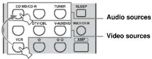
Note
If you want to enjoy audio from the MULTI CH INPUT jacks together with a video source, first select the video source, then press MULTI CH INPUT(or MULTI CH IN on the remote control).
Selecting sound field programs
■ Front panel operation
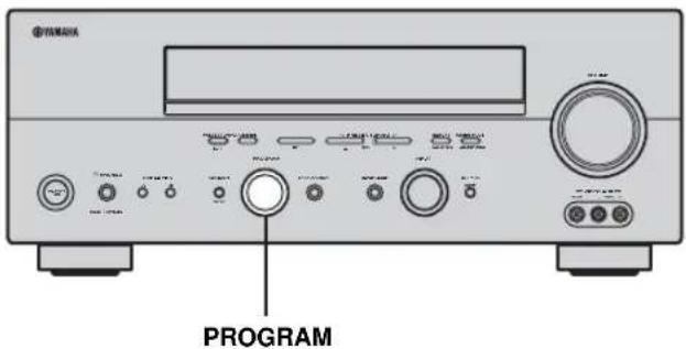
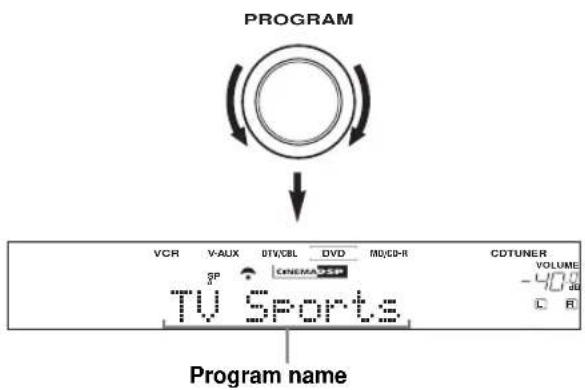
Rotate PROGRAM to select the desired program.
The name of the selected program appears in the front panel display.
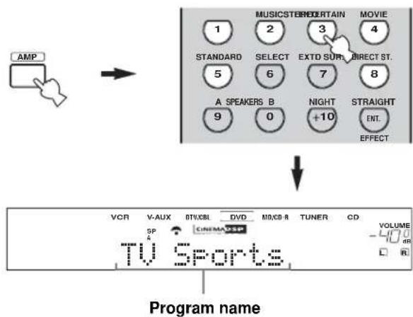
■ Remote control operation
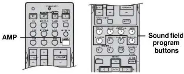
Press AMP to select the AMP mode, then press one of the sound field program buttons to select the desired program.
The name of the selected program appears in the front panel display.
y
Feel free to choose a sound field program based on your listening preference, and not purely on the name of the program itself.
Notes
- When you select an input source, this unit automatically selects the last sound field program used with that source.
- Sound field programs cannot be selected when MULTI CH INPUT is selected.
- Sampling frequencies higher than 48 kHz (except for DTS 96/24 signals) will be sampled down to 48 kHz, then sound field programs will be applied.
■ Enjoying multi-channel software
If you connected a surround back speaker, use this feature to enjoy 6.1-channel playback for multi-channel sources using the Dolby Pro Logic IIx, Dolby Digital EX or DTS-ES decoders.
Press AMP on the remote control to select the AMP mode, then press EXTD SUR. to switch between 5.1 and 6.1-channel playback.
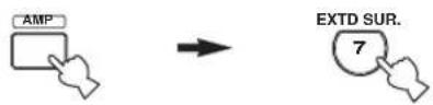
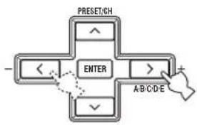
To select a decoder, press j / i repeatedly while PLIIxMusic (etc.) is displayed.
flowchart
graph TD
    A["PRESET/CH"] --> B["ENTER"]
    B --> C["A/B/C/D/E"]
    C --> D["+"]
    style A fill:#f9f,stroke:#333
    style B fill:#ccf,stroke:#333
    style C fill:#cfc,stroke:#333
Auto (AUTO)
When a signal (flag) that can be recognized by the unit is input, the unit selects the optimum decoder for playing back the signal in 6.1 channels.
If the unit cannot recognize the flag or no flag is present in the input signal, it cannot automatically be played in 6.1 channels.
Decoders (select with j / i)
You can select from the following decoders depending on the format of the software you are playing.
PLI1xMusic
For playing back Dolby Digital or DTS signals in 6.1 channels using the Pro Logic IIx music decoder.
EX/ES
For playing back Dolby Digital signals in 6.1 channels using the Dolby Digital EX decoder.
DTS signals are played back in 6.1 channels using the DTS-ES decoder.
EX
For playing back Dolby Digital or DTS signals in 6.1 channels using the Dolby Digital EX decoder.
Off (OFF)
Decoders are not used to create 6.1 channels.
Notes
- Some 6.1-channel compatible discs do not have a signal (flag) which this unit can automatically detect. When playing these kinds of discs with 6.1-channel, select a decoder manually (PLIIx Music, EX/ES or EX).
- 6.1-channel playback is not possible even if EXTD SUR. is pressed in the following cases:
- When “SUR. LR” (see page 50) or “SUR. B” (see page 50) is set to NONE.
- When the source connected to the MULTI CH INPUT jack is being played.
- When the source being played does not contain surround left and right channel signals.
- When a Dolby Digital KARAOKE source is being played.
- When “2ch Stereo” or “Direct Stereo” is selected.
- When the power of this unit is turned off, this setting will be reset to AUTO.
- The Pro Logic IIx decoder is not available when "SUR. B" is set to NONE (see page 50).
■ Enjoying 2-channel software in surround
Signals input from 2-channel sources can also be played back on multiple channels.
Press AMP to select the AMP mode, then press STANDARD on the remote control to switch between the SUR. STANDARD and SUR. ENHANCED programs.

Or press MOVIE to select the MOVIE THEATER program.

Press SELECT on the remote control to select the decoder.

You can select from the following modes depending on the type of software you are playing and your personal preference.
When you select the SUR. STANDARD program:
PRO LOGIC
Dolby Pro Logic processing for any sources.
PLII Movie
Dolby Pro Logic II processing for movie software.
PLII Music
Dolby Pro Logic II processing for music software.
PLI I Game
Dolby Pro Logic II processing for game software.
PLI I x Movie
Dolby Pro Logic IIx processing for movie software.
PLIIX Music
Dolby Pro Logic IIx processing for music software.
PLII x Game
Dolby Pro Logic IIx processing for game software.
Neo: 6 Cinema
DTS processing for movie software.
Neo: 6 Music
DTS processing for music software.
When you select the SUR. ENHANCED or MOVIE THEATER program:
PRO LOGIC
Dolby Pro Logic processing for any sources.
PLII Movie
Dolby Pro Logic II processing for movie software.
PLI I x Movie
Dolby Pro Logic IIx processing for movie software.
Neo: 6 Cinema
DTS processing for movie software.
y
You can also select a decoder by pressing j / i on the remote control when the decoder type is displayed in the front panel display.
Note
The Pro Logic IIx decoder is not available when “SUR. B” is set to NONE (see page 50).
PLAYBACK
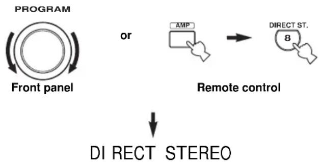
■ Listening to high fidelity stereo sound (Direct Stereo)
Direct Stereo allows you to bypass this unit's decoders and DSP processors to enjoy pure high fidelity sound from 2-channel PCM and analog sources.
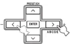
Rotate PROGRAM (or press AMP to select the AMP mode, then press DIRECT ST. on the remote control) to select "DIRECT STEREO".
flowchart
graph TD
    A["PROGRAM"] --> B["Front panel"]
    B --> C["or"]
    C --> D["Remote control"]
    D --> E["DI RECT STEREO"]
    F["AMP"] --> D
    G["DIRECT ST."] --> E
Notes
- To avoid unexpected noise, do not play DTS-encoded CDs in this mode.
- When multi-channel signals (Dolby Digital and DTS) are input, this unit automatically switches to the corresponding analog input. (When DTS is selected as an input mode, no sound will be heard.)
- No sound will be output from the subwoofer.
- TONE CONTROL (page 26) and SET MENU (page 48) settings are not effective.
- The front panel display automatically dims.
- If you press AMP on the remote control to select the AMP mode, then press DIRECT ST., the unit automatically enters Direct Stereo mode and you cannot toggle between the unit's other sound field programs.
■ Night listening modes
The night listening modes are designed to improve listenability at lower volumes or at night. Choose either NIGHT:CINEMA or NIGHT:MUSIC depending on the type of material you are playing.
Press AMP to select the AMP mode, then press NIGHT repeatedly on the remote control to select cinema or music.
When night listening is selected, the NIGHT indicator in the front panel display lights up.

- Select NIGHT:CINEMA when watching films to reduce the dynamic range of film soundtracks and make dialog easier to hear at lower volumes.
- Select NIGHT: MUSIC when listening to music sources to preserve ease-of-listening for all sounds.
- Select OFF if you do not want to use this function.
Press j / i to adjust the effect level while NIGHT:CINEMA or NIGHT:MUSIC is displayed.
This adjusts the level of compression.
flowchart
graph TD
    A["PRESET/CH"] --> B["ENTER"]
    B --> C["A/B/C/D/E"]
    C --> D["+"]
    B --> E["✓"]
    B --> F["<"]
    B --> G["<"]
    B --> H["^"]
Remote control
Effect. Lvl: Ml D
- Select MIN for minimum compression.
- Select MID for standard compression.
- Select MAX for maximum compression.
y
NIGHT:CINEMA and NIGHT:MUSIC adjustments are stored independently.
Notes
- You cannot use the night listening modes with the Direct Stereo program or MULTI CH INPUT.
- The night listening modes may vary in effectiveness depending on the input source and surround sound settings you use.
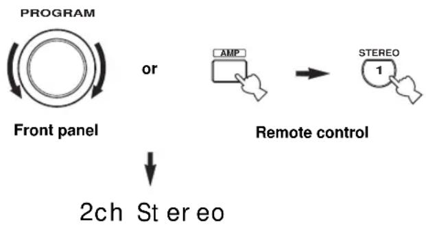
■ Downmixing to 2 channels
You can enjoy 2-channel stereo playback even from multi-channel sources.
Rotate PROGRAM (or press AMP to select the AMP mode, then press STEREO on the remote control) to select 2ch Stereo.
flowchart
graph TD
    A["PROGRAM"] --> B["Front panel"]
    B --> C["2ch Ste er eo"]
    D["AMP"] --> E["Remote control"]
    F["STEREO"] --> E
    E --> G["Output"]
y
You can use a subwoofer with this program when SWFR or BOTH is selected in "BASS OUT".
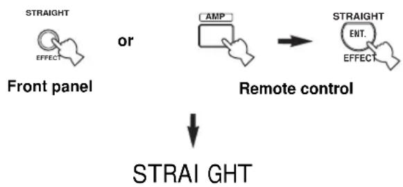
■ Listening to unprocessed input signals
In STRAIGHT mode, two channel stereo sources are output from only the front left and right speakers. Multi-channel sources are decoded straight into the appropriate channels without any additional effect processing.
Press STRAIGHT (or press AMP to select the AMP mode, then press STRAIGHT on the remote control) to select STRAIGHT.
flowchart
graph TD
    A["STRAIGHT"] --> B["OFFECT"]
    C["AMP"] --> D["Remote control"]
    E["STRAIGHT"] --> F["ENT. EFFECT"]
    G["STRAIGHT"] --> H["STRAL GHT"]
    style A fill:#f9f,stroke:#333
    style C fill:#ccf,stroke:#333
    style E fill:#cfc,stroke:#333
    style G fill:#fcc,stroke:#333
Press STRAIGHT (EFFECT) again so that “STRAIGHT” disappears from the display when you want to turn the sound effect back on.
■ Virtual CINEMA DSP
Virtual CINEMA DSP allows you to enjoy the CINEMA DSP programs without surround speakers. It creates virtual speakers to reproduce the natural sound field. If you set “SUR. LR” to NONE (see page 50), Virtual CINEMA DSP activates automatically whenever you select a CINEMA DSP sound field program.
Note
Virtual CINEMA DSP will not activate, even when “SUR. LR” is set to NONE (see page 50) in the following cases:
- When MULTI CH INPUT is selected as the input source.
- When headphones are connected to the PHONES jack.
Selecting input modes
This unit comes with a variety of input jacks. Do the following to select the type of input signals you want to use.
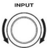
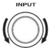
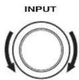
1 Rotate INPUT to select the input source.
2 Press INPUT MODE to select an input mode. In most cases, use AUTO.
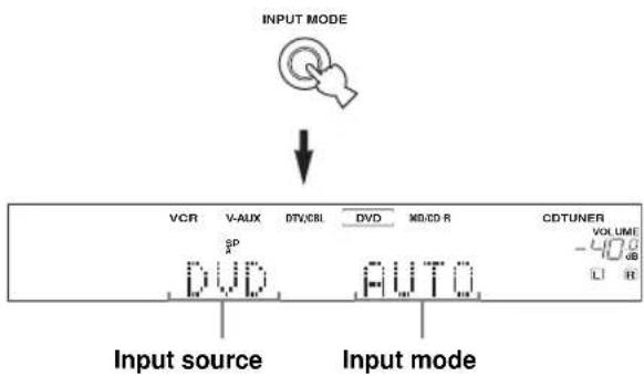
AUTO Automatically selects input signals in the following order:
1) Digital signals*
2) Analog signals
DTS Selects only digital signals encoded in DTS. If no DTS signals are input, no sound is output.
ANALOG Selects only analog signals. If no analog signals are input, no sound is output.
* If this unit detects a Dolby Digital or DTS signal, the decoder automatically switches to the appropriate decoder.
y
You can adjust the default input mode of this unit (see page 52).
Notes
- When playing a DTS-CD/LD, be sure to set INPUT MODE to DTS.
- If the digital output data of the player has been processed in any way, you may not be able to perform DTS decoding even if you make a digital connection between this unit and the player depending on the player.
■ Displaying information about the input source
You can display the type, format and sampling frequency of the current input signal.
1 Select the input source.
2 Press AMP to select the AMP mode, then press STRAIGHT so that "STRAIGHT" appears in the display.
flowchart
graph TD
    A["AMP"] --> B["then"]
    C["STRAIGHT"] --> D["STRAI GHT"]
    E["ENT. EFFECT"] --> D
3 Press u /d to display the following information about the input signal.
flowchart
graph TD
    A["ENTER"] --> B["PRESET/CH"]
    A --> C["A/B/C/DE"]
    A --> D["+"]
    A --> E["✓"]
    A --> F["<<"]
    A --> G["<"]
(Format) Signal format display. When the unit cannot detect a digital signal it automatically switches to analog input.
in Number of source channels in the input signal. For example, a multi-channel soundtrack with 3 front channels, 2 surround channels and LFE, is displayed as “3/2/LFE”.
f s Sampling frequency. When the unit is unable to detect the sampling frequency “Unknown” appears.
r at e Bit rate. When the unit is unable to detect the bit rate "Unknown" appears.
flg Flag data encoded with DTS or Dolby Digital signals that cue this unit to automatically switch decoders.
FM/AM TUNING
Automatic and manual tuning
There are 2 tuning methods; automatic and manual. Automatic tuning is effective when station signals are strong and there is no interference.
■ Automatic tuning
1 Rotate INPUT to select TUNER as the input source.
2 Press FM/AM to select the reception band.
“FM” or “AM” appears in the front panel display.

3 Press TUNING MODE (AUTO/MAN'L MONO) so that the AUTO indicator lights up in the front panel display.

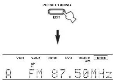
If a colon (:) appears in the front panel display, tuning is not possible. Press PRESET/TUNING (EDIT) to turn the colon (:) off.
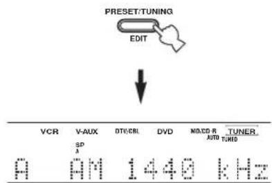
4 Press PRESET/TUNING | /h once to begin automatic tuning.
Press h to tune into a higher frequency, or press l to tune into a lower frequency.
flowchart
graph TD
    A["PRESET/TUNING"] --> B["LEVEL"]
    B --> C["VCR"]
    B --> D["V-AUX"]
    B --> E["DTV/CBL"]
    B --> F["DVD"]
    B --> G["NID/CD-R"]
    B --> H["TUNER"]
    H --> I["Auto THIRED"]
When tuned into a station, the TUNED indicator lights up and the frequency of the received station is shown in the front panel display.
■ Manual tuning
If the signal from the station you want to select is weak, tune into it manually. Manually tuning into an FM station will automatically switch the tuner to monaural reception to increase the signal quality.
1 Select TUNER and the reception band following steps 1 and 2 as described in "Automatic tuning".
2 Press TUNING MODE (AUTO/MAN'L MONO) so that the AUTO indicator disappears from the front panel display.

If a colon (:) appears in the front panel display, tuning is not possible. Press PRESET/TUNING (EDIT) to turn the colon (:) off.

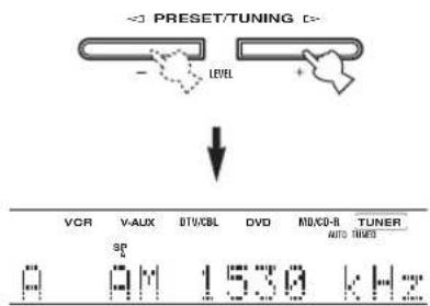
3 Press PRESET/TUNING I /h to tune into the desired station manually.
Hold down the button to continue searching.

Presetting stations
■ Automatically presetting FM stations
You can use the automatic preset tuning feature to store FM stations. This function enables this unit to automatically tune into FM stations with strong signals, and to store up to 40 (8 stations in 5 groups, A1 through E8) of those stations in order. You can then recall any preset station easily by selecting the preset station number.
1 Press FM/AM to select the FM band.

2 Press TUNING MODE (AUTO/MAN'L MONO) so that the AUTO indicator lights up in the front panel display.

If a colon (:) appears in the front panel display, tuning is not possible. Press PRESET/TUNING (EDIT) to turn the colon (:) off.
3 Press and hold MEMORY (MAN'L/AUTO FM) for more than 3 seconds.
The preset number, the MEMORY and AUTO indicators flash. After about 5 seconds, automatic presetting starts from the frequency currently displayed and proceeds toward the higher frequencies.
When automatic preset tuning is completed, the front panel display shows the frequency of the last preset station.
Notes
- Any stored station data existing under a preset number is cleared when you store a new station under that preset number.
- If the number of received stations does not reach 40 (E8), automatic preset tuning has automatically stopped after searching all stations.
- Only FM stations with sufficient signal strength are stored automatically by automatic preset tuning. If the station you want to store is weak in signal strength, tune into it manually and store it by following the procedure in “Manually presetting stations”.
Automatic preset tuning options:
You can select the preset number from which this unit will store FM stations and/or begin tuning toward lower frequencies.
After pressing MEMORY in step 3:
1 Press A/B/C/D/E (NEXT), then PRESET/TUNING I / h to select the preset number under which the first station will be stored. Automatic preset tuning will stop when stations have all been stored up to E8.
2 Press PRESET/TUNING (EDIT) to turn off the colon (:) and then press PRESET/TUNING | to begin tuning toward the lower frequencies.
Memory back-up
The memory back-up circuit prevents the stored data from being lost even if this unit is set in the standby mode, the power cord is disconnected from the AC outlet, or the power supply is temporarily cut due to power failure. However, if the power is cut for more than one week, the preset stations may be cleared. If so, store the stations again by using the presetting station methods.
■ Manually presetting stations
You can also store up to 40 stations (8 stations x 5 groups) manually.
1 Tune into a station.
See page 33 for tuning instructions.
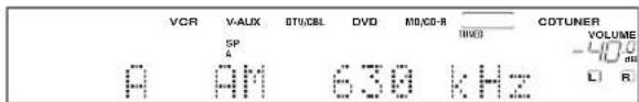
When tuned into a station, the front panel display shows the frequency of the station received.
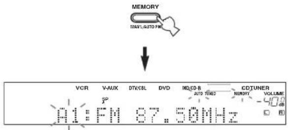
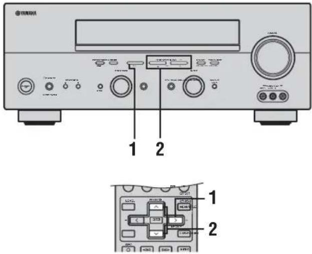
2 Press MEMORY (MAN'L/AUTO FM).
The MEMORY indicator flashes for about 5 seconds.

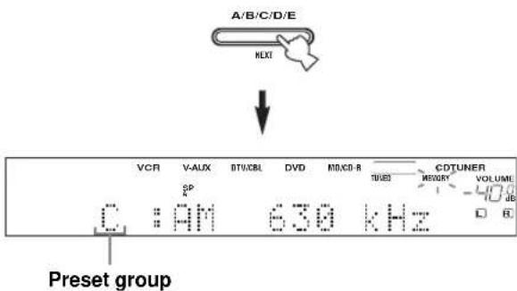
3 Press A/B/C/D/E (NEXT) repeatedly to select a preset station group (A to E) while the MEMORY indicator is flashing.
The group letter appears. Check that the colon (:) appears in the front panel display.
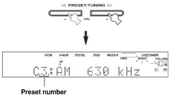
4 Press PRESET/TUNING | /h to select a preset station number (1 to 8) while the MEMORY indicator is flashing.
Press h to select a higher preset station number. Press l to select a lower preset station number.
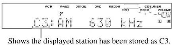
5 Press MEMORY (MAN'L/AUTO FM) on the front panel while the MEMORY indicator is flashing.
The station band and
frequency appear in the front panel display with the preset group and number you have selected.

6 Repeat steps 1 to 5 to store other stations.
Notes
- Any stored station data existing under a preset number is cleared when you store a new station under that preset number.
- The reception mode (stereo or monaural) is stored along with the station frequency.
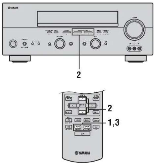
Selecting preset stations
You can tune any desired station simply by selecting the preset station number under which it was stored.
y When performing this operation with the remote control, first press TUNER to set the remote to tuner mode.
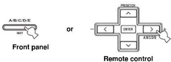
1 Press A/B/C/D/E (NEXT) (or A/B/C/D/E i on the remote control) to select the preset station group.
The preset group letter appears in the front panel display and changes each time you press the button.
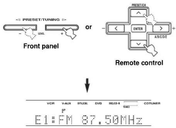
2 Press PRESET/TUNING | /h (or PRESET/CH u /d on the remote control) to select a preset station number (1 to 8).
The preset group and number appear in the front panel display along with the station band, frequency and the TUNED indicator lights up.
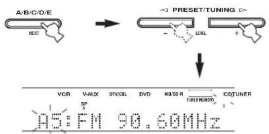
Exchanging preset stations
You can exchange the assignment of two preset stations with each other. The example below describes the procedure for exchanging preset station "E1" with "A5".
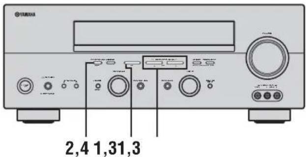
1 Select preset station "E1".
See "Selecting preset stations".
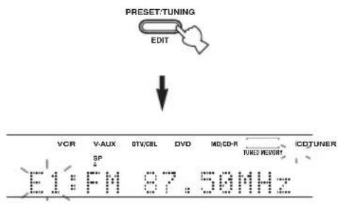
2 Press and hold PRESET/TUNING (EDIT) for more than 3 seconds.
"E1" and the MEMORY indicator flash in the front panel display.
3 Select preset station "A5" using A/B/C/D/E and PRESET/TUNING I /h.
"A5" and the MEMORY indicator flash in the front panel display.
flowchart
graph TD
    A["A/B/C/D/E"] --> B["PRESET/TUNING"]
    B --> C["VCR"]
    B --> D["V-AUX"]
    B --> E["DTV/CBL"]
    B --> F["DVD"]
    B --> G["NG/CO-R"]
    B --> H["CDTUNER"]
    C --> I["SP"]
    D --> J["1"]
    E --> K["3"]
    F --> L["4"]
    G --> M["5"]
    H --> N["6"]
    I --> O["A5: FM 90.60MHz"]
    J --> O
    K --> O
    L --> O
    M --> O
    N --> O
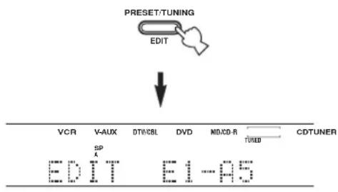
4 Press PRESET/TUNING (EDIT) again.
The stations stored at the two preset assignments are exchanged.
flowchart
graph TD
    A["PRESET/TUNING"] --> B["EDIT"]
    B --> C["VCR"]
    C --> D["V-AUX"]
    D --> E["DTV/CBL"]
    E --> F["DVD"]
    F --> G["NID/CD-R"]
    G --> H["CDTUNER"]
    H --> I["TUREND"]
    I --> J["EDIT"]
    J --> K["E1-AS"]
Receiving Radio Data System stations
Radio Data System is a data transmission system used by FM stations in many countries. The Radio Data System function is carried out among the network stations.
This unit can receive various Radio Data System data such as PS (Program Service name), PTY (Program Type), RT (Radio Text), CT (Clock Time), EON (Enhanced Other Networks) when receiving Radio Data System broadcasting stations.
■ PS (Program Service name) mode
The name of the Radio Data System station being received is displayed.
■ PTY (Program Type) mode
There are 15 program types to classify Radio Data System stations.
| NEWS News | |
| AFFAIRS Current affairs | |
| INFO General information | |
| SPORT Sports | |
| EDUCATE Education | |
| DRAMA Drama | |
| CULTURE Culture | |
| SCIENCE Science | |
| VARIED Light entertainment | |
| POP M Pops | |
| ROCK M | Rock |
| M.O.R. M | Middle-of-the-road music (easy-listening) |
| LIGHT M | Light classics |
| CLASSICS | Serious classics |
| OTHER M | Other music |
■ RT (Radio Text) mode
Information about the program (such as the title of the song or name of the singer) on the Radio Data System station being received is displayed using a maximum of 64 alphanumeric characters, including the umlaut symbol. If other characters are used for RT data, they are displayed with an underbar (_).
■ CT (Clock Time) mode
The current time is displayed and updated every minute. If the data are accidentally cut off, “CT WAIT” may appear.
■ EON (Enhanced Other Networks)
See "EON function" on page 41.
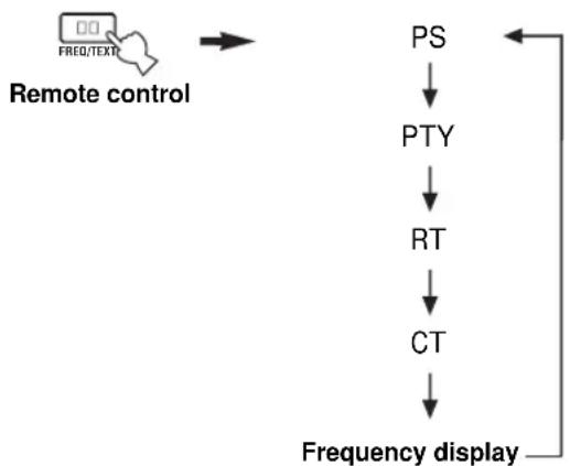
Changing the Radio Data System mode
Four modes are available for displaying Radio Data System data. The PS, PTY, RT and/or CT indicators that correspond to the Radio Data System data services offered by the station light up in the front panel display.
1 Press TUNER on the remote control to set this unit to tuner mode.

2 Press FREQ/TEXT repeatedly on the remote control to display the various Radio Data System data offered by the transmitting station.
flowchart
graph TD
    A["Remote control"] --> B["PS"]
    B --> C["PTY"]
    C --> D["RT"]
    D --> E["CT"]
    E --> F["Frequency display"]
Notes
- Do not press FREQ/TEXT until a Radio Data System indicator lights up in the front panel display. You cannot change the mode if you press the button prior to this. This is because this unit has not finished receiving all of the Radio Data System data from the station.
- Radio Data System data not offered by the station cannot be selected.
- This unit cannot utilize the Radio Data System data source if the signal received is not strong enough. In particular, the RT mode requires a large amount of data, so it is possible that the RT mode may not be displayed even if other Radio Data System modes (PS, PTY, etc.) are displayed.
- Radio Data System data may not be received under poor reception conditions. In such cases, press TUNING MODE (AUTO/MAN'L MONO) so that the AUTO indicator disappears from the front panel display. Although this will change the reception mode to manual, Radio Data System data may be displayed when you change the display to Radio Data System mode.
- If the signal strength is weakened by external interference during the reception of a Radio Data System station, the Radio Data System data service may be cut off suddenly and “...WAIT” will appear in the front panel display.
PTY SEEK function
If you select the desired program type, this unit automatically searches all preset Radio Data System stations that are broadcasting a program of the required type.
y When performing this operation with the remote control, first press TUNER to set the remote to tuner mode.
1 Press PTY SEEK MODE on the remote control to set this unit in the PTY SEEK mode.
The program type of the station being received or "NEWS" flashes in the front panel display. To exit from the PTY SEEK mode, press PTY SEEK MODE again.

flowchart
graph LR
    A["MODE -P"] --> B[" Ek-START "]
    C["Remote control"] --> D["→"]
    E["NEWS"] --> F["Flashes"]
2 Press PRESET/TUNING I /h (or PRESET/CH u /d on the remote control) to select the desired program type.
The selected program type appears in the front panel display.
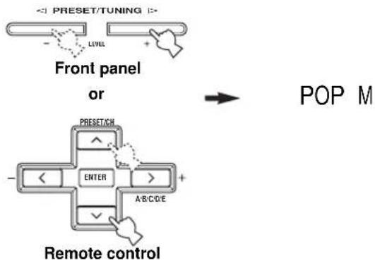
flowchart
graph TD
    A["Front panel or"] --> B["Remote control"]
    B --> C["POP M"]
    style A fill:#f9f,stroke:#333
    style B fill:#ccf,stroke:#333
    style C fill:#dfd,stroke:#333
3 Press PTY SEEK START on the remote control to begin searching all preset Radio Data System stations.
The selected program type flashes and the PTY HOLD indicator lights up in the front panel display while searching for stations. To cancel searching, press PTY SEEK START again.

flowchart
graph LR
    A["MODE -PTY SEEK -START"] --> B["Remote control"]
    C["PTY HOLD"] --> D["Lights up"]
- The unit stops searching when it finds a station broadcasting the selected type of program.
- If the found station is not the one you desire, press PTY SEEK START again. This unit resumes searching for another station broadcasting the same type of program.
EON function
This function uses the EON data service on the Radio Data System station network. If you select the desired program type (NEWS, INFO, AFFAIRS or SPORT), this unit automatically searches for all preset Radio Data System stations that are scheduled to broadcast the selected type of program and switches from the station currently being received to the new station when the broadcast starts.
y
When performing this operation with the remote control, first press TUNER to set the remote to tuner mode.
Note
This function can only be used when a Radio Data System station that offers the EON data service is being received. When such a station is being received, the EON indicator lights up in the front panel display.
1 Check that the EON indicator is lit in the front panel display.
If the EON indicator is not lit up, tune into another Radio Data System station so that the EON indicator lights up.
2 Press EON repeatedly on the remote control to select the desired program type (NEWS, INFO, AFFAIRS or SPORT).
The selected program type name appears in the front panel display.


NEWS
Remote control
- If a preset Radio Data System station type starts broadcasting the selected type of program, the unit automatically switches from the program being received to that program. (The EON indicator flashes.)
- When broadcasting of the selected program ends, the unit returns to the previous station (or another program on the same station).
■ To cancel this function
Press EON repeatedly until no program type name is shown in the front panel display.
RECORDING
Recording adjustments and other operations are performed from the recording components. Refer to the operating instructions for those components.
1 Turn on the power of this unit and all connected components.
2 Select the source component you want to record from.
Front panel
or
Remote control
3 Start playback (or select a broadcast station) on the source component.
4 Start recording on the recording component.
y
Do a test recording before you start an actual recording.
Notes
- When this unit is set in the standby mode, you cannot record between other components connected to this unit.
- The setting of TONE CONTROL, VOLUME, "SP LEVEL" (page 51) and the sound field programs does not affect recorded material.
- A source connected to the MULTI CH INPUT jacks of this unit cannot be recorded.
- S-video and composite video signals pass independently through this unit's video circuits. Therefore, when recording or dubbing video signals, if your video source component is connected to provide only an S-video (or only a composite video) signal, you can record only an S-video (or only a composite video) signal to your VCR.
- Digital signals input to the DIGITAL INPUT jacks are not output to the analog AUDIO OUT (L/R) jacks for recording. Likewise, analog signals input to the AUDIO IN (L/R) jacks are not output to the DIGITAL OUTPUT jack. Therefore, if your source component is connected to provide only digital (or analog) signals, you can only record digital (or analog) signals.
- A given input source is not output on the same REC OUT channel. (For example, the signal input from VCR IN is not output on VCR OUT.)
- Check the copyright laws in your country to record from records, CDs, radio, etc. Recording of copyrighted material may infringe copyright laws.
If you playback a video source that uses scrambled or encoded signals to prevent it from being dubbed, the picture itself may be disturbed due to those signals.
■ Special considerations when recording DTS software
The DTS signal is a digital bitstream. Attempting to digitally record the DTS bitstream will result in noise being recorded. Therefore, if you want to use this unit to record sources that have DTS signals recorded on them, the following considerations and adjustments need to be made.
For DVDs and CDs encoded with DTS, when your player is compatible with the DTS format, follow its operating instructions to make a setting so that the analog signal will be output from the player.
SOUND FIELD PROGRAM DESCRIPTIONS
This unit is equipped with a variety of precise digital decoders that allow you to enjoy multi-channel playback from almost any sound source (stereo or multi-channel). This unit is also equipped with a YAMAHA digital sound field processing (DSP) chip containing several sound field programs which you can use to enhance your playback experience. Most of these sound field programs are precise digital recreations of actual acoustic environments found in famous concert halls, music venues, and movie theaters.
y
The YAMAHA CINEMA DSP modes are compatible with all Dolby Digital, DTS, and Dolby Surround sources. Set the input mode to AUTO (see page 32) to enable this unit to automatically switch to the appropriate digital decoder according to the input signal.
Notes
- This unit's DSP sound field programs are recreations of real-world acoustic environments made from precise measurements taken in the actual hall, etc. Thus you may notice variations in the strength of the reflections coming from the front, back, left and right.
- Feel free to choose a sound field program based on your listening preference, and not purely on the name of the program itself.
For movie/video sources
You can select from the following sound fields when playing movie or video sources. The sound fields marked “MULTI” can be used with multi-channel sources, like DVD, digital TV, etc. Those marked “2-CH” can be used with 2-channel (stereo) sources like TV programs, video tapes, etc.
Program selection methods vary depending on sound field program types. For details on how to select sound field programs, see “Selecting sound field programs” on pages 27 to 31.
| Remote control button | Program Features | Sources | |
| 1 | STEREO:2ch Stereo | Downmixes multi-channel sources to 2 channels (left and right) or plays back 2-channel sources as is. | MULTI2-CH |
| 2 | MUSIC:Pop/ Rock | This program lends an enthusiastic atmosphere to the sound, giving you the feeling you are at an actual jazz or rock concert. | |
| 3 | ENTERTAINMENT:TV Sports | Though the presence sound field is relatively narrow, the surround sound field employs the sound environment of a large concert hall. This effect enhances the experience of watching various TV programs such as news, variety shows, music programs or sports programs. | |
| ENTERTAINMENT:Mono Movie | This program is provided for reproducing monaural video sources (such as old movies). The program produces the optimum reverberation to create sound depth using only the presence sound field. | ||
| ENTERTAINMENT:Game | This program adds a deep and spatial feeling to video game sounds. |
SOUND FIELD PROGRAM DESCRIPTIONS
| Remote control button | Program Features | Sources | |
| 4 | MOVI E THEATER: Spect acl e | CINEMA DSP processing. This program creates the extremely wide sound field of a 70-mm movie theater. It precisely reproduces the source sound in detail, making both the video and the sound field incredibly real. This is ideal for any kind of video source encoded with Dolby Surround, Dolby Digital or DTS (especially large-scale movie productions). | MULTI 2-CH |
| MOVI E THEATER: Sci - Fi | CINEMA DSP processing. This program clearly reproduces dialog and sound effects in the latest sound form for science fiction films, thus creating a broad and expansive cinematic space amid silence. You can enjoy science fiction films in a virtual-space sound field that includes Dolby Surround, Dolby Digital and DTS-encoded software employing the most advanced techniques. | ||
| MOVI E THEATER: Advent ur e | CINEMA DSP processing. This program is ideal for precisely reproducing the sound design of the newest 70-mm and multi-channel soundtrack films. The sound field is made to be similar to that of the newest movie theaters, so the reverberations of the sound field itself are restrained as much as possible. | ||
| MOVI E THEATER: Gener al | CINEMA DSP processing. This program is for reproducing sounds from 70-mm and multi-channel soundtrack films, and is characterized by soft and extensive sound field. | ||
| 5 | SUR. STANDARD | Standard processing for the selected decoder. | |
| SUR. ENHANCED | Enhanced processing for the selected decoder. |
For music sources
You can select from the following sound fields when playing music sources, like CD, FM/AM broadcasting, tapes, etc.
Program selection methods vary depending on sound field program types. For details on how to select sound field programs, see “Selecting sound field programs” on pages 27 to 31.
| Remote control button | Program Features | Sources | |
| 1 | STEREO:2ch Stereo | 2-channel (left and right) playback. | 2-CH |
| STEREO:6ch Stereo | Use to increase the output stereo sources (in stereo) from all speakers. This provides a larger sound field and is ideal for background music at parties, etc. | ||
| 2 | MUSI C:Hall i n Vienna | HiFi DSP processing. A classic shoe-box type concert hall with approximately 1700 seats. Pillars and ornate carvings create extremely complex reflections which produce a very full, rich sound. | MULTI 2-CH |
| MUSI C:The Bt t m Line | HiFi DSP processing. This is the sound field at stage front in “The Bottom Line”, a famous New York jazz club. The floor can seat 300 people to the left and right in a sound field offering a real and vibrant sound. | ||
| MUSI C:The Roxy Tht r | HiFi DSP processing. The ideal program for lively, dynamic rock music. The data for this program was recorded at LA’s “hottest” rock club. The listener’s virtual seat is at the center-left of the hall. | ||
| 3 | ENTERTAI NMENT:Di sco | HiFi DSP processing. This program recreates the acoustic environment of a lively disco in the heart of a big city. The sound is dense and highly concentrated. It is also characterized by high-energy, “immediate” sound. | |
| 5 | SUR. STANDARD | Standard processing for the selected decoder. | |
| SUR. ENHANCED | Enhanced processing for the selected decoder. |
ADVANCED OPERATIONS
Using the sleep timer
Use this feature to automatically set this unit in the standby mode after a certain amount of time. The sleep timer is useful when you are going to sleep while this unit is playing or recording a source. The sleep timer also automatically turns off any external components connected to AC OUTLET(S).
■ Setting the sleep timer
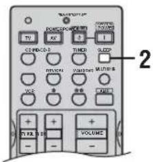
1 Select a source and start playback on the source component.
2 Press SLEEP repeatedly to set the amount of time.
Each time you press SLEEP, the front panel display changes as shown below. The SLEEP indicator flashes while switching the amount of time for the sleep timer.

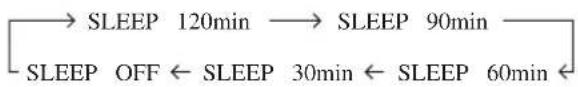
The SLEEP indicator lights up in the front panel display, and the display returns to the selected sound field program.
SLEEP indicator
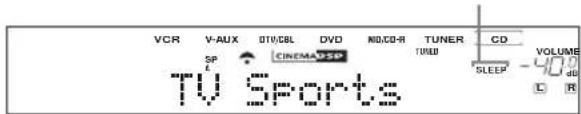
■ Canceling the sleep timer
Press SLEEP repeatedly until "SLEEP OFF" appears in the front panel display.
After a few seconds, "SLEEP OFF" disappears, and the SLEEP indicator goes off.

y
The sleep timer setting can also be canceled by pressing STANDBY on the remote control (or STANDBY/ON on the front panel) to set this unit to the standby mode.
Manually adjusting speaker levels
You can adjust the output level of each speaker while listening to a music source. This is also possible when playing sources through the MULTI CH INPUT jacks. Please note that this operation will override the level adjustments made in “BASIC SETUP” (page 22) and “SP LEVEL” (page 51).
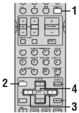
1 Press AMP.
2 Press LEVEL repeatedly to select the speaker you want to adjust.
FRONT L Front left speaker level
CENTER Center speaker level
FRONT R Front right speaker level
SUR. R Surround right speaker level
SUR. B Surround back speaker level
SUR. L Surround left speaker level
SWFR Subwoofer level
y
Once you press LEVEL, you can also select the speaker by pressing u /d.
3 Press j / i to adjust the speaker output level.
The control range is from +10 dB to -10 dB.
4 Press ENTER when you have completed your adjustment.
y
This operation can also be performed using the controls on the front panel. Press NEXT repeatedly to select the speaker you want to adjust, then press LEVEL -/+ to adjust the output level.
SET MENU
You can use the following parameters in SET MENU to adjust a variety of system settings and customize the way this unit operates. Change the initial settings (indicated in bold under each parameter) to reflect the needs of your listening environment.
■ BASIC SETUP
Use to quickly setup basic system parameters (see page 22).
■ MANUAL SETUP
Use to adjust speaker and system settings manually.
1 SOUND MENU
Use to manually adjust any speaker setting, alter the quality and tone of the sound output by the system or compensate for video signal processing delays when using LCD monitors or projectors.
y
Most of the parameters described in SOUND MENU are set automatically when you perform “BASIC SETUP” (see page 22). You can use SOUND MENU to make further adjustments.
| Item Features Page | ||
| A) SPEAKER SET | Selects the size of each speaker, the speakers for low-frequency signal output, and the cross over frequency. | 50 |
| B) SPEAKER LEVEL | Adjusts the output level of each speaker. | 51 |
| C) SP DI STANCE | Adjusts the delay time of each speaker. | 51 |
| D) CENTER GEQ | Adjusts the tonal quality of the center speaker. | 51 |
| E) LFE LEVEL | Adjusts the output level of the LFE channel for Dolby Digital or DTS signals. | 51 |
| F) D. RANGE | Adjusts the dynamic range for Dolby Digital or DTS signals. | 51 |
| G) AUDIO SET | Customizes the muting level, audio delay and tone bypass settings. | 52 |
2 INPUT MENU
Use to reassign digital input/outputs and select the input mode.
| Item Features Page | ||
| A) I / O ASSI GN | Assigns jacks according to the component to be used. | 52 |
| B) I NPUT MODE | Selects the initial input mode of the source. | 52 |
| C) I NPUT RENAME | Changes the name of the inputs. | 53 |
3 OPTION MENU
Use to adjust the optional system parameters.
| Item Features Page | ||
| A) DI SPLAY SET | Adjusts the brightness of the display and converts video signals. | 53 |
| B) MEMORY GUARD | Locks sound field program parameters and other SET MENU settings. | 53 |
| C) PARAM. I NI | Initializes the parameters of a group of sound field programs. | 54 |
| D) MULTI ZONE | Specifies the location of the speakers connected to the SPEAKERS B terminals. | 54 |
Using SET MENU
Use the remote control to access and adjust each parameter.
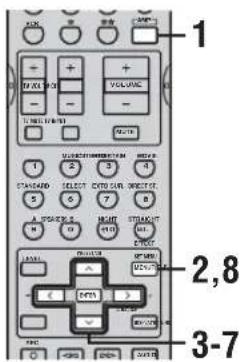
y You can change SET MENU parameters while the unit is reproducing sound.
Note
You cannot change some SET MENU parameters while the unit is in either cinema or music night listening mode.
1 Press AMP.
2 Press SET MENU.
"BASIC SETUP" appears in the front panel display.
3 Press u / d to display MANUAL SETUP.
MANUAL SETUP
4 Press ENTER to enter MANUAL SETUP.
1 SOUND MENU appears in the front panel display.
1 SOUND MENU
5 Press u /d to display the desired menu.
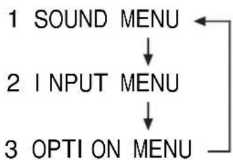
flowchart
graph TD
    A["1 SOUND MENU"] --> B["2 INPUT MENU"]
    B --> C["3 OPTI ON MENU"]
6 Press ENTER to enter the displayed menu.
Repeat steps 5 and 6 to navigate to and enter the items you want to adjust.
To return to the previous menu level, press RETURN.
7 Press u /d and ENTER to select the submenu, then press u /d to select the item and j /i to change the parameter.
Repeat this operation to select and adjust each setting. To return to the previous menu level, press RETURN.
8 To exit, press SET MENU when finished.
Memory back-up
The memory back-up circuit prevents the stored data from being lost even if this unit is in the standby mode. However, if the power cord is disconnected from the AC outlet, or the power supply is cut for more than one week, the stored data will be lost. If so, adjust the items again.
1 SOUND MENU
Use to manually adjust any speaker setting or compensate for video signal processing delays when using LCD monitors or projectors. Most of the SOUND MENU parameters are set automatically when you perform “BASIC SETUP” (see page 22).
■ Speaker settings A) SPEAKER SET
Use to manually adjust any speaker setting.
y
If you are not satisfied with the bass sounds from your speakers, you can change these settings according to your preference.
Front speakers FRONT
Choices: LARGE, SMALL
- Select LARGE if you have large front speakers. The unit directs the entire range of the front left and right channel signals to the front left and right speakers.
- Select SMALL if you have small front speakers. The unit directs the low-frequency signals of the front channel to the speakers selected with “BASS OUT”.
Center speaker CENTER
Choices: LRG, SML, NONE
- Select LRG if you have a large center speaker. The unit directs the entire range of the center channel signal to the center speaker.
- Select SML if you have a small center speaker. The unit directs the low-frequency signals of the center channel to the speakers selected with “BASS OUT”.
- Select NONE if you do not have a center speaker. The unit directs all of the center channel signal to the front left and right speakers.
Surround left/right speakers SUR. LR
Choices: LRG, SML, NONE
- Select LRG if you have large surround left and right speakers. The entire range of the surround channel signal is directed to the surround left and right speakers.
- Select SML if you have small surround left and right speakers. The low-frequency signals of the surround channel are directed to the speakers selected with "BASS OUT".
- Select NONE if you do not have surround speakers. This will set the unit to the Virtual CINEMA DSP mode (see page 31) and automatically set the surround back speaker setting (SUR. B) to NONE.
Surround back speaker SUR. B
Choices: LRG, SML, NONE
- Select LRG if you have a large surround back speaker.
- Select SML if you have a small surround back speaker. The low-frequency signals of the surround back channel are directed to the speakers selected with “BASS OUT”, and the rest of the frequency signals are directed to the surround back speaker.
- Select NONE if you do not have a surround back speaker. The unit directs all of the surround back channel signal to the surround left and right speakers.
Bass out BASS OUT
Low-frequency (bass) signals can be directed to the subwoofer and/or the front left and right speakers according to the characteristics of your system. This setting also determines the routing of the LFE (low-frequency effect) signals found in Dolby Digital or DTS sources.
Choices: SWFR (subwoofer), FRONT, BOTH
- Select SWFR if you connect a subwoofer. LFE and low-frequency signals from other channels are directed to the subwoofer according to the speaker settings.
- Select FRONT if you do not use a subwoofer. LFE and low-frequency signals from other channels are directed to the front speakers according to the speaker settings (even if you have previously set the front speakers to SML).
- Select BOTH if you connect a subwoofer and you want to output low-frequency signals from front channels to both the front speakers and subwoofer. LFE and low-frequency signals from other channels are also directed to the subwoofer according to the speaker settings. Use this function to reinforce low-frequency signals using the subwoofer when playing back sources such as CDs.
Cross over CrossOver
Use this feature to select a cross-over (cut-off) frequency for all low-frequency signals. All frequencies below the selected frequency will be sent to the subwoofer.
Choices: 40Hz, 60Hz, 80Hz, 90Hz, 100Hz, 110Hz, 120Hz, 160Hz, 200Hz
Subwoofer phase SWFR PHASE
If bass sounds are lacking or unclear, use this feature to switch the phase of your subwoofer.
Choices: NRM (normal), REV (reverse)
- Select NRM if you do not want to reverse the phase of your subwoofer.
- Select REV to reverse the phase of your subwoofer.
■ Speaker level B) SP LEVEL
Use these settings to manually balance the level of each speaker selected in SPEAKER SET (page 50).
Choices: -10.0 dB to +10.0 dB
- FL adjusts the balance of the front left speaker.
• FR adjusts the balance of the front right speaker. - C adjusts the balance of the center speaker.
- SL adjusts the balance of the surround left speaker.
- SR adjusts the balance of the surround right speaker.
- SB adjusts the balance of the surround back speaker.
- SWFR adjusts the balance of the subwoofer.
y
To calibrate, use the test tone feature (see page 24).
■ Speaker distance C) SP DI STANCE
Use this feature to manually input the distance of each speaker and adjust the delay applied to respective channel. Ideally, each speaker should be the same distance from the main listening position. However, this is not possible in most home situations. Thus, a certain amount of delay must be applied to the sound from each speaker so that all sound will arrive at the listening position at the same time.
Unit UNI T
Choices: meters (m), feet (ft)
- Select meters to input speaker distances in meters.
- Select feet to input speaker distances in feet.
Speaker distances
Choices: 0.3 to 24.0 m
- FRONT L adjusts the distance of the front left speaker. Initial setting: 3.0 m
- FRONT R adjusts the distance of the front right speaker. Initial setting: 3.0 m
- CENTER adjusts the distance of the center speaker. Initial setting: 3.0 m
- SUR. L adjusts the distance of the surround left speaker. Initial setting: 3.0 m
- SUR. R adjusts the distance of the surround right speaker. Initial setting: 3.0 m
- SUR. B adjusts the distance of the surround back speaker. Initial setting: 2.10 m
- SWFR adjusts the distance of the subwoofer. Initial setting: 3.0 m
■ Center graphic equalizer D) CENTER GEQ
Use this feature to adjust the built-in 5-band graphic equalizer for the center channel so that the tonal quality of the center speaker matches that of the front speakers. You can make adjustments listening to the currently selected source component or a test tone.
You can adjust 5 frequency bands:
100Hz, 300Hz, 1kHz, 3kHz, 10kHz
Choices: -6 to +6 dB
- Select ON to output test tones from the front left and center speakers, and adjust the tonal quality of the center speaker.
- Select OFF to stop the test tone and output the currently selected source component.
■ Low-frequency effect level E) LFE LEVEL
Use to adjust the output level of the LFE (low-frequency effect) channel according to the capacity of your subwoofer or headphones. The LFE channel carries low-frequency special effects which are only added to certain scenes. This setting is effective only when this unit decodes Dolby Digital or DTS signals.
Choices: -20 to 0 dB
Speaker SP LFE
Select to adjust the speaker LFE level.
Headphone HP LFE
Select to adjust the headphone LFE level.
Note
Depending on the “LFE LEVEL” setting, some signals may not be output from the SUBWOOFER OUTPUT jack.
■ Dynamic range F) D. RANGE
Use to select the amount of dynamic range compression to be applied to your speakers or headphones. This setting is effective only when the unit is decoding Dolby Digital and DTS signals.
Choices: MAX (maximum), STD (standard), MIN (minimum)
Speaker SP D. R
Select to adjust the speaker compression.
Headphone HP D. R
Select to adjust the headphone compression.
- Select MAX for feature films.
- Select STD for general use.
- Select MIN for listening to sources at low volume levels.
■ Audio settings G) AUDI O SET
Use to customize this units overall audio settings.
Muting type MUTE TYP.
Use to adjust how much the mute function reduces the output volume.
Choices: FULL, -20dB
- Select FULL to completely halt all output of sound.
- Select -20dB to reduce the current volume by 20~dB .
Audio delay A. DELAY
Use to delay the sound output and synchronize it with the video image. This may be necessary when using certain LCD monitors or projectors.
Choices: 0 to 160 ms
Tone bypass TC. BYPASS
Use to select whether audio output bypasses tone control circuitry when TREBLE and BASS (page 26) are set to 0 dB.
Choices: AUTO, OFF
- Select AUTO if you want signals to bypass tone control circuitry to provide the purest signal possible.
- Select OFF if you do not want signals to bypass tone control circuitry.
2 INPUT MENU
Use to reassign digital input/outputs and select the input mode.
■ Input/output assignment I/O ASSIGN
You can assign jacks according to the component to be used if this unit's initial settings do not correspond to your needs. Change the following parameters to reassign the respective jacks and effectively connect more components. Once the inputs have been reassigned, you can select the corresponding component by using INPUT on the front panel or the input selector buttons on the remote control.
For COMPONENT VIDEO jacks A (C. V[A]) and B (C. V[B])
Choices: [A] DVD, DTV/CBL, V-AUX, VCR [B] DVD, DTV/CBL, V-AUX, VCR
For OPTICAL OUTPUT jack 1 (OUT(1))
Choices: MD/CD-R, CD, V-AUX, DTV/CBL, VCR, DVD
For OPTICAL INPUT jacks 2 (I N (2)), 3 (I N (3)) and 4 (I N (4))
Choices: (2) CD, MD/CD-R, DVD, DTV/CBL, V-AUX, VCR
(3) CD, MD/CD-R, DVD, DTV/CBL, V-AUX, VCR
(4) CD, MD/CD-R, DVD, DTV/CBL, V-AUX, VCR
For COAXIAL INPUT jack 5 (IN (5))
Choices: CD, MD/CD-R, DVD, DTV/CBL, V-AUX, VCR
Notes
- You cannot select a specific item more than once for the same type of jack.
- When you connect a component to both the COAXIAL and OPTICAL jacks, priority is given to the input signals from the COAXIAL jack.
■ Input mode B) INPUT MODE
Use this feature to designate the input mode for sources connected to the DIGITAL INPUT jacks when you turn on this unit (see page 32 for details about the input mode).
Choices: AUTO, LAST
- Select AUTO to allow this unit to automatically detect the type of input signal and select the appropriate input mode.
- Select LAST to set this unit to automatically select the last input mode used for that source.
Note
Even if LAST is selected, the last setting for the EXTD SUR. button will not be recalled.
■ Input rename C) INPUT RENAME
Use this feature to change the name of the inputs in the front panel display.
1 Press an input selector button to select the input you want to change the name of.
2 Press AMP.
3 Press j / i to place the _ (under-bar) under the space or the character you want to edit.
4 Press u /d to select the character you want, then use j /i to move to the next space.
- You can use up to 8 characters for each input.
- Press d to change the character in the following order, or press u to go in the reverse order: A to Z, a space, 0 to 9, a space, a to z, a space, symbols (#, *, -, +, etc.).
5 Repeat steps 1 through 4 to rename each input.
6 To exit, press SET MENU when finished.
3 OPTION MENU
Use to adjust the optional system parameters.
■ Display settings A) DI SPLAY SET
Dimmer DI MMER
Use to adjust the brightness of the front panel display. Choices: -4 to 0
Video conversion V. CONV.
Use this feature to turn on/off conversion of composite (VIDEO) signals to S-video signals. This allows you to output converted video signals from the S VIDEO jacks when no S-video or component signals are input. This feature also converts S-video signals to component signals when no component signals are input.
Choices: ON, OFF
- Select OFF not to convert any signals (except S-video signals to composite signals).
- Select ON to convert composite signals to S-video and component signals, and to convert S-video signals to component signals.
- Regardless of the setting, S-video signals are always converted to composite signals.
Notes
- Converted video signals are only output to the MONITOR OUT jacks. When recording you must make the same type of video connections (i.e., S-video) between each component.
- When converting composite video or S-video signals from a VCR to component signals, the picture quality may suffer depending on your VCR.
■ Memory guard B) MEMORY GUARD
Use this feature to prevent accidental changes to DSP program parameter values and other system settings.
Choices: ON, OFF
Select ON to protect:
- DSP program parameters
- All SET MENU items
- All speaker levels
When “MEMORY GUARD” is set to ON, you cannot use the test tone or select any other SET MENU items.
■ Parameter initialization C) PARAM. I NI
Use this feature to initialize the parameters for each sound field program within a sound field program group. When you initialize a sound field program group, all of the parameter values within that group revert to their initial settings.
Press the corresponding numeric button for the sound field program that you want to initialize.
Choices: STEREO, MUSIC, ENTERTAINMENT, MOVIE, STANDARD
Notes
- You cannot automatically revert to the previous parameter settings once you initialize a sound field program group.
- You cannot separately initialize individual sound field programs.
- You cannot initialize any program groups when “MEMORY GUARD” is set to ON.
■ Zone set D) MULTI ZONE
Use to specify the location of speakers connected to the SPEAKERS B terminals.
Speaker B setting SP B
Use this feature to select the location of the front speakers connected to the SPEAKERS B terminals.
Choices: FRONT, ZONE B
- Select FRONT to turn on/off SPEAKERS A and B when the speakers connected to the SPEAKERS B terminals are set in the main room.
- Select ZONE B if the speakers connected to the SPEAKERS B terminals are set in another room. If SPEAKERS A is turned OFF and SPEAKERS B is turned ON, all the speakers including the subwoofer in the main room are muted and the unit outputs sound from SPEAKERS B only.
Notes
- If you connect headphones to the PHONES jack on the unit when "SP B" is set to ZONE B, the sound is output from both headphones and SPEAKERS B.
- If a DSP program is selected when “SP B” is set to ZONE B, the unit automatically enters the Virtual CINEMA DSP mode.
ADVANCED SETUP MENU
The ADVANCED SETUP menu is displayed in the front panel display.
y
- During the advanced setup procedure, audio output is muted.
- During the advanced setup procedure, only the STANDBY/ON, STRAIGHT (EFFECT) buttons, and PROGRAM selectors on the front panel are available for operation.
CAUTION
Be sure to set the speaker impedance before using this unit to play back audio or video signals.
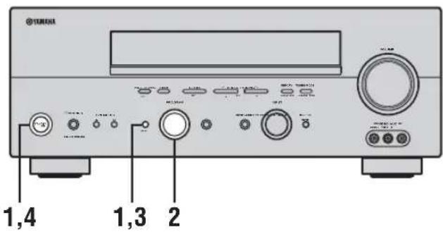
1 Turn off the power to this unit, and while holding down STRAIGHT (EFFECT), press STANDBY/ON.
This unit turns on, and the ADVANCED SETUP menu appears in the front panel display.
STRAIGHT

While holding down, press

2 Rotate PROGRAM on the front panel to move through the menu and select the item you want to set up.
See the end of this section for a complete list of available parameters.

3 Press STRAIGHT (EFFECT) repeatedly to toggle between the available parameters.

4 Press STANDBY/ON to confirm your selection.

This completes the advanced setup procedure. The settings you made are reflected the next time this unit's power is turned on.
■ ADVANCED SETUP menu items
Change the initial settings (indicated in bold under each parameter) to reflect the needs of your listening environment.
Speaker impedance SP I MP.
Use to switch the speaker impedance for this unit.
Choices: 8 Ω MIN, 4 Ω MIN
- Select 8 MIN to set the speaker impedance to 8 .
- Select 4 MIN to set the speaker impedance to 4 .
| SP IMP. | Speaker Impedance | level |
| 4 Ω MIN | Front | If you use one set (A or B), the impedance of each speaker must be 4 Ω or higher. |
| If you use two sets (A and B), the impedance of each speaker must be 8 Ω or higher. | ||
| Center | The impedance of each speaker must be 6 Ω or higher. | |
| Surround | ||
| Surround back | ||
| 8 Ω MIN | Front | If you use one set (A or B), the impedance of each speaker must be 8 Ω or higher. |
| If you use two sets (A and B), the impedance of each speaker must be 16 Ω or higher. | ||
| Center | The impedance of each speaker must be 8 Ω or higher. | |
| Surround | ||
| Surround back |
Factory presets PRESET
Use to reset all parameters to the factory presets (see page 72).
Choices: CANCEL, RESET
- Select CANCEL if you do not want this unit's parameters to be initialized when you reset the factory presets.
- Select RESET if you want all of this unit's parameters to be initialized when you reset the factory presets.
Note
This setting does not affect ADVANCED SETUP menu item parameters.
Remote REMOTE
Use to switch the ID for the remote control of this unit. Choices: ID1, ID2
- Select ID1 to operate this unit using the default code.
- Select ID2 to operate this unit using an alternative code.
Note
You must also make settings for the remote control (see page 60).
REMOTE CONTROL FEATURES
In addition to controlling this unit, the remote control can also operate other A/V components made by YAMAHA and other manufacturers. To control other components, you must set up remote control with the appropriate remote control codes.
Control area
■ Controlling this unit
The shaded areas below can be used to control this unit when the AMP mode is selected. Press AMP to activate the AMP mode.
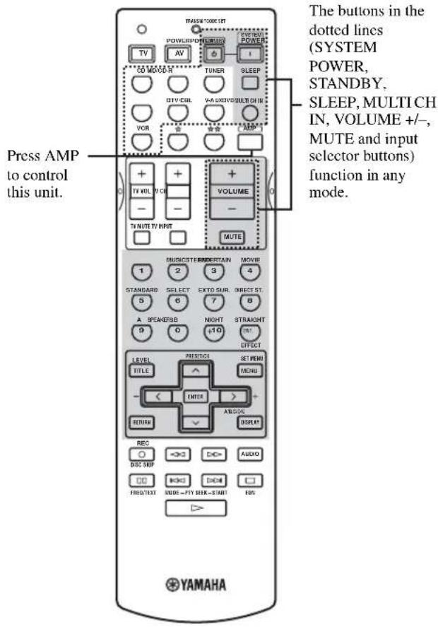
■ Controlling other components
The shaded areas below can be used to control other components. Each button has a different function depending on the selected components. Select the component you want to control by pressing an input selector button.
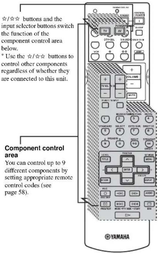
Setting remote control codes
You can control other components by setting the appropriate remote control codes. Codes can be set up for each input area. For a complete list of available remote control codes, refer to "LIST OF REMOTE CONTROL CODES" at the end of this manual.
The following table shows the default component (Library: component category) and the remote control code for each area.
Remote Control Code Default Settings
| Input area | Library (component category) | Manufacturer | Default YAMAHA code |
| CD CD | YAMAHA 0005 | ||
| MD/CD-R | MD YAMAHA 0024 | ||
| TUNER TUNER YAMAHA | 0023*10033*2 | ||
| DVD DVD YAMAHA 0098 | |||
| DTV/CBL- | - | - | |
| V-AUX | - | - | - |
| VCR | - | - | - |
| ☆ | DVR YAMAHA 0208 | ||
| ☆☆ | - | - | - |
*1 U.K. and Europe models
*2 Other models
Note
You may not be able to operate your YAMAHA component even if a YAMAHA remote control code is initially set as listed above. In this case, try to set other YAMAHA remote control code(s).
1 Press an input selector button or ☆/☆☆ to select the component you want to set up.
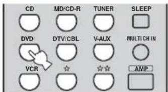
2 Press CODE SET using a ballpoint pen or similar object.
The TRANSMIT indicator on the remote control flashes twice.

3 Press the numeric buttons (0 to 9) to enter the four-digit remote control code for the component to be used.
Refer to "LIST OF REMOTE CONTROL CODES" at the end of this manual.
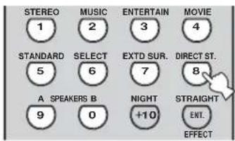
The TRANSMIT indicator on the remote control flashes twice, and the remote control code for the selected component is set.
Notes
- If the manufacturer of your component has more than one code, try each of them until you find the correct one.
- If you wait for more than 30 seconds during step 3, the setup process is canceled. If this happens, start over from step 2.
Controlling other components
Once you set the appropriate remote control codes, you can use this remote to control your other components. Note that some buttons may not correctly operate the selected component. Use the input selector buttons to select the component you want to operate. The remote control automatically switches to the appropriate control mode for that component.
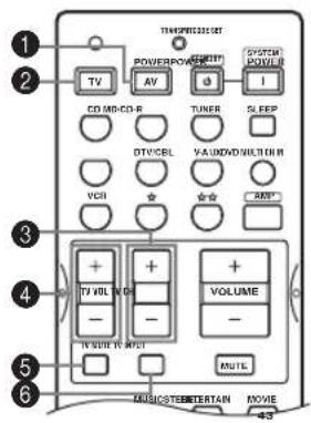
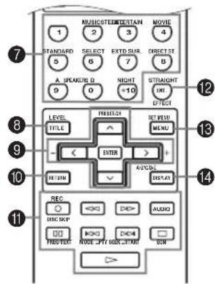
| DVD player/DVD recorder | VCR | Digital TV/Cable TV | CD player | MD/CD recorder Tuner | |||
| 1 | AV POWER | Power *1 | Power *1 | VCR power *3 | Power *1 | Power *1 | Power *1 |
| 2 | TV POWER | TV power *2 | TV power *2 | TV power | TV power *2 | TV power *2 | TV power *2 |
| 3 | TV CII + | TV channel up *2 | TV channel up *2 | TV channel up | TV channel up *2 | TV channel up *2 | TV channel up *2 |
| TV CH - | TV channel down *2 | TV channel down *2 | TV channel down | TV channel down *2 | TV channel down *2 | TV channel down *2 | |
| 4 | TV VOL + | TV volume up *2 | TV volume up *2 | TV volume up | TV volume up *2 | TV volume up *2 | TV volume up *2 |
| TV VOL - | TV volume down *2 | TV volume down *2 | TV volume down | TV volume down *2 | TV volume down *2 | TV volume down *2 | |
| 5 | TV MUTE | TV mute *2 | TV mute *2 | TV mute | TV mute *2 | TV mute *2 | TV mute *2 |
| 6 | TV INPUT | TV input *2 | TV input *2 | TV input | TV input *2 | TV input *2 | TV input *2 |
| 7 | 1-9, 0, +10 | Numeric buttons | Numeric buttons | Numeric buttons | Numeric buttons | Numeric buttons | Preset stations (1-8) |
| 8 | TITLE | Title | |||||
| 9 | PRESET/CH u | Up | VCR channel up | Preset up (1-8) | |||
| PRESET/CH d | Down | VCR channel down | Preset down (1-8) | ||||
| j | Left | ||||||
| i | Right | Preset up (A-E) | |||||
| ENTER | Enter | ||||||
| 0 | RETURN | Return | |||||
| A | REC/DISC SKIP | Disc skip (player)Rec (recorder) | Rec | VCR rec *3 | Disc skip | Rec (MD) | |
| p | Play | Play | VCR play *3 | Play | Play | ||
| w | Search backward | Search backward | VCR searchbackward *3 | Search backward | Search backward | ||
| f | Search forward | Search forward | VCR search forward *3 | Search forward | Search forward | ||
| AUDIO | Audio | ||||||
| e | Pause | Pause | VCR pause *3 | Pause | Pause | ||
| b | Skip backward | Skip backward | Skip backward | ||||
| a | Skip forward | Skip forward | Skip forward | ||||
| s | Stop | Stop | VCR stop *3 | Stop | Stop | ||
| B | ENT. | Title/Index | Enter | Enter | Index | Index | |
| C | MENU | Mcnu | |||||
| D | DISPLAY | Display | Display | Display | Display | ||
*1 This button functions only when the original remote control of the component has a POWER button.
*2 These buttons can operate your TV without switching the input if the remote control code is set in DTV/CBL or ☆☆.
When the remote control code for your TV is set up in both the DTV/CBL and ☆☆ areas, priority is given to the signal in the DTV/CBL area.
*3 These buttons can operate your VCR without switching the input to VCR if the remote control code is set in VCR.
Switching library codes
You can select the unit you want to operate with the remote control by entering the library code.
1 Press CODE SET using a ballpoint pen or similar object.
The TRANSMIT indicator on the remote control flashes twice.

2 Enter the code number "9991" or "9992" (see the table below).
The TRANSMIT indicator on the remote control flashes twice, and the library code is changed.
| AMP library code (remote control setting) | Function | Remote control ID (unit setting, see page 56) |
| 9991 | To operate this unit using the default code. | ID1(initial setting) |
| 9992 | To operate this unit using an alternative code. | ID2 |
When using multiple YAMAHA receivers/amplifiers, you may be able to operate the other components simultaneously with the default code setting. In this case, set one of the alternative codes to operate this unit separately.
Note
You must also make settings for the receiver/amplifier.
Clearing set up remote control codes
1 Press an input selector button or ☆/☆☆ to select the component control for which you want to clear the remote control code.
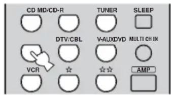
2 Press CODE SET using a ballpoint pen or similar object.
The TRANSMIT indicator on the remote control flashes twice.

3 Enter the code number "0000".
The TRANSMIT indicator on the remote control flashes twice, and the remote control code for the selected component is cleared.
y
- If you do not press any button within 30 seconds after step 2, the clearing process is canceled. If this happens, start over from step 1.
- You can clear all setup remote control codes at once by entering the code number "9990".
ZONE 2
This unit allows you to configure a multi-room audio system. You can control this unit from the second room using the supplied remote control.
Only analog signals are sent to the second room. Any source you want to listen to in the second room must be connected using the analog (AUDIO L/R) input jacks on this unit.
Zone 2 connections
You need the following additional equipment to use the multi-room functions of this unit:
- An infrared signal receiver in the second room.
- An infrared emitter in the main room. This emitter transmits the infrared signals from the remote control in the second room to the main room (to a CD player, for example).
- An amplifier and speakers for the second room.
y
- Since there are many possible ways to connect and use this unit in a multi-room installation, we recommend that you consult with your nearest authorized YAMAHA dealer or service center about the Zone 2 connections that best meet your requirements.
- Some YAMAHA models are able to connect directly to the REMOTE CONTROL OUT jack of this unit. If you own these products, you may not need to use an infrared emitter. Up to 6 YAMAHA components can be connected as shown.
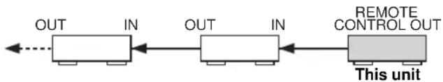
flowchart
graph LR
    A["OUT"] --> B["IN"]
    B --> C["OUT"]
    C --> D["IN"]
    D --> E["REMOTE CONTROL OUT"]
    E --> F["This unit"]
■ System configuration and connections example
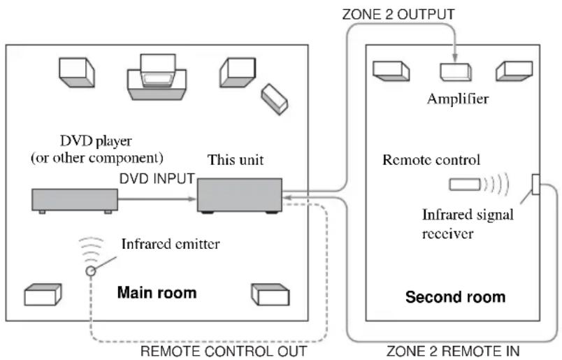
flowchart
graph TD
    A["Main room"] --> B["Infrared emitter"]
    B --> C["DVD INPUT"]
    C --> D["This unit"]
    D --> E["Main room"]
    F["DVD player (or other component)"] --> C
    G["Amplifier"] --> H["Second room"]
    I["Remote control"] --> J["Infrared signal receiver"]
    K["REMOTE CONTROL OUT"] --> D
    L["ZONE 2 OUTPUT"] --> H
    M["ZONE 2 REMOTE IN"] --> H
Notes
- When not using the main room, turn down the volume of this unit in the main room. Adjust the volume control on the amplifier in the second room.
- To avoid unexpected noise, DO NOT USE the Zone 2 feature with CDs encoded in DTS.
Remote controlling Zone 2
The supplied remote control can be used to control Zone 2. You can even select the input source and control components located in the main room directly from the second room regardless of the listening condition in the main room.
y
You can also turn on/off the main or Zone 2 mode by pressing MAIN or ZONE 2 on the front panel.
■ To enable Zone 2 mode on the remote control
1 Press


2 Press CODE SET using a ballpoint pen or similar object.
The TRANSMIT indicator on the remote control flashes twice.

3 Enter the code number "2999".
Immediately after you have configured the remote control for Zone 2, the remote will enter main mode. When the remote is in main mode, you can turn the main unit on, or set it in standby mode independently of Zone 2 by pressing SYSTEM POWER or STANDBY.
Notes
- If you enable Zone 2, the Zone function is applied to the current remote control ID (ID1: default code, ID2: alternative code). However, because the remote control codes for Zone 2 are common to ID1 and ID2, the remote control ID does not change even if it is switched.
- To release ZONE 2, clear the remote control code set for ☆☆, or set a remote control code other than a TV code for ☆☆.
■ To control Zone 2
1 Press to set the remote control to Zone 2.
The TRANSMIT indicator on the remote control lights up while the remote control is in Zone 2 mode.
2 Press SYSTEM POWER to turn Zone 2 power on.
3 Press an input selector button to select the input source you want to listen to in the second room.
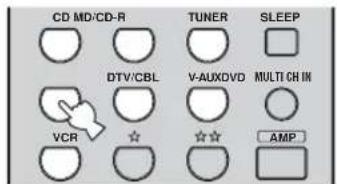
4 You can control Zone 2 using the input selector buttons, STANDBY, SYSTEM POWER and MUTE.
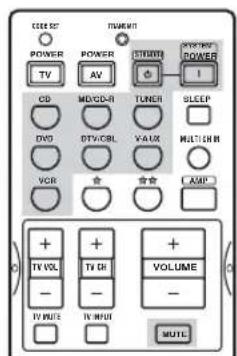
y
Zone 2 volume cannot be adjusted with the remote control. Use the control on the amplifier in the second room.
Note
The remote control returns to the main mode 10 seconds after you press or if you press any button other than SYSTEM POWER, STANDBY, MUTE or the input selector buttons. If the TRANSMIT indicator is turned off, press set the remote control to Zone 2 mode before turning Zone 2 power on or off, changing the input source, or muting the sound.
■ To control the power of the main unit and Zone 2 unit
To turn all units (the main unit and Zone 2 unit) to standby:
While holding down AMP, press STANDBY.
To turn on all units (the main unit and Zone 2 unit):
While holding down AMP, press SYSTEM POWER.
y
STANDBY and SYSTEM POWER work differently depending on the selected mode.
| Mode | TRANSMIT indicator | STANDBY/SYSTEM POWER |
| Main mode Off | Press STANDBY to turn the main unit to standby. | |
| Press SYSTEM POWER to turn on the main unit. | ||
| Zone 2 mode On | Press STANDBY to turn the Zone 2 component to standby. | |
| Press SYSTEM POWER to turn on the Zone 2 component. |
■ Special considerations for DTS software
The DTS signal is a digital bitstream. If you attempt to send the DTS signal to the second room you will only hear digital noise (that may damage your speakers). Thus, the following considerations and adjustments need to be made when playing DTS-encoded discs.
For DVDs encoded in DTS
Only 2 channel analog audio signals may be sent to the second room.
Use the disc menu to set the DVD player's mixed 2-channel left and right audio outputs to the PCM or Dolby Digital soundtrack.
For CDs encoded in DTS
To avoid unexpected noise, DO NOT USE the Zone 2 feature with CDs encoded in DTS.
EDITING SOUND FIELD PARAMETERS
What is a sound field Changing parameter settings
What really creates the rich, full tones of a live instrument are the multiple reflections from the walls of the room. In addition to making the sound “live”, these reflections enable us to tell where the player is situated, and the size and shape of the room in which we are sitting.
■ Elements of a sound field
In any environment, in addition to the direct sound coming straight to our ears from the player's instrument, there are two distinct types of sound reflections that combine to make up the sound field:
Early reflections
Reflected sounds reach our ears extremely rapidly (50 ms – 100 ms after the direct sound), after reflecting from one surface only – for example, from the ceiling or a wall. Early reflections actually add clarity to the direct sound.
Reverberations
These are caused by reflections from more than one surface – walls, ceiling, the back of the room – so numerous that they merge together to form a continuous sonic “afterglow”. They are non-directional, and lessen the clarity of the direct sound.
Direct sound, early reflections and subsequent reverberation taken together help us to determine the subjective size and shape of the room, and it is this information that the digital sound field processor reproduces in order to create sound fields.
If you could create the appropriate early reflections and subsequent reverberations in your listening room, you would be able to create your own listening environment. The acoustics in your room could be changed to those of a concert hall, a dance floor, or virtually any size room at all. This ability to create sound fields at will is exactly what YAMAHA has done with the digital sound field processor.
You can enjoy good quality sound with the factory preset parameters. Although you do not have to change the initial settings, you can change some of the parameters to better suit the input source or your listening room.
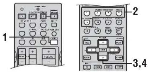
1 Press AMP.

2 Select the sound field program you want to adjust.
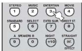
3 Press u /d to select the parameters.
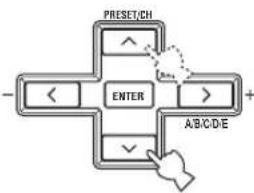
flowchart
graph TD
    A["ENTER"] --> B["PRESET/CH"]
    A --> C[">"]
    A --> D["ABC/D/E"]
    A --> E["<<"]
    A --> F["✓"]
4 Press j / i to change the parameter value.
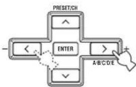
flowchart
graph TD
    A["PRESET/CH"] --> B["ENTER"]
    B --> C["A/B/C/D/E"]
    C --> D["+"]
    B --> E["<<"]
    E --> F["<<"]
    F --> G["<<"]
    G --> H["<<"]
    H --> I["<<"]
    I --> J["<<"]
    J --> K["<<"]
    K --> L["<<"]
    L --> M["<<"]
    M --> N["<<"]
    N --> O["<<"]
    O --> P["<<"]
    P --> Q["<<"]
    Q --> R["<<"]
    R --> S["<<"]
    S --> T["<<"]
    T --> U["<<"]
    U --> V["<<"]
    V --> W["<<"]
    W --> X["<<"]
    X --> Y["<<"]
    Y --> Z["<<"]
    Z --> AA["<<"]
    AA --> AB["<<"]
    AB --> AC["<<"]
    AC --> AD["<<"]
    AD --> AE["<<"]
    AE --> AF["<<"]
    AF --> AG["<<"]
    AG --> AH["<<"]
    AH --> AI["<<"]
    AI --> AJ["<<"]
    AJ --> AK["<<"]
    AK --> AL["<<"]
    AL --> AM["<<"]
    AM --> AN["<<"]
    AN --> AO["<<"]
    AO --> AP["<<"]
    AP --> AQ["<<"]
    AQ --> AR["<<"]
    AR --> AS["<<"]
    AS --> AT["<<"]
    AT --> AU["<<"]
    AU --> AV["<<"]
    AV --> AW["<<"]
    AW --> AX["<<"]
    AX --> AY["<<"]
    AY --> AZ["<<"]
    AZ --> BA["<<"]
    BA --> BB["<<"]
    BB --> BC["<<"]
    BC --> BD["<<"]
    BD --> BE["<<"]
    BE --> BF["<<"]
    BF --> BG["<<"]
    BG --> BH["<<"]
    BH --> BI["<<"]
    BI --> BJ["<<"]
    BJ --> BK["<<"]
    BK --> BL["<<"]
    BL --> BM["<<"]
    BM --> BN["<<"]
    BN --> BO["<<"]
    BO --> BP["<<"]
    BP --> BQ["<<"]
    BQ --> BR["<<"]
    BR --> BS["<<"]
    BS --> BT["<<"]
    BT --> BU["<<"]
    BU --> BV["<<"]
    BV --> BW["<<"]
    BW --> BX["<<"]
    BX --> BY["<<"]
    BY --> BZ["<<"]
    BZ --> CA["<<"]
    CA --> CB["<<"]
    CB --> CC["<<"]
    CC --> CD["<<"]
    CD --> CE["<<"]
    CE --> CF["<<"]
    CF --> CG["<<"]
    CG --> CH["<<"]
    CH --> CI["<<"]
    CI --> CJ["<<"]
    CJ --> CK["<<"]
    CK --> CR["<<"]
    CR --> CS["<<"]
    CS --> CT["<<"]
    CT --> CU["<<"]
    CU --> CV["<<"]
    CV --> CW["<<"]
    CW --> CX["<<"]
    CX --> CY["<<"]
    CY --> CZ["<<"]
y If you press and hold j /i to change the parameter value, the front panel display automatically stops at the factory preset parameter momentarily.
5 Repeat steps 2 through 4 as necessary to change other program parameters.
Note
You cannot change parameter values when "MEMORY GUARD" is set to ON. If you want to change the parameter values, set "MEMORY GUARD" to OFF (see page 53).
Memory back-up
The memory back-up circuit prevents the stored data from being lost even if this unit is set in the standby mode, the power cord is disconnected from the AC outlet, or the power supply is temporarily cut due to power failure. However, if the power is cut for more than one week, the parameter values will return to the factory settings. If this happens, edit the parameter value again.
■ Resetting parameters to the factory presets
Use PARAM. INI (see page 54).
SOUND FIELD PARAMETER DESCRIPTIONS
You can adjust the values of certain digital sound field parameters so the sound fields are recreated accurately in your listening room. Not all of the following parameters are found in every program.
■ DSP LEVEL (DSP level)
Function: Adjusts the level of all the DSP effect sounds within a narrow range.
Description: Depending on the acoustics of your listening room, you may want to increase or decrease the DSP effect level relative to the level of the direct sound.
Control range: -6 dB to +3 dB
■ INIT.DLY (Initial delay)
Function: Changes the apparent distance from the source sound by adjusting the delay between the direct sound and the first reflection heard by the listener.
Description: The smaller the value, the closer the sound source seems to the listener. The larger the value, the farther it seems. For a small room, set to a small value. For a large room, set to a large value.
Control range: 1 to 99 msec
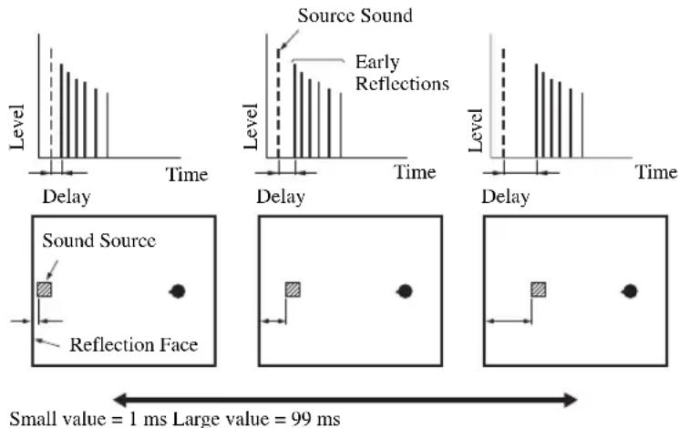
For 2ch Stereo:
■ DIRECT (Direct)
Function: Bypasses this unit's decoders and DSP processors for pure high fidelity sound when playing 2-channel analog sources. The AUTO setting is effective only when BASS and TREBLE are set to 0 dB.
Choices: AUTO, OFF
Notes
- When multi-channel signals (Dolby Digital and DTS) are input, they are downmixed to 2 channels and output from the front left and right speakers.
- When “BASS OUT” is set to BOTH, or “FRONT” set to SMALL and “BASS OUT” set to SWFR, front left and right speaker low-frequency signals are redirected to the subwoofer.
For 6ch Stereo:
Function: These parameters adjust the volume level for each channel in 6-channel stereo mode.
Control range: 0 to 100%
■ CT LEVEL (Center level)
■ SL LEVEL (Surround left level)
■ SR LEVEL (Surround right level)
■ SB LEVEL (Surround back level)
For PRO LOGIC IIx Music and PRO LOGIC II Music:
■ PANORAMA (Panorama)
Function: Sends stereo signals to the surround speakers as well as the front speakers for a wraparound effect.
Choices: OFF, ON
■ DIMENSION (Dimension)
Function: Gradually adjusts the sound field either towards the front or towards the rear.
Control range: -3 (towards the rear) to +3 (towards the front), initial setting is STD (standard).
■ CT WIDTH (Center width)
Function: Adjusts the center image from all three front speakers to varying degrees. A larger value adjusts the center image towards the front left and right speakers.
Control range: 0 (center channel sound is output only from center speaker) to 7 (center channel sound is output only from front left and right speakers)
Initial setting: 3
Note
This parameter can be set only when SUR. STANDARD is selected.
For DTS Neo:6 Music:
■ C. IMAGE (Center image)
Function: Adjusts the center image from all three front speakers to varying degrees.
Control range: 0 to 1.0
Initial setting: 0.3
Note
This parameter can be set only when SUR. STANDARD is selected.
TROUBLESHOOTING
Refer to the chart below when this unit does not function properly. If the problem you are experiencing is not listed below or if the instruction below does not help, set this unit to the standby mode, disconnect the power cord, and contact the nearest authorized YAMAHA dealer or service center.
■ General
| Problem Cause | Remedy | Refer to page | |
| This unit fails to turn on when STANDBY/ON (or SYSTEM POWER) is pressed, or enters the standby mode soon after the power has been turned on. | The power cord is not connected or the plug is not completely inserted. | Connect the power cord firmly. | — |
| The impedance setting is incorrect. Set the impedance to match your speakers. | 56 | ||
| The protection circuitry has been activated. | Make sure all speaker wire connections on this unit and on all speakers are secure and that the wire for each connection does not touch anything other than its respective connection. | 11-13 | |
| This unit has been exposed to a strong external electric shock (such as lightning or strong static electricity). | Set this unit in the standby mode, disconnect the power cord, plug it back in after 30 seconds, then use it normally. | — | |
| No sound Incorrect input or output cable connections. | Connect the cables properly. If the problem persists, the cables may be defective. | 14-20 | |
| The input mode is set to DTS or ANALOG. | Select AUTO. | ||
| No appropriate input source has been selected. | Select an appropriate input source with INPUT, MULTI CH INPUT (or MULTI CH IN on the remote control) or the input selector buttons. | ||
| Speaker connections are not secure. Secure the connections. | |||
| The front speakers to be used have not been selected properly. | Select the front speakers with SPEAKERS A and/or B. | ||
| The volume is turned down. Turn up the volume. | |||
| The sound is muted. Press MUTE or any operation button of this unit to resume audio output, then adjust the volume. | |||
| The input mode is set to ANALOG while playing a source encoded with a DTS signal. | Set the input mode to AUTO or DTS. | ||
| Signals this unit cannot reproduce are being received from a source component, such as a CD-ROM. | Play a source whose signals can be reproduced by this unit. | ||
| No picture The output and input for the picture are connected to different types of video jacks. | Turn on the video conversion function. | 53 | |
| The sound suddenly goes off. | The protection circuitry has been activated because of a short circuit, etc. | Check that the impedance selector setting is correct. | 56 |
| Check that the speaker wires are not touching each other and then turn this unit back on. | — | ||
| The sleep timer has turned the unit off. Turn on the power, and play the source again. | — | ||
| The sound is muted. Press MUTE to cancel a mute. | 26 | ||
| Only the speaker on one side can be heard. | Incorrect cable connections. Connect the cables properly. If the problem persists, the cables may be defective. | 12 | |
| Incorrect balance settings in SET MENU. Adjust the SP LEVEL settings. | 51 | ||
| Only the center speaker outputs substantial sound. | When playing a monaural source with a CINEMA DSP program, the source signal is directed to the center channel, and the front and surround speakers output effect sounds. | ||
| No sound from the effect speakers. | The sound field programs are turned off. Press STRAIGHT (EFFECT) to turn them on. | 31 | |
| You are using a source or program combination that does not output sound from all channels. | Try another sound field program. | 27, 43 | |
| No sound from the center speaker. | The output level of the center speaker is set to minimum. | Raise the level of the center speaker. | 51 |
| “CENTER” in SET MENU is set to NONE. | Select the appropriate setting for the center speaker. | 50 | |
| One of the HiFi DSP programs (except for 6ch Stereo) has been selected. | Try another sound field program. | 27, 43 | |
| No sound from the surround speakers. | The output level of the surround speakers is set to minimum. | Raise the output level of the surround speakers. | 51 |
| “SUR. LR” in SET MENU is set to NONE. | Select the appropriate setting for the surround left and right speakers. | 50 | |
| A monaural source is being played with STRAIGHT. | Press STRAIGHT (EFFECT) to turn on the sound fields. | — | |
| No sound from the surround back speaker. | “SUR. LR” in SET MENU is set to NONE. | If the surround left and right speakers are set to NONE, the surround back speaker setting is automatically set to NONE. Select the appropriate setting for the surround speakers. | 50 |
| “SUR. B” in SET MENU is set to NONE. Select LRG or SML. | 50 | ||
| No sound from the subwoofer. | “BASS OUT” in SET MENU is set to FRONT when a Dolby Digital or DTS signal is being played. | Select SWFR or BOTH. | 50 |
| “BASS OUT” in SET MENU is set to SWFR or FRONT when a 2-channel source is being played. | Select BOTH. | 50 | |
| The source does not contain low bass signals. | |||
| Dolby Digital or DTS sources cannot be played. (Dolby Digital or DTS indicator in the front panel display does not light up.) | The connected component is not set to output Dolby Digital or DTS digital signals. | Make an appropriate setting following the operating instructions for your component. | — |
| The input mode is set to ANALOG. Set the | input mode to AUTO or DTS. | 32 | |
| A “humming” sound can be heard. | Incorrect cable connections. Firmly connect | the audio plugs. If the problem persists, the cables may be defective. | — |
| The volume level cannot be increased, or the sound is distorted. | The component connected to the OUT (REC) jacks of this unit is turned off. | Turn on the power to the component. | — |
| The sound effect cannot be recorded. | It is not possible to record the sound effect with a recording component. | ||
| A source cannot be recorded by a digital recording component connected to this DIGITAL OUTPUT jack. | The source component is not connected to this unit's DIGITAL INPUT jacks. | Connect the source component to the DIGITAL INPUT jacks. | 14-18 |
| Some components cannot record the Dolby Digital or DTS sources. | |||
| A source cannot be recorded by an analog component connected to the AUDIO OUT jacks. | The source component is not connected to this unit's analog AUDIO IN jacks. | Connect the source component to the analog AUDIO IN jacks. | 14-18 |
| The sound field parameters and some other settings on this unit cannot be changed. | “MEMORY GUARD” in SET MENU is set to ON. | Select OFF. | 53 |
| This unit does not operate properly. | The internal microcomputer has been frozen by an external electric shock (such as lightning or excessive static electricity) or by a power supply with low voltage. | Disconnect the AC power cord from the outlet and then plug it in again after about 30 seconds. | — |
| “CHECK SP WIRES” appears in the front panel display. | Speaker cables are short circuited. Make sure all speaker cables are connected correctly. | 12 | |
| There is noise interference from digital or radio frequency equipment, or this unit. | This unit is too close to the digital or high-frequency equipment. | Move this unit further away from such equipment. | — |
| The picture is disturbed. | The video source uses scrambled or encoded signals to prevent dubbing. | ||
| This unit suddenly turns into the standby mode. | The internal temperature becomes too high and the overheat protection circuitry has been activated. | Wait about 1 hour for this unit to cool down and then turn it back on. | — |
■ Tuner
| Problem Cause Remedy | Refer to page | |||
| FM | FM stereo reception is noisy. | The characteristics of FM stereo broadcasts may cause this problem when the transmitter is too far away or the antenna input is poor. | Check the antenna connections.Try using a high-quality directional FM antenna. | 19 |
| Use the manual tuning method. | 34 | |||
| There is distortion, and clear reception cannot be obtained even with a good FM antenna. | There is multipath interference. Adjust the antenna position to eliminate multipath interference. | — | ||
| The desired station cannot be tuned in with the automatic tuning method. | The signal is too weak. Use a high-quality directional FM antenna. | 19 | ||
| 34 | ||||
| Previously preset stations can no longer be tuned in. | This unit has been disconnected for a long period. | Preset the stations again. | 34 | |
| AM | The desired station cannot be tuned in with the automatic tuning method. | The signal is weak or the antenna connections are loose. | Tighten the AM loop antenna connections and orient it for the best reception. | — |
| Use the manual tuning method. | 34 | |||
| There are continuous crackling and hissing noises. | Noises result from lightning, fluorescent lamps, motors, thermostats and other electrical equipment. | Use an outdoor antenna and a ground wire.This will help somewhat, but it is difficult to eliminate all noise. | — | |
| There are buzzing and whining noises. | A TV set is being used nearby. Move this unit away from the TV. | — | ||
■ Remote control
| Problem Cause | Remedy | Refer to page | |
| The remote control does not work nor function properly. | Wrong distance or angle. The remote control | will function within a maximum range of 6 m and no more than 30 degrees off-axis from the front panel. | 7 |
| Direct sunlight or lighting (from an inverter type of fluorescent lamp, etc.) is striking the remote control sensor of this unit. | Reposition this unit. | — | |
| The batteries are weak. Replace all batteries. | 3 | ||
| The remote control code was not correctly set. | Set the remote control code correctly using “LIST OF REMOTE CONTROL CODES” at the end of this manual. | 58 | |
| Try to set another code for the same manufacturer using “LIST OF REMOTE CONTROL CODES” at the end of this manual. | 58 | ||
| The remote control ID and this unit’s ID do not match. | Switch the library code. | 60 | |
| Even if the remote control code is correctly set, there are some models that do not respond to the remote control. |
RESETTING THE FACTORY PRESETS
If you want to reset all of your unit's parameters for any reason, do the following. This procedure completely resets ALL parameters, including the SET MENU, level, assign and tuner presets.
Be sure this unit is in standby mode.
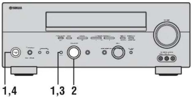
1 With the unit in standby mode, hold down STRAIGHT (EFFECT) on the front panel and press STANDBY/ON.
The ADVANCED SETUP menu appears in the front panel display.

While holding down, press

y To cancel the initialization procedure without making any changes, press STANDBY/ON.
2 Rotate PROGRAM to move through the menu and select "PRESET".

3 Press STRAIGHT (EFFECT) to select the desired setting.

RESET To reset the unit to its factory presets. CANCEL To cancel without making any changes.
4 Press STANDBY/ON to confirm your selection.
If you selected "RESET", the unit is reset to its factory presets and switches to standby mode. If you selected "CANCEL", the unit switches to standby mode and nothing is reset.
GLOSSARY
Audio formats
■ Dolby Digital
Dolby Digital is a digital surround sound system that gives you completely independent multi-channel audio. With 3 front channels (left, center, and right), and 2 surround stereo channels, Dolby Digital provides 5 full-range audio channels. With an additional channel especially for bass effects, called LFE (low frequency effect), the system has a total of 5.1-channels (LFE is counted as 0.1 channel). By using 2-channel stereo for the surround speakers, more accurate moving sound effects and surround sound environment are possible than with Dolby Surround. The wide dynamic range (from maximum to minimum volume) reproduced by the 5 full-range channels and the precise sound orientation generated using digital sound processing provide listeners with previously unheard of excitement and realism.
With this unit, any sound environment from monaural up to a 5.1-channel configuration can be freely selected for your enjoyment.
■ Dolby Digital EX
Dolby Digital EX creates 6 full-bandwidth output channels from 5.1-channel sources. This is done using a matrix decoder that derives 3 surround channels from the 2 in the original recording. For the best results, Dolby Digital EX should be used with movie sound tracks recorded with Dolby Digital Surround EX. With this additional channel, you can experience more dynamic and realistic moving sound especially with scenes with “flyover” and “fly-around” effects.
■ Dolby Pro Logic II
Dolby Pro Logic II is an improved technique used to decode vast numbers of existing Dolby Surround software. This new technology enables a discrete 5-channel playback with 2 front left and right channels, 1 center channel, and 2 surround left and right channels (instead of only 1 surround channel for conventional Pro Logic technology). Music and Game modes are also available for 2-channel sources in addition to the Movie mode.
■ Dolby Pro Logic IIx
Dolby Pro Logic IIx is a new technology enabling discrete multi-channel playback from 2-channel or multi-channel sources. There is a Music mode for music, a Movie mode for movies (for 2-channel sources only) and a Game mode for games.
■ Dolby Surround
Dolby Surround uses a 4 channel analog recording system to reproduce realistic and dynamic sound effects: 2 front left and right channels (stereo), a center channel for dialog (monaural), and a surround channel for special sound effects (monaural). The surround channel reproduces sound within a narrow frequency range.
Dolby Surround is widely used with nearly all video tapes and laser discs, and in many TV and cable broadcasts as well. The Dolby Pro Logic decoder built into this unit employs a digital signal processing system that automatically stabilizes the volume on each channel to enhance moving sound effects and directionality.
■ DTS 96/24
DTS 96/24 offers an unprecedented level of audio quality for multi-channel sound on DVD-Video, and is fully backward-compatible with all DTS decoders. "96" refers to a 96 kHz sampling rate (compared to the typical 48 kHz sampling rate). "24" refers to 24-bit word length. DTS 96/24 offers sound quality transparent to the original 96/24 master, and 96/24 5.1-channel sound with full-quality full-motion video for music programs and motion picture soundtracks on DVD-video.
■ DTS (Digital Theater Systems) Digital Surround
DTS digital surround was developed to replace the analog soundtracks of movies with a 6-channel digital sound track, and is now rapidly gaining popularity in movie theaters around the world. Digital Theater Systems Inc. has developed a home theater system so that you can enjoy the depth of sound and natural spatial representation of DTS digital surround in your home. This system produces practically distortion-free 6-channel sound (technically, a left, right and center channels, 2 surround channels, plus an LFE 0.1 channel as a subwoofer, for a total of 5.1-channels). The unit incorporates a DTS-ES decoder that enables 6.1-channel reproduction by adding the surround back channel to existing 5.1-channel format.
■ Neo:6
Neo:6 decodes the conventional 2-channel sources for 6 channel playback by the specific decoder. It enables playback with the full-range channels with higher separation just like digital discrete signal playback. Two modes are available; “Music mode” for playing music sources and “Cinema mode” for movies.
Sound field programs Audio information
■ CINEMA DSP
Since the Dolby Surround and DTS systems were originally designed for use in movie theaters, their effect is best felt in a theater having many speakers and designed for acoustic effects. Since home conditions, such as room size, wall material, number of speakers, and so on, can differ so widely, it's inevitable that there are differences in the sound heard as well. Based on a wealth of actually measured data, YAMAHA CINEMA DSP uses YAMAHA original sound field technology to combine Dolby Pro Logic, Dolby Digital and DTS systems to provide the visual and audio experience of movie theater in the listening room of your own home.
■ SILENT CINEMA
YAMAHA has developed a natural, realistic sound effect DSP algorithm for headphones.
Parameters for headphones have been set for each sound field so that accurate representations of all the sound field programs can be enjoyed on headphones.
■ Virtual CINEMA DSP
YAMAHA has developed a Virtual CINEMA DSP algorithm that allows you to enjoy DSP sound field surround effects even without any surround speakers by using virtual surround speakers.
It is even possible to enjoy Virtual CINEMA DSP using a minimal two-speaker system that does not include a center speaker.
ITU-R
ITU-R is the radio communication sector of the ITU (International Telecommunication Union). ITU-R recommends a standard speaker placement which is used in many critical listening rooms, especially for mastering purposes.
■ LFE 0.1 channel
This channel is for the reproduction of low bass signals. The frequency range for this channel is 20 Hz to 120 Hz. This channel is counted as 0.1 because it only enforces a low frequency range compared to the full-range reproduced by the other 5/6 channels in Dolby Digital or DTS 5.1/6.1-channel systems.
■ PCM (Linear PCM)
Linear PCM is a signal format under which an analog audio signal is digitized, recorded and transmitted without using any compression. This is used as a method of recording CDs and DVD audio. The PCM system uses a technique for sampling the size of the analog signal per very small unit of time. Standing for “pulse code modulation”, the analog signal is encoded as pulses and then modulated for recording.
■ Sampling frequency and number of quantized bits
When digitizing an analog audio signal, the number of times the signal is sampled per second is called the sampling frequency, while the degree of fineness when converting the sound level into a numeric value is called the number of quantized bits.
The range of rates that can be played back is determined based on the sampling rate, while the dynamic range representing the sound level difference is determined by the number of quantized bits. In principle, the higher the sampling frequency, the wider the range of frequencies that can be played back, and the higher the number of quantized bits, the more finely the sound level can be reproduced.
Video signal information
■ Component video signal
With the component video signal system, the video signal is separated into the Y signal for the luminance and the P_B and P_R signals for the chrominance. Color can be reproduced more faithfully with this system because each of these signals is independent. The component signal is also called the “color difference signal” because the luminance signal is subtracted from the color signal. A monitor with component input jacks is required in order to use the component signal for output.
■ Composite video signal
With the composite video signal system, the video signal is composed of three basic elements of a video picture; color, brightness and synchronization data. A composite video jack on a video component transmits these three elements combined.
■ S-video signal
With the S-video signal system, the video signal normally transmitted using a pin cable is separated and transmitted as the Y signal for the luminance and the C signal for the chrominance through the S-video cable. Using the S VIDEO jack eliminates video signal transmission loss and allows recording and playback of even more beautiful images.
SPECIFICATIONS
AUDIO SECTION
- Minimum RMS Output Power for Front, Center, Surround, Surround back 20 Hz to 20 kHz, 0.06% THD, 8 Ω....90 W
• Maximum Power (EIAJ) [Asia, Korea and General models] 1 kHz, 10% THD, 8 Ω ..... 130 W
• Dynamic Power (IHF) 8/6/4/2 Ω 120/155/190/235 W
• DIN Standard Output Power [U.K. and Europe models] 1 kHz, 0.7% THD, 4 Ω ..... 135 W
- IEC Output Power [U.K. and Europe models] 1 kHz, 0.06% THD, 8 Ω .... 100 W
- Damping Factor (IHF) 20 Hz to 20 kHz, 8 Ω ....120 or more
- Frequency Response CD terminal to Front L/R 10 Hz to 100 kHz, -3 dB
- Total Harmonic Distortion CD, etc. to Front L/R (20 Hz to 20 kHz, 40 W, 8 Ω) 0.06% or less
- Signal to Noise Ratio (IHF-A Network) CD (250 mV) to Front L/R, Effect Off ....100 dB or more
- Residual Noise (IHF-A Network) Front L/R 150 μV or less
- Channel Separation (1 kHz/10 kHz) CD (5.1 kΩ terminated) to Front L/R ..... 60 dB/45 dB or more
- Tone Control (Front L/R) BASS Boost/Cut ....±10 dB/60 Hz TREBLE Boost/Cut ....±10 dB/20 kHz
- Phones Output 150 mV/100 Ω
- Input Sensitivity/Input Impedance CD, etc. 200 mV/47 kΩ MULTI CH INPUT 200 mV/47 kΩ
- Output Level/Output Impedance REC OUT.... 200 mV/1.2 kΩ SUBWOOFER .... 4 V/1.2 kΩ ZONE 2 OUTPUT [U.S.A., Canada, Australia, U.K. and Europe models] .... 200 mV/1.2 kΩ
VIDEO SECTION
- Video Signal Type PAL/NTSC
- Signal to Noise Ratio 50 dB or more
- Frequency Response (MONITOR OUT) Composite, S-video .... 5 Hz to 10 MHz, -3 dB Component .... 5 Hz to 60 MHz, -3 dB
FM SECTION
- Tuning Range [U.S.A. and Canada models] .... 87.5 to 107.9 MHz [Asia and General models] .... 87.5/87.50 to 108.0/108.00 MHz [Other models] .... 87.50 to 108.00 MHz
- Usable Sensitivity (IHF).... 1.0 μV (11.2 dBf)
- Signal to Noise Ratio (IHF) Mono/Stereo 76 dB/70 dB
• Harmonic Distortion (1 kHz) Mono/Sterco 0.2%/0.3%
- Stereo Separation (1 kHz) 42 dB
• Frequency Response ...... 20 Hz to 15 kHz, +0.5, -2 dB
AM SECTION
- Tuning Range [U.S.A. and Canada models] .... 530 to 1710 kHz [Asia and General models] .... 530/531 to 1710/1611 kHz [Other models] .... 531 to 1611 kHz
- Usable Sensitivity 300 μV/m
GENERAL
• Power Supply [U.S.A. and Canada models] ..... AC 120 V, 60 Hz [Australia model] ..... AC 240 V, 50 Hz [Korea model] ..... AC 220 V, 60 Hz [U.K. and Europe models] ..... AC 230 V, 50 Hz [General model] ..... AC 110/120/220/230–240 V, 50/60 Hz [Asia model] ..... AC 220/230–240 V, 50/60 Hz
• Power Consumption [U.S.A. and Canada models] .... 350 W/440 VA [Other models] .... 360 W
- Standby Power Consumption 0.1 W or less
- AC Outlets [U.K. and Australia models] .... 1 (Total 100 W maximum) [U.S.A. and Canada models] .... 2 (Total 100 W maximum) [Europe, Asia and General models] .... 2 (Total 50 W maximum)
- Dimensions (W x H x D).... 435 x 171 x 420 mm
• Weight 11 kg
ATTENTION: VEUILLEZ LIRE CE QUI SUIT AVANT D'UTILISER L'APPAREIL.
Raccordements Zone 2 ....61
Piles (4)
(AAA, R03, UM-4)

natural_image
Line drawing of four cylindrical batteries with battery caps (no text or symbols)5 Prises REMOTE IN/OUT
0 Prise SUBWOOFER OUTPUT
flowchart
graph TD
    A["Screen with monitor icon"] --> B["Section with grid and box"]
    B --> C["Component with 3D structure and arrow indicating assembly"]
    C --> D["Final Component with bracket and arrow indicating assembly"]
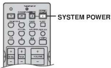
■ EON (Enhanced Other Networks)
Choix: meters (m), feet (ft)
Choix: MAX (maximum), STD (standard), MIN (minimum)
Enceinte SP D. R
Raccordements Zone 2
1 Appuyez sur AMP.

■ DIMENSION (Dimension)
natural_image
Illustration of four cylindrical batteries with battery terminals (no text or symbols)UKW-Zimmerantenne

MW-Rahmenantenne
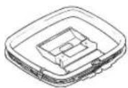
flowchart
graph TD
    A["Screen with monitor"] --> B["Internal component"]
    B --> C["Base with attached components"]
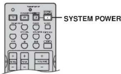
Ton-Bypass TC. BYPASS
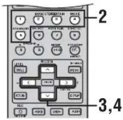
1 Drücken Sie AMP.

■ DIMENSION (Dimension)
■ CT WIDTH (Center-Breite)
Surround: 90 W + 90 W
Bakre surround: 90 W
Ljudfältsegenskaper
◆ Patentskyddad YAMAHA-teknik för att skapa ljudfält
◆ Dolby Digital/Dolby Digital EX-decoder
◆ DTS/DTS-ES Matrix 6.1-, Discrete 6.1-, DTS Neo:6-, DTS 96/24-dekoder
◆ Dolby Pro Logic/Dolby Pro Logic II/Dolby Pro Logic IIx-dekoder
◆ Virtual CINEMA DSP
◆ SILENT CINEMA™
Sofistikerad AM/FM-tuner
Batterier (4)
(AAA, R03, UM-4)

natural_image
Line drawing of four cylindrical batteries with battery caps (no text or symbols)FM-inomhusantenn

AM-ramantenn
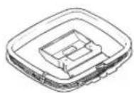
7 DIGITAL INPUT-koppling
HÖGTALARINSTALLATION
Högtalarnas placering
flowchart
graph TD
    A["Front Panel"] --> B["Top Panel"]
    B --> C["Bottom Panel"]
    C --> D["Mounting System"]

1 Tryck på AMP.

■ EON (Enhanced Other Networks)
Alternativ: meters (m), feet (ft)
Alternative: MD/CD-R, CD, V-AUX, DTV/CBL, VCR, DVD
flowchart
graph LR
    A["OUT"] --> B["IN"]
    B --> C["OUT"]
    C --> D["IN"]
    D --> E["REMOTE CONTROL OUT"]
    E --> F["Receive"]
■ DIMENSION (dimension)
natural_image
Line drawing of four cylindrical batteries with battery caps (no text or symbols)FM binnenantenne

AM ringantenne
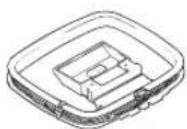
flowchart
graph TD
    A["Screen with monitor icon"] --> B["Device with internal structure"]
    B --> C["Printer with base panel"]
    C --> D["Final package with clamping mechanism"]
STANDBY/ON
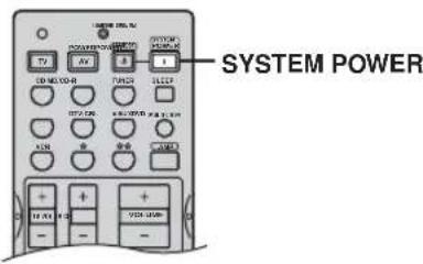
■ Afstandsbediening
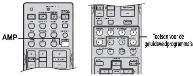
3 Houd MEMORY (MAN'L/AUTO FM) tenminste 3 seconden ingedrukt.
flowchart
graph TD
    A["MODE - PTY SEEK - START"] --> B["PTY HOLD"]
    B --> C["Licht op"]
y
Keuzes: meters (m), feet (ft)
Keuzes: MAX (maximum), STD (standard), MIN (minimum)
Luidspreker SP D. R
Keuzes: [A] DVD, DTV/CBL, V-AUX, VCR [B] DVD, DTV/CBL, V-AUX, VCR
Keuzes: 8 Ω MIN, 4 Ω MIN
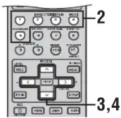
1 Druk op AMP.

natural_image
Illustration of four cylindrical batteries with battery terminals (no text or symbols)Рамочная АМ-антенна
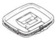
flowchart
graph TD
    A["Screen with monitor"] --> B["Internal structure with grid"]
    B --> C["Computer with base"]
    C --> D["Assembly of base component"]
STANDBY/ON
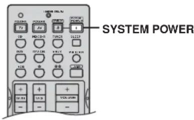
Выбор: meters (m), feet (ft)
Для гнезд OPTICAL INPUT 2 (I N (2)), 3 (I N (3)) и 4 (I N (4))
Выбор: (2) CD, MD/CD-R, DVD, DTV/CBL, V-AUX, VCR (3) CD, MD/CD-R, DVD, DTV/CBL, V-AUX, VCR (4) CD, MD/CD-R, DVD, DTV/CBL, V-AUX, VCR
Для гнезда 5 COAXIAL INPUT (I N (5))
GBC 0021, 0141, 1321,
1511, 1621, 1981
GEC 0451, 1101, 1281, 2321
GEC (UK) 0031, 0081, 0581, 0601, 1101, 1281, 1561
GELOSO 0021, 0411, 0451, 1321, 1511, 1621, 1981
GENERAL TECHNIC
2681
GENEXXA 0451, 1331
GOODMANS 0141, 1101, 1371, 1641, 2301
GORENJE 0981, 1061
0451
GRANADA 0141, 0451, 0491, 0581, 0601, 1101, 1111, 1351, 1981, 2321
GRANADA (UK) 0081, 0141, 0451, 0491, 0581, 0601, 1031, 1311, 1521, 1561, 1641
GRUNDIG 0221, 0231, 0471, 0491, 0711, 0741, 1381, 2021, 2041, 2141, 2151
HANSEATIC 0021, 0121, 0141, 0431, 0591, 1561
HANTAREX 0581
HEMMERMANN 0061
HIFIVOX 0331, 0571
HINARI 0071, 0141, 0451, 1261, 1351, 1511, 1641, 1981, 2011
HITACHI 0001, 0011, 0031, 0081, 0141, 0291, 0331, 0341, 0451, 0601, 0631, 0701, 1281, 1561, 1601, 1821, 1831, 1841, 1861, 1871, 1881, 1891, 1941, 1981, 2051, 2321, 2341
HYPER 0591,0601,1511, 1621
IMPERIAL 0451, 0491, 0811, 0981, 1401, 1611, 1621, 2201, 2251, 2271
INGERSOL 1511
INNO HIT 0581, 0601, 0841, 1101, 1331, 1371, 1511, 2011
INNOVATION 2591, 2601, 2611, 2621, 2641, 2651, 2661, 2711, 2721, 2761, 2771, 2781
INTERFUNK 0031, 0041, 0061, 0121, 0181, 0451, 0491, 1081, 1641, 1791, 1821, 1981, 2231
IRRADIO 0491, 1321, 1331, 1371, 1411, 1511, 2011
ISUKAI 1331
ITT 0031, 0041, 0051, 0061, 0071, 0081, 0181, 0411, 0451, 0491, 1241, 1291, 1351, 1501, 1601, 1641, 1741, 1921, 1981, 2091, 2331, 2431
ITT-NOKIA 0031, 0041, 0051, 0061, 0071, 0081, 0181, 0411, 0451, 0491, 1241, 1291, 1351, 1501, 1601, 1641, 1741, 1921, 1981, 2091, 2331, 2431
JVC 0071, 0721, 1441, 1581, 1591, 1741, 1791
KAISUI 0591, 1321, 1331
KAMOSONIC 0601
KARCHER 0591, 0601, 0841, 1091, 1321, 1511, 1561, 2051
KAWASHO 0761
KENDO 0261
KENNEDY 0021, 0351, 0951, 1981
KONKA 2701
| KORTING 0431, 1011, 1021,1081, 1541 | MURPHY | 0451, 2091 | PRANDONI-PRINCE | SCOTT 1171, 1261 | |
| MURPHY (UK) | 0081, 1031 | 0411, 0451, 0491,0581, 1411 | SEG | 0261, 0601, 0821,0991 | |
| KTV 0601, 1171 | N.E.I. | 0101, 0961 | |||
| LENOIR 0601, 1511 | NAD 1341 | PRANDONI-PROMCE | SEI | 0641, 0691, 1081,1301, 1481, 1981 | |
| LEYEO 1181 | NEC | 0141, 1711, 1721,1731 | 0451, 0491, 0581 | SELECO | 0071, 0101, 0351,0411, 0451, 0951,1901, 2061, 2101,2111 |
| LG (GOLDSTAR) 0591, 0601,0761, 0791, 1371,1491, 1511, 1561,1621, 1641 | NECKERMANN | 0451, 0601,0981, 1081, 1561,1931, 1981, 2211,2231, 2241 | PROTECH 0641, 1181, 1981QUELLE 0041, 0061, 0121,0221, 0231, 0391,0491, 0521, 0601,0781, 1371, 1381,1411, 1421, 1641,1681, 2051, 2091,2141, 2151, 2201,2211, 2231, 2241,2251, 2271, 2551,2571, 2581 | SENTRA 1601SHARP | 0141, 0151, 0191,1761, 1781SIAREM0021, 0261, 0581,0641, 1021, 1081,1981 |
| LIFETEC 2591, 2601, 2611,2621, 2641, 2651,2661, 2671, 2681,2691, 2711, 2761,2771, 2781 | NEDIATOR | 0101 | |||
| NICAMAGIC | 0761 | ||||
| NIKKAI | 1101, 1331, 1641,1701, 2011 | ||||
| LOEWE OPTA 0121, 0131,0581, 0611, 1081 | NOBLIKO | 0261, 0491, 0591,0641, 1381, 1411 | SICATEL 1971SIEMENS | 0151, 0221, 0231,0451, 0741, 2011,2201, 2211, 2221,2231, 2241, 2261,2571, 2581 | |
| LOGIC 1691, 2281 | NOGAMATIC | 0571 | |||
| LOGIK 0551, 1681, 2281 | NOKIA | 0031, 0041, 0051,0061, 0071, 0081,0181, 0411, 0451,0491, 1241, 1291,1351, 1501, 1601,1641, 1741, 1921,1981, 2091, 2331,2431, 2461, 2791 | RADIOMARELLI0101, 0451,0661, 0771, 1081RADIONETTE0031, 2051,2091 | SILVER | 0151, 0221, 0231,0451, 0741, 2011,2201, 2211, 2221,2231, 2241, 2261,2571, 2581 |
| LOWEWE 0831 | |||||
| LUMA 0351, 0451, 1901 | |||||
| LUXMAN 0791 | |||||
| LUXMAN STEREO TUNER0791 | |||||
| LUXOR 0001, 0061, 0181,0341, 0421, 0451,0461, 0491, 0601,0671, 1351, 1371,1561, 1601, 1911,1921, 1981 | NORDMENDE | 0031, 0291,0331, 0451, 0531,0541, 0571, 1051,1131, 1591, 1791,1811, 1821, 1891,1941, 2631 | RANK0481, 2151RBM2131, 2151RBM (UK)0481REDIFFUSION0451, 0661,1641, 1981, 2331REDIFFUSION(UK)0061, 0081, 1031REX0071, 0101, 0351,0411, 0451, 0951,1901, 2061, 2101,2111 | SINUDYNE0021, 0061, 0101,0261, 0391, 0641,0691, 0851, 0941,1021, 1081, 1241,1301, 1321, 1481,1631, 1981 | SKANTIC0451SOLAVOX0101, 1641, 2011SONOKO0101, 1181, 1511SONY0141, 0171, 1121,1681, 1691, 2751 |
| LYCO 1181 | |||||
| MAGNADYNE 0021, 0061,0261, 0581, 0641,0771, 1021, 1081,1621, 1981 | OCEANIC 0321, 1651, 1981OCEANIC (F) | 0031, 0061, 0321,0441, 1661 | RFT0991, 2511ROADSTAR1321, 1511ROTEL0151SABA0291, 0331, 0421,0451, 0531, 0541,0571, 0581, 0651,0731, 0931, 1021,1071, 1081, 1131,1791, 1811, 1821,1891, 1941, 2631 | SOUNDESIGNSSSSTERN | 04510451, 1641, 20110101, 1181, 1511211SUNKAISUPRA0791TANDBERG0161, 0331, 0611,1021, 1421, 1771,1791, 2081 |
| MAGNAFON 0261, 0491, 0581,0591, 0641, 0761,1091, 2001 | ONCEAS 0601 | ||||
| ONWA | 1171 | ||||
| ORION | 0061, 0391, 0691,0851, 1211, 1241,1251, 1301, 1481,1511, 1681, 1691,1981, 2371, 2421 | SACCSSAISHO0451, 0601, 1161,1241, 1301, 1511,1671, 1681, 1691 | TANDY | 0191, 0451, 1331,1531 | |
| MANESTH0101 | |||||
| MARANTZ 0101 | |||||
| MARELLI 1081 | |||||
| MARK0101 | |||||
| MATSUI 0061, 0451, 0601,0691, 1101, 1151,1241, 1271, 1301,1511, 1561, 1681,1691 | OSAKA 2011OSAKI 1101, 1331, 2011OSUME0151OTTO VERSAND0021, 0121,0141, 0221, 0601,1561, 1741, 1981 | SALORA 0011, 0041, 0061,0071, 0341, 0451,0671, 1291, 1351,1521, 1561, 1601,1641, 1911, 1921,1931, 1981, 2321 | TASHIKO | 0141TATUNG 0271, 0581, 0601,0971, 1101, 1681,1691 | |
| MAXIMAL0071, 1981 | |||||
| MCMICHAEL 1281 | PAEL | 0591, 1411 | |||
| MEDION 2591, 2601, 2611,2621, 2641, 2651,2661, 2671, 2681,2691, 2711, 2721,2761, 2771, 2781 | PANASONIC | 0031, 0201, 0211,0451, 0701, 1311,1751, 1961, 2561,2741 | SAMBERS0261, 0491, 0581,0641, 1091, 1371,1411, 2001 | TECHNICS | 0311, 0551, 0731,1131, 1471, 1591, |
| MEMOREX 1511 | PANORAMIC | 2351 | |||
| METZ0231, 0741, 1001,1041, 1081, 1481,2071, 2081 | PATHE MARCONI | 0571 | |||
| PATHE CINEMA (F) | 0431, 0591, 1621,1661, 1971 | SAMSUNG0101, 0601, 0841,0981, 1101, 1181,1371, 1511, 2011 | TELE | TELEAVIA0571, 0651, 0731,1821 | |
| MGA 1231 | PAUSA | 1511 | |||
| MICROMAXX 2591, 2621, 2641,2651, 2711, 2761,2771, 2781 | PAUZA | 1511 | |||
| PERDIO | 0891, 1101 | ||||
| PHILCO | 0021, 0491, 0811,0981, 1021, 1081,1401, 1611, 1621,1751, 2201, 2251,2271, 2451, 2471 | SANYO 0141, 0151, 0401,0601, 0801, 0821,0981, 1021, 1101,1111, 1291, 1351,1691, 1741, 2051,2091, 2551 | TELEFUNKEN | 0291, 0301,0311, 0551, 0731,1131, 1471, 1591, | |
| MINERVA 0221, 0231, 0491,1381, 2141, 2151 | |||||
| MISTRAL 2281 | |||||
| MITSUBISHI0141, 0201, 0231,0661, 1191, 1201,1231, 1671, 1691,1741 | PHILIPS 0101, 0361, 0591,0621, 0681, 0751,0761, 1021, 1081,1281, 2031, 2281 | SBR | 0681, 0751, 1281,2281 | TELETECH | 0311, 0551, 0731, |
| MIVAR0491, 0501, 0581,0591, 0761, 0771,1371, 1431, 2031 | PHOENIX 1081 | SCHAUB LORENZ0451 | TELETECH | TELEAVIA | 0311, 0551, 0731, |
| MOLTITECH 0261, 0581, 0601,0641, 0981, 1321,1511 | PHONOLA0751, 1081 | SCHNEIDER0021, 0071, 0091,0451, 0511, 0591, | TEMPEST 2381 | TELEAVIA | 0391, 2401,241 |
| PIONEER | 0291, 0451, 1341,182 | SCHAUB LORENZ | TELETECH | TELEAVIA | |
| THOMSON 0331, 0481, 0531,0571, 0631, 0651,0731, 0901, 1241,1571, 1591, 1791,1811, 1821, 1891,1941, 2531 | |
| THORN 0741, 0861, 2091,2251, 2271, 2281 | |
| THORN-FERGUSON | |
| 0281, 0371, 0551,0651, 0781, 0861,0881, 1131, 1181,1361, 1461, 1971,1991, 2281 | |
| TMK 0141, 0791, 1471 | |
| TOSHIBA 0141, 0381, 0481,1221, 1271, 1701,1741, 1851, 2151,2801, 2811 | |
| TRANS CONTINENS | |
| 0451 | |
| TRISTAR 2281 | |
| TRIUMPH 0481, 0581, 2121 | |
| UHER 0431, 0451, 0481,0491, 0511, 1311,1541 | |
| ULTRAVOX 0021, 0261, 0591,1021, 1081, 1981 | |
| UNIVERSUM 1181, 2051 | |
| UNIVOX 1971 | |
| VEGAVOX 0811 | |
| VEXA 0101, 1511 | |
| VICTOR 1441, 1591 | |
| VIDEOTON 2481 | |
| VORTEC 0101, 0651 | |
| VOXSON 0411, 0451, 0491,1021, 1081 | |
| WALTHAM 0451 | |
| WATSON 0431, 2201, 2241 | |
| WATT RADIO 0021, 0061, 0261,0591, 0641, 0761,1091, 1971, 1981,2001 | |
| WEGA 0141, 1081, 1981 | |
| WEGA COLOR 1021 | |
| WELTBLICK 0101 | |
| WESTON 1621 | |
| WHITE WESTINGHOUSE | |
| 0101, 0261, 0431,0591, 0761, 1401,1541 | |
| YAMAHA 2821, 2831, 2841,2851 | |
| YOKO 0601, 1511 | |
| ZANUSSI 0071, 0101, 0351,0411, 0451, 0951,1901, 2061, 2101,2111 | |
| ZOPPAS 0451 |
CABLE TV
| CABLETIME | 1446, 1456, 1476 |
| CLYDE CABLEVISION | |
| 1426 | |
| FILMNET | 1396, 1436 |
| FRANCE TELECOM | |
| 1386 | |
| GEC | 1426 |
| JERROLD | 1416 |
| MOVIE TIME | 1466 |
| NSC | 1466 |
| PHILIPS | 1386 |
| PIONEER | 0006 |
| SAMSUNG | 1496 |
| SCIENTIFIC ATLANTA | |
| 1486, 1506 | |
| STARCOM 1416 | |
| STS | 1466 |
| TANDBERG | 1366 |
| TELE | 1436 |
| TELE +1 1436 | |
| TELESERVICE | 1406, 1476 |
| TUDI | 1376 |
| UNITED CABLE 1416 | |
| ZENITH | 1406 |
SATELLITE TUNER
| AKAI | 1276 |
| ALBA 0826, 1276 | |
| AMSTRAD | 0166, 0796, 1016, 1026, 1296 |
ANKARO 0476
| AST | 0406 |
| ASTRA | 0126 |
| BARCOM | 0476 |
| BLAUPUNKT | 0966 |
| BMC SATELLITE | 0106 |
| BRITISH TELECOM | 1276 |
| BUSH | 0826 |
| BUSH (UK) | 0956 |
| CAMBRIDGE | 0196, 1276 |
| CANAL PLUS (FRANCE) | |
1530 CHAPARRAL 0016, 0696, 1006
| COLUMBUS 0616 | |
| CONNEXIONS | 0306, 0426 |
| DISCUS ELIPSE | 0856, 0866 |
| DISKXPRESS 0426, 0476 | |
| DRAKE 1516 | |
| ECHOSTAR 0226, 0236, 0606,0626, 0666, 0926,0996, 1046, 1056,1066, 1106 | |
| ELTA | 1286 |
| ELTA SAT | 0146 |
| EURODEC | 1226, 1236, 1246 |
| FERGUSON | 0046, 0176, 0186, 0296, 0846, 0956, 1306 |
| FINLUX | 0976 |
| FRACARRO | 0026, 0536, 0776 |
| FUBA | 0476, 0616, 0636, 1056 |
| GIUCAR RECORD | 0206, 0336 |
| GRUNDIG | 0176, 0946, 0956, 0966 |
| HIGH PERFORMANCE | |
| 0916 | |
| HIRSCHMANN | 0756, 0966 |
| HITACHI | 0446, 0516, 0706, 0946 |
| ICX INTERNATIONAL | |
| 0886 | |
| ITT | 0066, 0126, 0176, 0446, 1156 |
| ITT/NOKIA | 0066, 0126, 0176, 0446, 1156 |
| JEEMON | 0146 |
| JERROLD | 0846, 0986 |
| JOHANSSON | 0246 |
| JVC | 1276 |
| KATHREIN | 0116, 0266, 0276, 0366, 1586 |
| KOSMOS | 0266 |
| KYOSTAR | 1036, 1086 |
| LENG | 0246 |
| LIFESAT 1326, 1346, 1356 | |
| LUXOR 0126, 0136, 0446,0466, 0506, 1156 |
| MACAB | 0356 |
| MASPRO 0016, 0116, 0256, 0956 | |
| MEDION | 1326, 1346 |
| METZ 0966 |
| MICROMAXX 1326, 1346 |
| MITSUBISHI | 0966 |
| MORGANS | 0596 |
| MURATTO | 0406 |
| NEC | 0286, 0316, 0766, 0786, 0836 |
| NETWORK | 0046 |
| NIKKO | 1136, 1146 |
| NOKIA | 0066, 0126, 0176, 0446, 1156, 1166, 1336 |
NORSAT 0786
| OTTO VERSAND | 0966 |
| PACE | 0046, 0176, 0296,0936, 0956, 1306,1566, 1576 |
PACE MSS 0946
| PACE SKY DIGITAL BOX (UK) |
| 1526 |
| PALCOM 0616, 0686, 0706 |
| PALSAT | 0396 |
| PALTEC | 0706 |
| PANASONIC | 0806, 1306 |
| PANSAT | 1076 |
| PHILIPS | 0326, 0346, 0476, 0956, 1126, 1186, 1196, 1206, 1216, 1306, 1316 |
| PROSAT | 1176 |
| PTT TELECOM | 0306, 0896 |
| QUELLE 0966 |
| RADIX | 1056 |
| REDIFFUSION | 0316, 0786 |
| RFT | 1186, 1196, 1206, 1216 |
| SAGEM | 1256, 1546 |
| SAKURA 0566.0816 |
| SALORA | 0066, 0126, 0136, 0446, 0456, 0486, 0496, 0576 |
| SAMSUNG | 0746, 0756 |
| SAT | 0406 |
| SATCOM | 0896 |
| SATECO | 0646 |
| SECTOR | 1266 |
| SEDEA | 1096 |
SENTRA 0416
| SIEMENS 0896, 0966 |
| SINTRACK 0906 |
| SKYLAB | 0476 |
| SKYSCAN | 0876 |
| SONY 0736, 0946 |
STELLA 0306
| STRONG | 0156, 0396, 1036, 1086 |
| STV | 0636 |
| TANDBERG | 1116 |
| TANDY | 0916 |
| TANTEC | 0616 |
| TATUNG 0516, 0546 |
| TECHNISAT | 0086, 0096, 0526, 0556, 1056 |
TELECOM 0306
| TELEMAX | 0586 |
| THORN-FERGUSON |
| 0046, 0076, 0176, |
| 0186, 0956 |
TOSHIBA 0946
TPS (FRANCE) 1546
| TRIAD | 0406 |
| UNIDEN | 0036, 0216, 0676, 0716, 0726 |
US ELECTRONICS 0886
| VORTEC 0756, 1036, 1076 |
VTECH 0436
| WINERSAT | 0246 |
| WISI | 0056, 0356, 0376,0386, 0406, 0656,1056, 1156 |
WOLSEY 0916
| XCOM MULTIMEDIA1556 |
XSAT (FRANCE) 1556
| ZEHNDER | 0266, 0406 |
| ZENDER | 0406 |
VCR
| AIWA | 0042, 0352, 0432 |
| AKAI | 0042, 0422, 0492, 0582, 0612, 0642, 0652, 0762, 0912 |
| ALBA 0002, 0112, 0282,0332, 0342, 0972 |
AMSTRAD 0322, 0432, 0452
| ANITECH | 0002 |
ANITSCH 1002
| ASA | 0012, 0052 |
| AUDIOSONIC | 0002 |
BAIRD 0042, 0282, 0492
| BANG & OLUFSEN 0042 |
BAUR 0052,0062,0812
| BLAUPUNKT | 0062, 0092, 0252, 0462, 0672, 0992 |
BRIONVEGA 0032
| BUSH | 0002, 0282, 0332, 0342, 0512, 0972 |
BUSH (UK) 0812
| CAPEHART 0112 |
CGE 0042, 0432, 0762
| CRAIG | 0072, 0482 |
CROWN 0112,0282,0622
| DAEWOO | 0112, 0282, 0622 |
| DANSAI 0012 |
DAYTRON 0112
| DECCA | 0042, 0052, 0432, 0942 |
DECCA (UK) 0052
| DEGRAAF 0052, 0132, 0432, 0532, 0602 |
DIXI 0442
DUAL 0042, 0632
| DUMONT | 0052, 0432, 0532 |
DYNATECH 0432
| DYNATRON | 0012 |
ELBE 0122
| ELIN | 0072 |
| EMERSON | 0012, 0162, 0202, 0432, 0512, 0522 |
ERRES 0012
| FERGUSON | 0042, 0712, 0722, 0852, 0902, 1012, 1022, 1082 |
FIDELITY 0432
FINLANDIA 0052, 0532
| FINLUX | 0012, 0042, 0052, 0082, 0262, 0382, 0432, 0462, 0492, 0532, 0572, 0602, |
0912
FIRST LINE 0002, 0912
| FISHER 0162, 0482, 0532,0542, 0572, 0592 | |
| FORMENTI-PHOENIX | |
| 0012, 0052 | |
| FRONTECH 0112 | |
| FUNAI 0432 | |
| GBC 0002 | |
| GEC (UK) 0022, 0052 | |
| GELOSO 0002 | |
| GENERAL TECHNIC | |
| 1172 | |
| GOODMANS 0002, 0072, 0282,0432, 0502 | |
| GOODMANS (UK) 0002 | |
| GRAETZ 0022, 0042 | |
| GRANADA 0052, 0132, 0532,0572 | |
| GRANADA (UK) 0052, 0092,0462, 0602, 0812,0822 | |
| GRUNDIG 0052, 0062, 0092,0232, 0252, 0262,0752, 0802 | |
| HANSEATIC 0052, 0812 | |
| HARMAN/KARDON | |
| 0122, 0922 | |
| HCM 0002 | |
| HINARI 0002, 0202, 0412,0442, 0522 | |
| HITACHI 0042, 0172, 0292,0432, 0602, 0662,0812, 1022 | |
| IMPERIAL 0072, 0432 | |
| INGERSOL 0442 | |
| INNO HIT | 0002, 0052, 0072 |
| INNOVATION | 1142, 1162, 1172 |
| INTERFUNK | 0022, 0052 |
| IRRADIO | 0002, 0012 |
| ITT | 0022, 0032, 0042,0072, 0292, 0492,0532, 0572, 0762 |
| ITT-NOKIA | 0022, 0032, 0042,0072, 0292, 0492,0532, 0572, 0762 |
| JENSEN | 0042 |
| JVC (VICTOR) | 0042, 0102,0142, 0272, 0742,0762, 0782, 0902 |
| KARCHER 0052, 0072, 0812 | |
| KENDO 0492 | |
| KENWOOD | 0042, 0142, 0572 |
| LG (GOLDSTAR) | 0012, 0122,0812, 0952 |
| LIFETEC 1142, 1162, 1172 | |
| LLOYD | 0432 |
| LOEWE OPTA | 0052, 0092,0152 |
| LOGIK | 0002, 0072, 0442 |
| LUMA | 0162 |
| LUXOR | 0492, 0572, 0812 |
| M ELECTRONIC | 0432 |
| MAGNADYNE | 0052 |
| MAGNASONIC | 0572 |
| MANESTH | 0012 |
| MARANTZ 0012, 0052, 0092,0122, 0502 | |
| MARK | 0012 |
| MARTA | 0012 |
| MATSUI | 0012, 0442, 0512,0522, 0812, 0972 |
| MEDION 1142, 1162, 1172 | |
| MEMOREX | 0012, 0132, 0432,0482, 0532, 0572 |
| METZ | 0062, 0092, 0932 |
| MGA | 0912 |
| MICROMAXX | 1142, 1162, 1172 |
| MINERVA | 0062, 0092, 0252 |
| MINOLTA | 0172, 0602 |
| MITSUBISHI | 0052, 0062, 0142, 0912, 0922 |
| MTC | 0072, 0432 |
| MULTITECH | 0002, 0052, 0062, 0282, 0432 |
| MURPHY | 0432 |
| N.E.I. | 0012, 0052 |
| NATIONAL | 0462 |
| NEC | 0042, 0122, 0142 |
| NECKERMANN | 0032, 0042, 0052, 0072, 0092, 0202, 0522, 0572, 0762, 0812 |
| NIKKAI | 0112 |
| NOBLIKO | 0092 |
| NOKIA | 0022, 0032, 0042, 0072, 0292, 0492, 0532, 0572, 0762, 1152 |
| NORDMENDE | 0042, 0102, 0142, 0192, 0222, 0242, 0392, 0402, 0632, 0732, 0742, 0762, 0782, 0792, 0832, 0842, 0872 |
| OLYMPUS | 0462 |
| OPTONICA | 0132, 0502 |
| ORION | 0162, 0202, 0312, 0442, 0512, 0522 |
| OSAKA | 0432 |
| OSAKI 0002, 0012, 0432 | |
| OTTO VERSAND | 0052, 0062, 0812 |
| PANASONIC | 0022, 0212, 0462, 0672, 0992, 1092, 1102, 1182 |
| PENTAX | 0172, 0602 |
| PERDIO | 0432 |
| PHILCO | 1062 |
| PHILIPS | 0052, 0082, 0092, 0152, 0182, 0362, 0372, 0382, 0472, 0502, 1072 |
| PHONOLA | 0052, 0152 |
| PILOT | 0012 |
| PIONEER | 0052, 0142, 0372, 0472 |
| PORTLAND | 0112 |
| PROLINE | 0432 |
| PYE | 0052, 0152 |
| QUARTZ 0572 | |
| QUELLE | 0012, 0032, 0042, 0052, 0062, 0072, 0092, 0202, 0462, 0522, 0942 |
| RADIONETTE | 0022 |
| REALISTIC | 0012, 0072, 0132, 0432, 0482, 0502, 0532, 0572 |
| RET | 1072 |
| REX | 0042, 0742, 0782 |
| RICOH | 0952 |
| SABA | 0042, 0142, 0192, 0222, 0242, 0392, 0632, 0732, 0742, 0762, 0772, 0782, 0792, 0872 |
| SAISHO | 0162, 0202, 0292, 0442, 0512, 0522, 0972 |
| SALORA 0192, | 0572, 0812, 0822, 0912 |
| SAMSUNG | 0052, 0072, 0622, 0652, 1192 |
| SANSUI | 0042, 0142 |
| SANYO | 0482, 0532, 0562, 0572 |
| SBR | 0052, 0152, 0182 |
| SCHAUB LORENZ | 0022, 0042 |
| SCHNEIDER | 0002, 0012, 0052, 0072, 0432 |
| SEG | 0002, 0072 |
| SEI-SINUDYNE | 0442 |
| SELECO | 0042 |
| SENTRA | 0112 |
| SHARP | 0132, 0502, 0702 |
| SHINTOM 0002 | |
| SIEMENS | 0062, 0092, 0252, 0572 |
| SINUDYNE | 0052, 0382, 0442, 0932 |
| SONOKO | 0282 |
| SONY | 0432, 0552, 0682, 0692, 0942, 0952, 0962, 1122, 1132 |
| STS | 0602 |
| SUNKAI | 0512 |
| SUNSTAR | 0432 |
| SYLVANIA | 0432, 0912 |
| SYMPHONIC | 0432, 0912 |
| TANDBERG | 0062, 0162, 0522, 0932 |
| TASHIKO | 0132, 0432 |
| TATUNG | 0042, 0052, 0432, 0922 |
| TCM | 1142, 1162, 1172 |
| TEAC | 0042, 0432 |
| TECHNICS | 0462 |
| TEKNIKA | 0012, 0432 |
| TELEFUNKEN | 0042, 0192, 0632, 0732, 0742, 0762, 0782, 0882, 0892 |
| TEMPEST | 1032, 1042, 1052 |
| TENOSAL 0002 | |
| THOMSON 0042, 0102, 0142, 0192, 0402, 0632, 0762 | |
| THORN | 0042, 0902 |
| THORN-FERGUSON | |
| 0042, 0222, 0302, 0712, 0722, 0742, 0762, 0852, 0862, 0872, 0902 | |
| TMK | 0522 |
| TONSAI | 0002 |
| TOSHIBA | 0042, 0622, 0912 |
| TOTEVISION | 0012, 0072 |
| TRIUMPH | 0922 |
| UHER | 0042, 0072 |
| ULTRAVOX | 0032 |
| UNITECH | 0072 |
| VECTOR RESEARCH | |
| 0122 | |
| VICTOR | 0042, 0102, 0142 |
| VIDEON | 1162, 1172 |
| WELTBLICK | 0012 |
| WHITE WESTINGHOUSE | |
| 0032 | |
| XENON 0162 | |
| YAMAHA | 0042, 1202 |
| YOKO | 0012, 0062, 0072 |
| HITACHI 0198 | |
| JVC | 0088, 0178 |
| KENWOOD | 0148 |
| LG | 0228 |
| MAGNAVOX | 0128 |
| MITSUBISHI | 0138 |
| ONKYO | 0068, 0128 |
| PANASONIC | 0028 |
| PHILIPS | 0098, 0128 |
| PIONEER | 0108, 0118 |
| PROSCAN 0158 | |
| RCA 0158 | |
| SAMSUNG | 0078 |
| SHARP | 0038 |
| SONY | 0018 |
| TECHNICS | 0028 |
| THOMSON 0168 | |
| TOSHIBA | 0048, 0128 |
| YAMAHA 0008, 0028, 0098 | |
| ZENITH | 0128 |
DVD RECORDER
| PANASONIC 0238, 0248, 0258 | |
| PHILIPS | 0208 |
| PIONEER | 0278, 0288, 0298 |
| SHARP | 0338, 0348 |
| SONY | 0308, 0318, 0328 |
| TOSHIBA | 0268 |
| YAMAHA | 0208 |
LD PLAYER
| AIWA | 0137 |
| FUNAI 0137 | |
| HITACHI 0047 | |
| MAGNAVOX | 0077 |
| PANASONIC 0027 | |
| PIONEER | 0037 |
| RCA 0067 | |
| REALISTIC | 0137 |
| SAMSUNG | 0017, 0087 |
| SONY | 0057, 0097, 0107, 0117 |
| VICTOR | 0127 |
| YAMAHA | 0007 |
CD PLAYER
| ACCUPHASE | 0315 |
| ADC | 0865 |
| ADCOM | 0785, 1015 |
| AKAI | 0115, 0125, 0725, 0735, 0745, 0935, 1155 |
| ARCAM | 1875 |
| ARCAM-ROTEL | 0165 |
| AUDIO-TECHNICA | 0835 |
| AUDIOSONIC | 0155 |
| AIWA | 1105, 1235, 1245, 1765, 1915, 1935 |
| BSR | 0875 |
| CALIFORNIA | AUDIO LAB 1075 |
| CARRERA | 0555, 0875 |
| CARVER | 0825, 1415 |
| CYRUS-ROTEL | 0205 |
| DENON | 0045, 0955, 1045, 1595, 1795, 1805 |
| DUAL | 1005 |
| ELIN | 0185 |
| EMERSON | 1015, 1285, 1675 |
| FISHER | 0105, 0595, 0605, 0825, 1165, 1175 |
| GENEXXA 0525, 0825, 0855,0875, 0995, 1265,1285, 1345, 1355,1485, 1575, 1675,1715, 1825 | ROTEL | 1875 | PHILIPS | 0134, 0144, 0154 | |
| SABA | 1005 | PIONEER | 0034, 0114 | ||
| SAE | 1875 | SONY | 0094, 0104 | ||
| SALORA 0185 | YAMAHA | 0004, 0014 | |||
| SANSUI | 0415, 0965, 0975,0985, 1255, 1675,1875 | ||||
| GRUNDIG 0175HARMAN KARDON | |||||
| 0325, 0495, 0565,1135, 1145, 1155 | SANYO | 0625, 0825, 0845,0915 | |||
| HITACHI 0065, 0585, 0685,0945, 1005, 1015,1225, 1545 | SCHNEIDER | 1845, 1855 | |||
| SCOTT | 1285, 1675 | ||||
| SHARP | 0025, 0035, 1025,1115, 1275, 1635,1785, 1815, 1825,1835 | ||||
| INNOVATION 1995, 2005, 2015ITT-NOKIA 0185JVC 0385, 0395, 0455,0575, 0585 | |||||
| SHERWOOD | 1275, 1445 | ||||
| KARCHER 0485KENWOOD 0025, 0055, 0145,0215, 0595, 0675,0695, 0705, 0715,0925, 1355, 1485,1575, 1675, 1715,1825 | SIEMENS | 1085 | |||
| SIGNATURE | 1155 | ||||
| SONY | 0345, 0355, 0365,0375, 0865, 1685,1695, 1705, 1715,1725, 1735, 1745 | ||||
| SYLVANIA | 1875 | ||||
| KORTING 0175LG (GOLDSTAR) 0555, 1185,1195, 1585 | TANDBERG | 1885 | |||
| TASHIKO | 1525 | ||||
| TCM | 1985, 2015 | ||||
| LIFETEC 2015LIGHT CONTROL 1155, 1645,1655, 1665 | TEAC | 0235, 0245, 1275,1365, 1375, 1395,1435, 1465, 1475 | |||
| LINN 0165, 1875LUXMAN 0265, 0275, 0795,0805, 1295, 1305,1555, 1925 | TECHNICS | 0465, 0475, 1065,1075, 1625 | |||
| TELEFUNKEN | 1005 | ||||
| THETA DIGITAL | 1865 | ||||
| LUXOR MAGNAVOX MARANTZ 0165, 0175, 0545,0665, 1275, 1335,1405, 1505, 1875,1955 | THOMSON 1005 | ||||
| TOSHIBA | 0755, 0765 | ||||
| VECTOR RESEARCH | |||||
| 0555, 0865 | |||||
| VICTOR | 0575 | ||||
| YAMAHA | 0005, 0015, 0085,0345, 0615, 0655,0815, 0835, 0895,1815 | ||||
| MATSUSHITA MCS MEDION 0075, 1995, 2005,2015 | |||||
| MEMOREX MGA MICROMAXX NAD NAKAMICHI NEC NECKERMAN NIKKO OCEANIC OKANO ONKYO PANASONIC PHILIPS PIONEER JVC 0185 0155, 0225 0885, 1385, 1425,1455, 1515 | MD RECORDER | ||||
| KENWOOD 0214 | |||||
| PIONEER | 0254 | ||||
| SHARP | 0264 | ||||
| SONY | 0224 | ||||
| YAMAHA | 0024, 0224, 0234,0344 | ||||
| TAPE DECK | |||||
| AKAI | 0124 | ||||
| DENON | 0204 | ||||
| GRUNDIG 0134 | |||||
| HARMAN | 0044 | ||||
| JVC 0194 | |||||
| KENWOOD 0164 | |||||
| PROTON QUASAR RADIOLA RADIOTONE REALISTIC | KORTING 0134 | ||||
| LUXMAN 0054, 0064, 0074,0084 | |||||
| MARANTZ 0134, 0144 | |||||
| NAD | 0174 | ||||
| ONKYO | 0184 | ||||

YAMAHA
© 2005 YAMAHA CORPORATION All rights reserved.


