
42.26 - Car radio Macrom - Free user manual and instructions
Find the device manual for free 42.26 Macrom in PDF.



| Product Type | Car audio power amplifier |
| Model | 42.26 (variant of models 42.15/42.17) |
| Brand | Macrom |
| Stereo output power (max) | 70 W x 2 (42.15) / 100 W x 2 (42.17) |
| Bridged output power (max) | 150 W (42.15) / 200 W (42.17) at 4 ohms |
| RMS stereo power (4 ohms, 1 kHz, 1% THD) | 45 W x 2 (42.15) / 65 W x 2 (42.17) |
| RMS stereo power (4 ohms, 20 Hz-20 kHz, 0.05% THD) | 35 W x 2 (42.15) / 50 W x 2 (42.17) |
| Speaker impedance stereo | 4 or 2 ohms |
| Speaker impedance bridged | 4 ohms |
| Frequency response | 10 Hz - 50 kHz (+0/-1 dB) |
| Signal-to-noise ratio | 105 dB (IHF A-weighted) |
| Input sensitivity | 500 mV (center position), adjustable from 100 mV to 2 V |
| Input impedance | 10 kOhms |
| Power supply | 14 V DC (11-16 V tolerant), negative ground |
| Fuse | 20/25 A |
| Net weight | 1.3 kg (42.15) / 1.5 kg (42.17) |
| Dimensions (W x D x H) | Approximately 200 x 150 x 50 mm (estimation) |
| Protections | Soft start, overheat, output short circuit |
| Input connectors | Gold-plated RCA |
| Power connectors | Professional gold-plated screw terminals |
| Speaker connectors | Gold-plated screw terminals |
| Power supply type | MOSFET |
| Power supply filter | Capacitive/inductive for RF interference reduction |
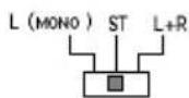
| Input mode | Selector: STEREO, L-MONO, L+R |
Frequently Asked Questions - 42.26 Macrom
User questions about 42.26 Macrom
0 question about this device. Answer the ones you know or ask your own.
Ask a new question about this device
Download the instructions for your Car radio in PDF format for free! Find your manual 42.26 - Macrom and take your electronic device back in hand. On this page are published all the documents necessary for the use of your device. 42.26 by Macrom.
USER MANUAL 42.26 Macrom
natural_image
Abstract black geometric shapes on white background (no text or symbols)CONTENTS / INHALT / TABLE DE MATIERES / INDICE
• INSTALLATION / EINBAU / INSTALLATION / INSTALLAZIONE / INSTALACION .... 3
• CONTROLS AND INDICATORS / BEDIENUNGSELEMENTE UND ANZEIGEN / COMMNDES ET INDICATEURES / CONTROLLI E INDICATORI / CONTROLES E INDICATORES 4
• CONNECTIONS / ANSCHLUSSE / CONNEXIONS / COLLEGAMENTI / CONEXIONES 4
- SYSTEM CHART / SYSTEM-DIAGRAMM / EXAMPLES DE SYSTEME / DIAGRAMMA DI SISTEMA / DIAGRAMA DEL SISTEMA 5-6
"ENGLISH"
INTRODUCTION 7
PRECAUTIONS 7
FEATURES 8-9
CONTROLS AND INDICATORS 9
INSTALLATION 9
CONNECTIONS 10
REGULATION AND SWITCH 11
TECHNICAL DATA 12
" DEUTSCH "
CONNECTIONS / ANSCHLUSSE / CONNEXIONS COLLEGAMENTI / CONEXIONES
Fig. 3./ Abb. 3.
SYSTEM DIAGRAM / SYSTEM-DIAGRAMM / EXEMPLES DE SYSTEME DIAGRAMMA DI SISTEMA / DIAGRAMA DEL SISTEMA
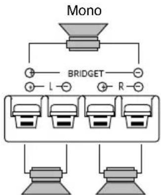
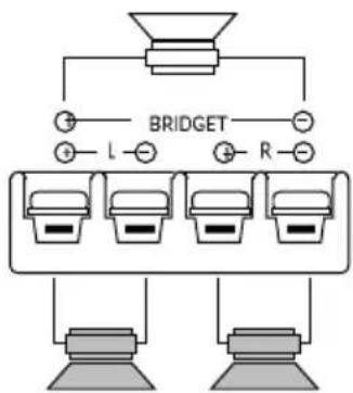
3-CHANNEL CONFIGURATION
Left channel
Right channel

flowchart
graph TD
    A["Mono"] --> B["BRIDGET"]
    B --> C["L"]
    B --> D["R"]
    C --> E["Output"]
    D --> F["Output"]
Left Right
2-CHANNEL CONFIGURATION
Left channel
Right channel

Left Right
1-CHANNEL CONFIGURATION
Left channel
Note: For the other channel another amplifier must to be used in same way.

SYSTEM CHART / SYSTEM-DIAGRAMM / EXEMPLES DE SYSTEME DIAGRAMMA DI SISTEMA / DIAGRAMA DEL SISTEMA
Two channel configuration
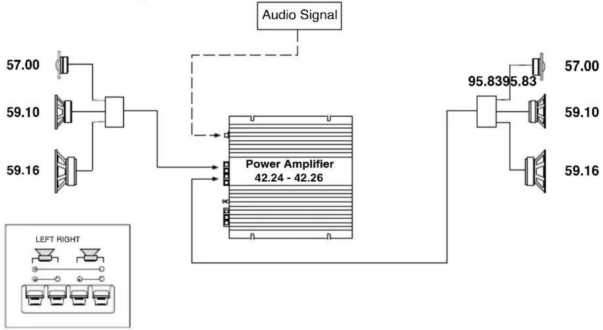
flowchart
graph TD
    A["57.00"] --> B["Speaker 1"]
    C["59.10"] --> D["Speaker 2"]
    E["59.16"] --> F["Speaker 3"]
    B --> G["Power Amplifier 42.24 - 42.26"]
    D --> G
    F --> G
    G --> H["Audio Signal"]
    H --> I["Speaker 1"]
    I --> J["Speaker 2"]
    J --> K["Speaker 3"]
    K --> L["Speaker 4"]
    M["LEFT RIGHT"] --> N["Speaker 1"]
    O["Left Right"] --> P["Speaker 2"]
    Q["Left Right"] --> R["Speaker 3"]
Three channel passive configuration
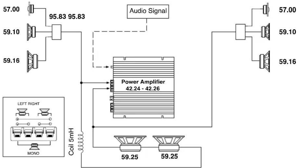
flowchart
graph TD
    A["Speaker 57.00"] --> B["95.83 95.83"]
    C["Speaker 59.10"] --> B
    D["Speaker 59.16"] --> B
    B --> E["Audio Signal"]
    E --> F["Power Amplifier 42.24 - 42.26"]
    F --> G["Coil 5mH"]
    G --> H["Left Right MONO"]
    F --> I["59.25"]
    F --> J["59.25"]
    F --> K["57.00"]
    F --> L["59.10"]
    F --> M["59.16"]
INTRODUCTION
For us at MACROM the achievement of the best sound quality is one of our greatest concerns. In buying the Digital Ready amplifier MACROM 42.24/42.26 we realize that this is also your concern. This unit offers 60/80 Watt max. per channel at 4 Ohm or 125/156 Watt max. when mono-bridged with pure and stable sound qualities.
This instruction manual has been prepared in order to help you to make the most of the outstanding performances and the advanced features and functions of your new amp.
We advise you to read these instructions carefully to familialise yourself with all the special feature of your 42.24/42.26
Please report any problem to your nearest MACROM dealer.
PRECAUTIONS
- The unit may be damaged by wrong lead connection, therefore read carefully the instructions of this manual for the correct connection of the leads.
- The last lead to be connected is the one to the positive (+) terminal of the battery; connect this lead only after having completed and checked all other connections.
- Due to the power of the 42.24/42.26 it is imperative that all connections are clean and secure in order to avoid damage to the unit.
- Be sure to install the amplifier in a position with good air circulation and good heat dissipation.
- In case of fuse replacement make sure to use fuses of the same amperage. The use of fuses with the wrong amperage may seriously damage the components of the unit. If fuses blow more than once, carefully check all electrical connections. Also have your car's voltage regulator checked. Do not attempt to repair the unit yourself. If repairs are ever needed, take the unit to your MACROM dealer or to your nearest MACROM service station.
- In order to obtain the best possible performance from this unit, make sure that the temperature inside your car is within the range of -10° C and +60° C before you switch the unit on. Good air circulation is essential to prevent heat build-up inside the unit.
FEATURES
The amplifier can be operated as a stereo or a as mono-bridged amplifier thus doubling the output power independently from the input mode; the power can be subdivided as follows, according to your needs:
a) 60/80 Watts for each one of the two channels
b) 60/80 Watts for two stereo channels, and 125/156 Watts mono
c) 125/156 Watts for one mono channel
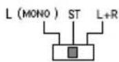
• INPUT MODE SELECTOR
This switch allows the user to specify the input signal to the amplifier.
a) STEREO MODE
b) LEFT MODE (L - MONO)
c) LEFT + RIGHT MODE (L+R)
• END STAGE WITH DISCRETE COMPONENTS (TRANSISTORS)
• HIGH PERFORMANCES, LOW NOISE LEVEL, PASSIVE AND ACTIVE COMPONENTS
• NO CURRENT LIMITATIONS
The current limitation circuits incorporated in traditional amplifiers may cause untimely clipping and a low transient response. The absence of such circuits assures a low T.I.M. effect, an excellent transient response and a perfect sound quality.
• RCA INPUT SENSITIVITY
The new amp has a 500mVsensitivity for ideal coupling with MACROM sources and, however, it is possible to regulate the sensitivity from 100mV to 2V to facilitate coupling with any other source present on the market.
• REMOTE ON AND OFF
On switching the head unit on or off, the amplifier is automatically switched on or off.
- ON/OFF INDICATOR
• THREEFOLD PROTECTION
Your unit is provided with three different protection devices, as befits all high-end products. SOFT START: the amp powers gradually in order to avoid damage to the speakers in case the head unit is switched on with the volume control set to maximum.
OVERHEATING: in case of wrong installation the unit enters the protection mode before being damaged. As soon as the temperature returns to normal values, the unit resumes normal operation.
OUTPUT SHORT CIRCUIT: in case of a short circuit at the speaker outlets the unit enters the protection mode in order to avoid serious damage to the end-stage transistors. Normal operation is resumed on eliminating the short circuit.
• CAPACITIVE/INDUCTIVE POWER SUPPLY FILTER
This filter reduces radio frequency interferences (RFI) and cuts off system noises (i.e. the whine of the alternator).
FEATURES
• MOS-FET Power Supply
The 42.24/42.26 's great power is obtained by means of a special C-Mos-Fet supply unit which offers constant efficiency and requires low electrical input. The results are excellent performances, a linear and wide frequency response with high dynamics.
• GOLD-PLATED RCA INPUT CONNECTIONS
• PROFESSIONAL GOLD-PLATED SCREW-TYPE SUPPLY TERMINALS
• GOLD-PLATED SCREW-TYPE SPEAKER OUTPUT CONNECTIONS
• SPEAKER IMPEDANCE
4 or 2 Ohm for stereo operation, 4 Ohm if mono-bridged
CONTROLS AND INDICATORS
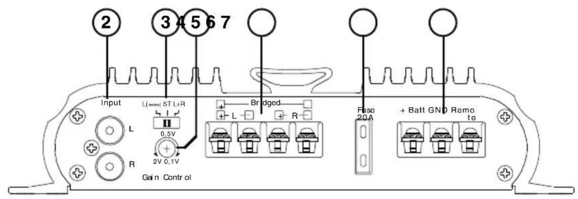
CONTROLS AND INDICATORS (Fig. 2, page 4)
1 ON/OFF indicator
2 Stereo or Mono input signal connector
3 Stereo or Mono input signal selector
4 Input gain control
5 Speaker output connector board
6 Fuse
7 Power supply connector board
INSTALLATION
INSTALLATION (Fig. 1, page 3)
Due to the high output power of the amplifier a great amount of heat is generated when the unit is in use. It is therefore necessary to install the unit in a position with good air circulation otherwise the amp will enter the protection mode. The best place to install the amplifier is in the trunk; avoid covering the amp.
- Place the amplifier at the point of installation chosen and mark the position of the four securing screws provided.
- Drill the screw holes.
- Place the amp in the correct position and fit the four tapping screws in.
NOTE: Connect the ground lead to a screw already fixed to the metallic chassis of the car (indicated by *) in order to ensure a good ground contact.
CONNECTIONS
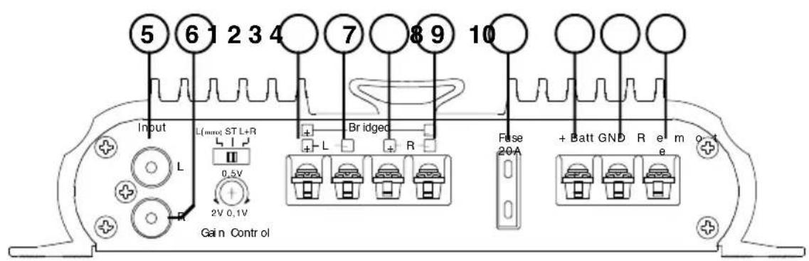
CONNECTIONS (Fig. 3 Pag. 4)
① Positive output terminal for left speaker or positive output terminal if used in MONO
② Negative output terminal for left speaker
③ Positive output terminal for right speaker
④ Negative output terminal for right speaker or negative output terminal if used in MONO
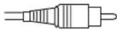
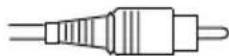
⑤ RCA-type input connector, left channel or mono
⑥ RCA-type input connector, right channel
⑦ 20/25 Ampere fuse
⑧ Feed terminal + 12 V to the battery
Connect this terminal directly to a positive (+) terminal of the battery by means of a lead responding to the amplifiers power requirements.
⑨ Terminal for the connection of the negative ground lead
⑩ Terminal for REMOTE switch-on
- Battery lead. Connect this terminal (+BAT) ⑧ directly to the battery cable of the car, by using an adequately sectioned cable (yellow).
Do not connect this lead to circuits existing within the electric system of the car. In order to avoid damage to the car it is imperative that this lead be fitted with a fuse (not supplied) as near as possible to the car's battery. This connection is to be carried out last. - REMOTE switch-on lead (blue). Connect this lead to the remote switch-on lead or connect the control lead of the power antenna coming from the head unit to the REMOTE terminal ⑩.
NOTE: If this lead is not connected, the amplifier will not be switched on when the head unit is switched on. If your head unit is not fitted with an outlet for a power antenna, a quick-break lever switch (SPST) should be installed between the power source (+12 V) and the remote switch-on lead and connected to the REMOTE ⑩ terminal so as to allow the manual activation of the amplifier. - Ground lead. Secure the ground lead to a clean spot on the car chassis and to the GND terminal ⑨. Make sure that there is electric continuity between this spot and the negative terminal of the battery. Use the shortest possible ground cable and if more than one amp should be used, connect the relative ground to one sole point.
- FUSE. In case of fuse replacement be sure to use fuses of the same amperage.
The use of fuses with the wrong amperage may seriously damage the components of the unit. - SPEAKER OUTLET TERMINALS. Be sure to keep the right polarity and phase in connecting the speakers. This includes the control of the right polarity, positive (+) and negative (-). NOTE: Avoid any contact between stripped wires and the ground lead.
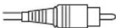
- RCA INPUT CONNECTORS. The line output leads of your head unit should be connected to the RCA input connectors, respectively RCA right ≈ and RCA left ⑤, by means of a RCA extension cable (e.g. 90.05-90.10-90.25-90.50 by MACROM). Be sure to respect the right channel designation: left (white) and right (red).
ADJUSTMENTS AND SWITCHES
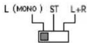
INPUT SELECTOR SWITCH
a) STEREO MODE. Select the "ST" (mid) position when the amplifier is used as a 2-channel stereo system.
Note: Even in this case the connection is possible L + R -.

b) LEFT MODE "L - MONO". Select the "L - Mono" position when the amplifier is used for only one channel of the stereo system or for one bridged channel.
Note: Connect the leads coming from one speaker to the terminals (L+ R-) in order to obtain a BTL-connection. In case stereo output is requested, connect a second 42.24 / 42.26 in the same way to the other speaker.

c) L + R MODE. Select the "L+R" position when the amplifier is used for a subwoofer system using the right and left channels. Thus, the two inputs are blended into one mono output signal divided between 2 channels or, one double power channel if the Sub Woofer is connected to the central channel L + R.

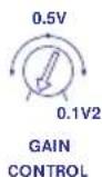
INPUT GAIN ADJUSTMENT CONTROL
In the mid position an input sensitivity of 500 mV is selected corresponding to the preamplified outputs of MACROM products.

If the amplifier is to be connected to a head unit that is not of MACROM make but is fitted with preamplified RCA outputs proceed as follows:
a) Adjust the volume control of your head unit to 3/4 of a turn from the maximum output level.
b) Turn the input control by means of a screwdriver and adjust the input gain from 0.1 V to 2 V to the maximum sound level where no distortion occurs.
TECHNICAL DATA
42.24 STEREO Power Output
Maximum power 60Wx2
Nominal RMS 4 Ohm, 20 Hz to 20 kHz at 0,05% THD ..... 45Wx2
Nominal RMS 2 Ohm, 20 Hz to 20 kHz at 0,05% THD ..... 75Wx2
BRIDGED Power Output
Maximum power, 4 Ohm, 1 kHz 125W
42.26 STEREO Power Output
Maximum power 80Wx2
Nominal RMS 4 Ohm, 20 Hz to 20 kHz at 0,05% THD ..... 65Wx2
Nominal RMS 2 Ohm, 20 Hz to 20 kHz at 0,05% THD ...... 80Wx2
BRIDGED Power Output
Maximum power, 4 Ohm, 1 kHz 156W
Frequency response +0, -1dB 10-50,000 Hz
S/N (signal to noise ratio) INFA-weighted 105 dB
Input sensitivity/Impedance
(for nominal power output)
Control in mid position 500 mV/10k Ohm
Variable control 100-2,000mV/10k Ohm
Speaker impedance 4 or 2 Ohm (stereo)
4 Ohm (bridged, mono)
Power supply (negative ground) 14.0V DC (11-16 V permissible)
Net Weight
42.24....1.6 kg
42.26....1.8 kg
Chassis size
42.24....217(L)x50(H)x150(P) mm
42.26....217(L)x50(H)x190(P) mm
Due to continuing improvement, the features and the design are subject to change without notice.
EINFÜHRUNG
Maximum, 4 Ohm, 1 kHz 200W
42.15 150(L)x50 (H)x217(P) mm
42.17 180(L)x50 (H)x217(P) mm
Nominale RMS 4 Ohms, 1 kHz at 1% THD 45Wx2
Nominale RMS 4 Ohms, 20Hz to 20 kHz at 0.05% THD ..... 35Wx2
Power Output a PONTE
Nominale RMS 4 Ohms, 1 kHz at 1% THD 65Wx2
Nominale RMS 4 Ohms, 20Hz to 20 kHz at 0.05% THD ..... 50Wx2
Power Output a PONTE
42.15 150 (L) x 50 (A) x 217 (P) mm
42.17 180 (L) x 50 (A) x 217 (P) mm
Nominal RMS, 4 Ohms, 1 kHz a 1% THD 45Wx2
Nominal RMS, 4 Ohms, 20 Hz a 20 kHz a 0,05% THD ..... 35Wx2
Nominal RMS, 4 Ohms, 1 kHz a 1% THD 65Wx2
Nominal RMS, 4 Ohms, 20 Hz a 20 kHz a 0,05% THD ..... 50Wx2
42.15 150(L)x50(A)x217(P) mm
42.17 180(L)x50(A)x217(P) mm



- CONTENTS / INHALT / TABLE DE MATIERES / INDICE
- "ENGLISH"
- " DEUTSCH "
- CONNECTIONS / ANSCHLUSSE / CONNEXIONS COLLEGAMENTI / CONEXIONES
- SYSTEM DIAGRAM / SYSTEM-DIAGRAMM / EXEMPLES DE SYSTEME DIAGRAMMA DI SISTEMA / DIAGRAMA DEL SISTEMA
- SYSTEM CHART / SYSTEM-DIAGRAMM / EXEMPLES DE SYSTEME DIAGRAMMA DI SISTEMA / DIAGRAMA DEL SISTEMA
- INTRODUCTION
- PRECAUTIONS
- FEATURES
- • INPUT MODE SELECTOR
- • END STAGE WITH DISCRETE COMPONENTS (TRANSISTORS)
- • HIGH PERFORMANCES, LOW NOISE LEVEL, PASSIVE AND ACTIVE COMPONENTS
- • NO CURRENT LIMITATIONS
- • RCA INPUT SENSITIVITY
- • REMOTE ON AND OFF
- - ON/OFF INDICATOR
- • THREEFOLD PROTECTION
- • CAPACITIVE/INDUCTIVE POWER SUPPLY FILTER
- • MOS-FET Power Supply
- • GOLD-PLATED RCA INPUT CONNECTIONS
- • PROFESSIONAL GOLD-PLATED SCREW-TYPE SUPPLY TERMINALS
- • GOLD-PLATED SCREW-TYPE SPEAKER OUTPUT CONNECTIONS
- • SPEAKER IMPEDANCE
- CONTROLS AND INDICATORS
- CONTROLS AND INDICATORS (Fig. 2, page 4)
- INSTALLATION
- INSTALLATION (Fig. 1, page 3)
- CONNECTIONS
- CONNECTIONS (Fig. 3 Pag. 4)
- ADJUSTMENTS AND SWITCHES
- INPUT SELECTOR SWITCH
- INPUT GAIN ADJUSTMENT CONTROL
- TECHNICAL DATA
- STEREO Power Output
- STEREO Power Output
- EINFÜHRUNG
Brand : Macrom
Model : 42.26
Category : Car radio