
45.40 - Car radio Macrom - Free user manual and instructions
Find the device manual for free 45.40 Macrom in PDF.
| Product type | Five-channel amplifier (2 front channels, 2 rear channels, 1 subwoofer channel) |
| Brand | Macrom |
| Model | 45.40 |
| Dimensions (W x H x D) | 217 x 49 x 370 mm |
| Weight | 3.5 kg |
| Power supply | 14.4 V DC (11 to 16 V possible) |
| RMS power (12.5 V) | Front: 2 x 45 W (4Ω), Rear: 2 x 35 W (4Ω), Sub: 1 x 80 W (4Ω) |
| Dynamic power (14.4 V) | Front: 2 x 65 W (4Ω), 2 x 90 W (2Ω) ; Rear: 2 x 50 W (4Ω), 2 x 70 W (2Ω) ; Sub: 1 x 115 W (4Ω), 1 x 130 W (2Ω) |
| Input sensitivity | 200 to 4000 mV (adjustable) |
| Minimum impedance | 2 Ω |
| Signal-to-noise ratio | >100 dB |
| Distortion rate | 0.08 % |
| Frequency response | 10 – 50,000 Hz (±1 dB) |
| Filters | High-pass (Front/Rear): Flat, 63 Hz, 80 Hz ; Low-pass (Sub): 50 Hz, 80 Hz, 120 Hz ; Slope 12 dB/octave |
| Phase adjustment | Continuous for Sub output (Wave Alignment) |
| Power supply | MOS-FET with dual DC-DC converter |
| Inputs | Gold-plated RCA (4 channels or 2 channels via selector) |
| Speaker outputs | Gold-plated screw terminals |
| Protections | Overheating, overload, short circuit; Check Control LED (white/green/red) |
| Remote turn-on | Yes (REMOTE-ON terminal) |
| Maintenance | Clean with a dry cloth; do not use solvents. Replace fuses with identical models. |
| Safety | Connect the battery last; use appropriately sized cables; never repair yourself. |
Frequently Asked Questions - 45.40 Macrom
User questions about 45.40 Macrom
0 question about this device. Answer the ones you know or ask your own.
Ask a new question about this device
Download the instructions for your Car radio in PDF format for free! Find your manual 45.40 - Macrom and take your electronic device back in hand. On this page are published all the documents necessary for the use of your device. 45.40 by Macrom.
USER MANUAL 45.40 Macrom
Power Speaker Connector
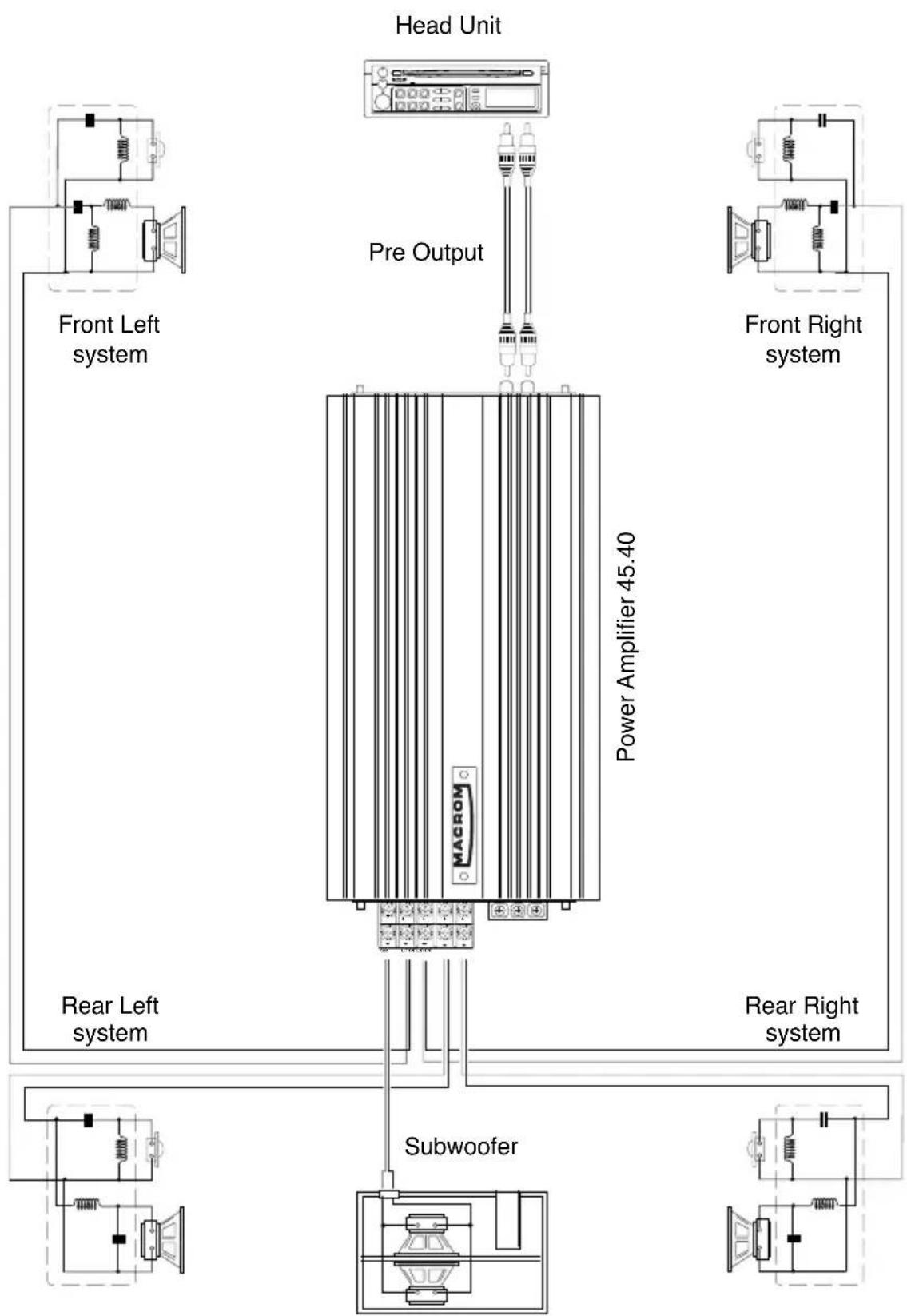
SYSTEM CHART / SYSTEM-DIAGRAMM / EXAMPLES DE SYSTEME / DIAGRAMMA DI SISTEMA / DIAGRAMA DEL SISTEMA
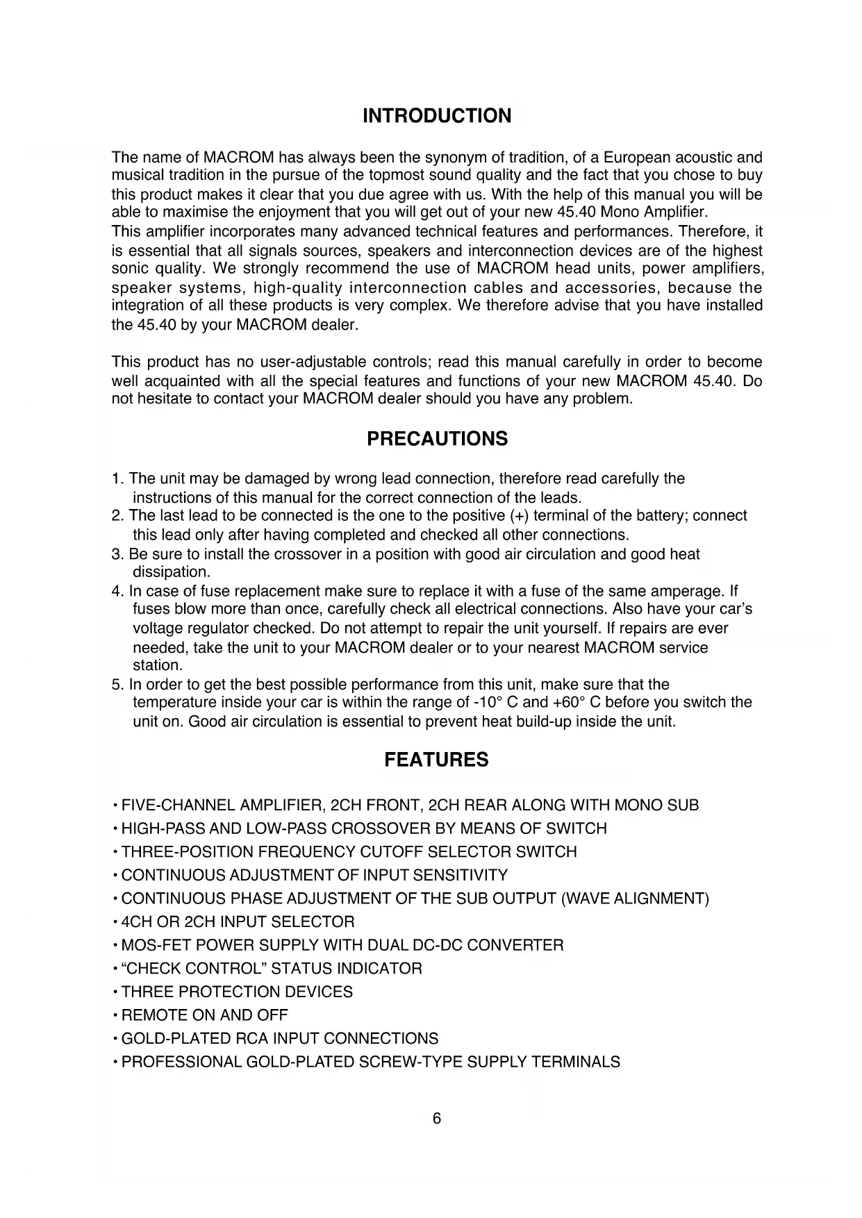
The name of MACROM has always been the synonym of tradition, of a European acoustic and musical tradition in the pursuit of the topmost sound quality and the fact that you chose to buy this product makes it clear that you due agree with us. With the help of this manual you will be able to maximise the enjoyment that you will get out of your new 45.40 Mono Amplifier.
This amplifier incorporates many advanced technical features and performances. Therefore, it is essential that all signals sources, speakers and interconnection devices are of the highest sonic quality. We strongly recommend the use of MACROM head units, power amplifiers, speaker systems, high-quality interconnection cables and accessories, because the integration of all these products is very complex. We therefore advise that you have installed the 45.40 by your MACROM dealer.
This product has no user-adjustable controls; read this manual carefully in order to become well acquainted with all the special features and functions of your new MACROM 45.40. Do not hesitate to contact your MACROM dealer should you have any problem.
PRECAUTIONS
- The unit may be damaged by wrong lead connection, therefore read carefully the instructions of this manual for the correct connection of the leads.
- The last lead to be connected is the one to the positive (+) terminal of the battery; connect this lead only after having completed and checked all other connections.
- Be sure to install the crossover in a position with good air circulation and good heat dissipation.
- In case of fuse replacement make sure to replace it with a fuse of the same amperage. If fuses blow more than once, carefully check all electrical connections. Also have your car's voltage regulator checked. Do not attempt to repair the unit yourself. If repairs are ever needed, take the unit to your MACROM dealer or to your nearest MACROM service station.
- In order to get the best possible performance from this unit, make sure that the temperature inside your car is within the range of -10^ and +60^ before you switch the unit on. Good air circulation is essential to prevent heat build-up inside the unit.
FEATURES
FIVE-CHANNEL AMPLIFIER, 2CH FRONT, 2CH REAR ALONG WITH MONO SUB
HIGH-PASS AND LOW-PASS CROSSOVER BY MEANS OF SWITCH
- THREE-POSITION FREQUENCY CUTOFF SELECTOR SWITCH
CONTINUOUS ADJUSTMENT OF INPUT SENSITIVITY
- CONTINUOUS PHASE ADJUSTMENT OF THE SUB OUTPUT (WAVE ALIGNMENT)
- 4CH OR 2CH INPUT SELECTOR
MOS-FET POWER SUPPLY WITH DUAL DC-DC CONVERTER
- "CHECK CONTROL" STATUS INDICATOR
- THREE PROTECTION DEVICES
- REMOTE ON AND OFF
GOLD-PLATED RCA INPUT CONNECTIONS
PROFESSIONAL GOLD-PLATED SCREW-TYPE SUPPLY TERMINALS
CONTROLS AND INDICATORS
1 - FRONT/SUB INPUT CONNECTORS: Connect the pre-output leads of the head unit to the input connectors of the amplifier. This input will drive the end section of both the FRONT section and the SUB one.
2 · REAR INPUT CONNECTORS: Connect the pre-output leads of the head unit to the input connectors of the amplifier. This input will drive the end section of the REAR section.
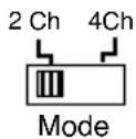
3·4CH/2CH INPUT MODE SELECTOR:It allows to select the amplifier's input configuration as follows:
a) "4ch" - the operation of the five channels depends upon the connection of the four input channels
b) "2ch" - utilize the FRONT/SUB inputs to drive the five channels by means of two inputs only.
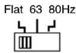
4·FRONT CROSSOVER SELECTOR: II allows to select the FRONT amplifier's operation mode:
a) "FLAT": the FRONT amplifier reproduces the whole audio range on grounds of the signal present at its input;
b) "63 Hz": the High-Pass crossover is activated at 63 Hz to determine the starting value of the high frequencies present at FRONT outputs;
c) "80 Hz": the High-Pass crossover is activated at 80 Hz to determine the starting value of the high frequencies present at FRONT outputs.
5·FRONT INPUT GAIN ADJUSTMENT CONTROL: It allows to adjust input sensitivity to the FRONT section from 200 mV to 4 V.
6 · REAR CROSSOVER SELECTOR: It allows to select the REAR amplifier's operation mode:
a) "FLAT": the REAR amplifier reproduces the whole audio range on grounds of the signal present at its input;
b) "63 Hz": the High-Pass crossover is activated at 63 Hz to determine the starting value of the high frequencies present at REAR outputs;
Flat 63 80Hz
c) "80 Hz": the High-Pass crossover is activated at 80 Hz to determine the starting value of the high frequencies present at REAR outputs.
7 · REAR INPUT GAIN ADJUSTMENT CONTROL: It allows to adjust input sensitivity to the REAR section from 200mV to 4V .
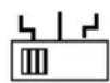
8 · SUB CROSSOVER SELECTOR: It allows to select the crossover frequency of the SUB amplifier:
a) "50 Hz": the Low-Pass crossover is activated at 50 Hz to determine the end point of the low frequencies present at SUB output;
b) "80 Hz": the Low-Pass crossover is activated at 80 Hz to determine the end point of the low frequencies present at SUB output;
c) "120 Hz": the Low-Pass crossover is activated at 120 Hz to determine the end point of the low frequencies present at SUB output.
50 80 120Hz

9·SUB INPUT GAIN ADJUSTMENT CONTROL:
It allows to adjust input sensitivity to the Sub section from 200mV to 4V .
CONTROLS AND INDICATORS
10 · SUB OUTPUT PHASE ADJUSTMENT: It allows the continuous phase adjustment in the
region comprised between Min and Max of the SUB output compared to the FRONT and REAR outputs. The easiest way to determine the "Wave Alignment" is to use a third-of-octave sound analyzer. Utilize a CD with a pink noise track and position the microphone exactly at ear level in the driver's seat. Adjust the Wave Alignment as follows:

Min. Max.
Turn the potentiometer of the "Wave alignment" until the crossover point between the SUB section and the other sections reaches the maximum value. The audio analyzer will display the maximum increase.
If the same adjustment is to be made without the relevant instrument, one must rely on his own ears. Utilize again a CD with a pink noise track or a well known sound track.
Turn the Wave Alignment potentiometer until low frequencies increase.
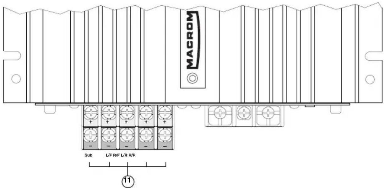
11 · SPEAKER CONNECTOR: Outputs for speaker connection. The amplifier allows to connect speakers with minimum 2-ohm impedance per channel.
NOTE: No mono or mixed-mono bridge configuration is possible.
Be sure to keep the right polarity and phase in connecting the speakers.
Avoid any contact between poorly insulated wires and the car's ground or metal pieces and between the wires themselves.
12 · BAT + CONNECTOR: to be connected directly to battery + by means of a fuse located close to the battery itself. Utilize a cable having an adequate section. Do not connect this cable to the car's electrical system wiring (eg.: dome-light circuit, car radio etc.)
13 · GND CONNECTOR: connect the ground terminal to a clean base metal part of the vehicle chassis (if possible, to an existing screw). Utilize a cable having an adequate section.
14 - REMOTE-ON CONNECTOR: to be connected either to the remote switch-on output lead or to the output lead of the power antenna coming from the head unit. As a result, the 45.40 will be switched on and off simultaneously with the head unit.
15·CHECK CONTROL LED: this led shows the amplifier's status of operation :
WHITE: the unit is off
GREEN: the unit is working OK
RED: the unit has entered the protection mode
The 45.40 is equipped with three different protection devices:
Overheating: in case of wrong installation the unit enters the protection mode before being damaged. As soon as the temperature returns to normal values, the unit resumes normal operation.
Overload: if several speakers are connected to the amplifier and the total impedance decreases below the allowable threshold (0.5 - 1 ohm), the amplifier enters automatically the protection mode to avoid any damage. To restore normal operation the head unit has to be switched off and then on again.
Output short circuit: in case of a short circuit at the speakers outputs, the unit enters the protection mode to avoid serious damage to the end stage transistors. Normal operation is restored by eliminating the short circuit and by switching on the head unit again.
TECHNICAL DATA
RMS Power measured at 12.5 Volts DC:
Total maximum power 450 Watts
Front @ 1 kHz < 0.08 % THD into a 4 ohms load 2 x 45 Watts
Rear @ 1 kHz < 0.08 % THD into a 4 ohms load 2 x 35 Watts
Sub @ 50 Hz < 0.1 % THD into a 4 ohms load 1 x 80 Watts
Dynamic Power measured at 14.4 Volts DC:
Front @ 1 kHz < 0.1 % THD into a 4 ohms load 2 x 65 Watts
Rear @ 1 kHz < 0.1 % THD into a 4 ohms load 2 x 50 Watts
Sub @ 50 Hz < 0.1 % THD into a 4 ohms load 1 x 115 Watts
Front @ 1 kHz into a 2 ohms load 2 x 90 Watts
Rear @ 1 kHz into a 2 ohms load
2 x 70 Watts
Sub @ 50 Hz into a 2 ohms load 1 x 130 Watts
Crossover frequencies
High-Pass, Front/Rear Flat, 63 or 80Hz
Low-Pass, Sub
50, 80 or 120Hz
Crossover slope
12 dB/Octave
Frequency response ± 1 dB
10-50,000 Hz
Total harmonic distortion
0.08%
Signal-to-noise ratio (IHFA-weighted)
100dB
Input sensitivity/Impedance at 12.5Volt DC
200-4000 mV/20 kohms
Speakers' impedance
2 ohms min
Power supply
14.4 V DC (11-16 V allowed)
Weight
3.5Kg
Size
217(I) x 49(h) x 370(d) mm
Due to continuing improvement, the features and the design are subject to change without notice.
THEORY OF OPERATION
CONTINUOUS PHASE ADJUSTMENT
The effects of phase shift. The unavoidable consequence of the configuration is the phase shift, which we will not comment at length as it goes far beyond the boundaries of this discussion. It is enough to say that any crossover network affecting the signal amplitude also affects the phase.
What is the phase? The phase is the time reaction between two signals. You probably encountered this basic problem in connecting two speakers to a stereo system. If the two speakers are "out of phase", the bass frequencies are output only partially giving as a result a "LEAN" sound. On inverting the wires of one speaker the problem can be solved because the phase of the signal that goes to that speaker is inverted. This is an example for a phase shift of 180^ between two speakers of the same section (low pass); with crossovers it is possible to have phase shifts also between different sections; they can reach from 0^ and change gradually to 360^ .
Phase shift caused by crossover filters affects the following characteristics:
1) the ability of the crossover/speaker system to reproduce the wave form
2) the flatness of the combined acoustic output of two or more speakers (low and high)
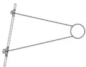
3) the radiation angle of the speaker. Various crossovers produce different outputs with different radiation angles
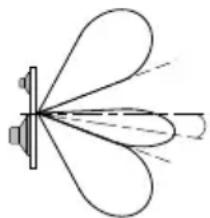
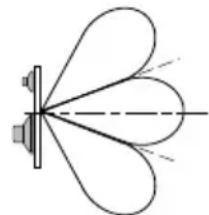
where the combined output of several speakers reaches a peak. The figure explains the concept of radiation. The change of radiation angle is caused by the phase shift that is sensitive to the frequencies at the crossover point. The fundamental concepts for the choice of a crossover curve and of the cutoff characteristics are based upon the following:
a) considerations about the speaker system
b) the effect of the phase shift of the crossover and the positioning of the speakers with regard to the frequency response of the global system.
Phase alignment the crossover and the speaker: the best way to allow a speaker system to accurately reproduce the pulses of a wave pattern is the positioning of the speakers in such a way that the wave front coming from different sources reaches the ears of the listener in exactly the same time fraction; the improvement of this characteristic is called phase
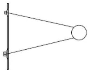
alignment or time alignment. This concept is better explained by the figure. Sound travels at a speed of approx. 1100 ft./sec. through air; therefore, a distance of 12 inches stands for a delay of one millisecond at 1000Hz . If two speakers are not well aligned the waves forming the wave front reach the ear with a delay one with respect to the other. This problem in phase alignment is particularly acute in the near regions of the cutoff frequencies because all the speakers contribute to the overall output of the system; any delay between the sound sources (woofer, tweeter) gives as a result an unbalanced frequency response in the region around the cutoff frequency. The best way to minimize this problem is to physically correct the vertical alignment of the different speakers until the perfect alignment of their single acoustic center points is obtained. Due to this adjustment the distance between the speaker and the listener is the same for all the speakers within the system thus arranging them on the same acoustic level.
EINFUHRUNG
Front @ 1 kHz a 2Ω 2 x 90W
Rear @ 1 kHz a 2Ω 2 x 70W
Subwoofer @ 50 Hz a 2Ω 1 x 130W
Frequenze del Crossover
Passa alto, Front e Rear Flat - 63 - 80 Hz
Passa Basso, Subwoofer
50-80-120Hz
Pendenza d'incrocio
12 dB/Octave
CONTROSES E INDICADOS
Frontales @ 1 kHz a 2Ω 2 x 90W
Traseros @ 1 kHz a 2Ω 2 x 70W
Subwoofer @ 50 Hz a 2Ω 1 x 130W


- SYSTEM CHART / SYSTEM-DIAGRAMM / EXAMPLES DE SYSTEME / DIAGRAMMA DI SISTEMA / DIAGRAMA DEL SISTEMA
- PRECAUTIONS
- FEATURES
- CONTROLS AND INDICATORS
- TECHNICAL DATA
- RMS Power measured at 12.5 Volts DC:
- Dynamic Power measured at 14.4 Volts DC:
- Crossover frequencies
- THEORY OF OPERATION
- CONTINUOUS PHASE ADJUSTMENT
- EINFUHRUNG
- Frequenze del Crossover
- CONTROSES E INDICADOS
Brand : Macrom
Model : 45.40
Category : Car radio