
ST 55 800 TEXT - Television GRUNDIG - Free user manual and instructions
Find the device manual for free ST 55 800 TEXT GRUNDIG in PDF.
| Product type | Color CRT television with teletext |
| Brand | Grundig |
| Model | ST 55 800 TEXT |
| Power supply | 220-240 V, 50/60 Hz (range 165-265 V) |
| Power consumption | Approx. 70 W (standby: 9 W) |
| Reception ranges | Channels C01 to C99, special channels S01 to S41 |
| Audio output power | 2 x 8 W music power (2 x 4 W sine) |
| Main functions | Automatic ATS search, teletext, audio menu (stereo/mono, stereo width, treble, bass, balance), built-in decoder, SCART input, S-VHS, headphone, sleep timer, standby switching |
| Connectivity | 1 SCART socket (EURO-AV), video/audio input for camcorder (RCA sockets), 3.5 mm headphone jack, antenna socket |
| Maintenance and cleaning | Regular dusting of ventilation slots by a specialist to prevent heat buildup |
| Safety | Disconnect antenna and mains during storms; do not block ventilation slots; avoid moisture; do not insert objects into slots |
| Spare parts and repairability | Replacement mains cable: reference GWN 9.22 / product number 8290.991-316; any modification to the high voltage or the picture tube may increase X-ray radiation and render the device non-compliant |
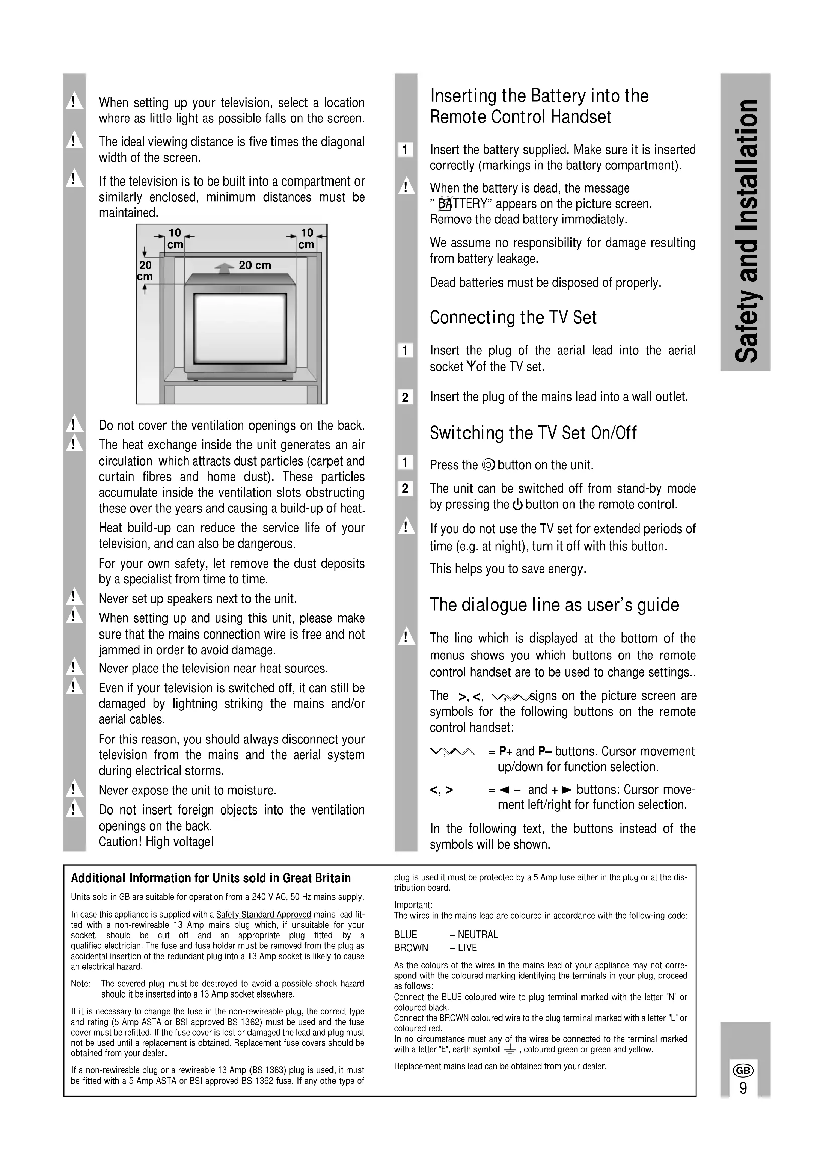
| General information | Ideal viewing distance: 5 times the screen diagonal; minimum clearance around the device: 10 cm on the sides, 20 cm at the top and rear |
Frequently Asked Questions - ST 55 800 TEXT GRUNDIG
User questions about ST 55 800 TEXT GRUNDIG
0 question about this device. Answer the ones you know or ask your own.
Ask a new question about this device
Download the instructions for your Television in PDF format for free! Find your manual ST 55 800 TEXT - GRUNDIG and take your electronic device back in hand. On this page are published all the documents necessary for the use of your device. ST 55 800 TEXT by GRUNDIG.
USER MANUAL ST 55 800 TEXT GRUNDIG
natural_image
Architectural line drawing of a room with monitor, printer, and lamp (no text or symbols)text_image
EURO-AV WALO WALO WALO WALO WALO WALO WALO WALO WALO WALO WALO WALO WALO WALO WALO WALO WALO WALO WALO WALO WALO WALO WALO WALO WALO WALOUAnschließen
natural_image
Close-up of a CD or audio device showing an audio jack connected to a pair of headphones (no text or symbols visible)Anschließen
natural_image
Diagram of a computer monitor showing an Ethernet cable and an attached USB drive (no text or symbols present)3 = Audio Ausgang links
4 = Audio Masse
5 = Blau Masse
6 = Audio Eingang links
When setting up your television, select a location where as little light as possible falls on the screen.
The ideal viewing distance is five times the diagonal width of the screen.
If the television is to be built into a compartment or similarly enclosed, minimum distances must be maintained.
text_image
10 cm 20 cm 20 cm 10 cmDo not cover the ventilation openings on the back.
The heat exchange inside the unit generates an air circulation which attracts dust particles (carpet and curtain fibres and home dust). These particles accumulate inside the ventilation slots obstructing these over the years and causing a build-up of heat.
Heat build-up can reduce the service life of your television, and can also be dangerous.
For your own safety, let remove the dust deposits by a specialist from time to time.
Never set up speakers next to the unit.
When setting up and using this unit, please make sure that the mains connection wire is free and not jammed in order to avoid damage.
Never place the television near heat sources.
Even if your television is switched off, it can still be damaged by lightning striking the mains and/or aerial cables.
For this reason, you should always disconnect your television from the mains and the aerial system during electrical storms.
Never expose the unit to moisture.
Do not insert foreign objects into the ventilation openings on the back.
Caution! High voltage!
Inserting the Battery into the Remote Control Handset
1 Insert the battery supplied. Make sure it is inserted correctly (markings in the battery compartment).
When the battery is dead, the message "BATTERY" appears on the picture screen. Remove the dead battery immediately.
We assume no responsibility for damage resulting from battery leakage.
Dead batteries must be disposed of properly.
Connecting the TV Set
1 Insert the plug of the aerial lead into the aerial socket Y of the TV set.
2 Insert the plug of the mains lead into a wall outlet.
Switching the TV Set On/Off
1 Press the Ⓞ button on the unit.
2 The unit can be switched off from stand-by mode by pressing the ⏻ button on the remote control.
! If you do not use the TV set for extended periods of time (e.g. at night), turn it off with this button.
This helps you to save energy.
The dialogue line as user's guide
! The line which is displayed at the bottom of the menus shows you which buttons on the remote control handset are to be used to change settings..
The >, <, ∨, ∧ signs on the picture screen are symbols for the following buttons on the remote control handset:
$$ \begin{array}{r l} \text { V }, & = \mathbf {P} + \text { and } \mathbf {P} - \text { buttons. Cursor movement } \ & \text { up / down for function selection. } \end{array} $$
$$ < , > \quad = \blacktriangleleft - \text { and } + \blacktriangleright \text { buttons: Cursor movement left / right for function selection. } $$
In the following text, the buttons instead of the symbols will be shown.
Additional Information for Units sold in Great Britain
Units sold in GB are suitable for operation from a 240 V AC, 50 Hz mains supply.
In case this appliance is supplied with a Safety Standard Approved mains lead fitted with a non-rewireable 13 Amp mains plug which, if unsuitable for your socket, should be cut off and an appropriate plug fitted by a qualified electrician. The fuse and fuse holder must be removed from the plug as accidental insertion of the redundant plug into a 13 Amp socket is likely to cause an electrical hazard.
Note: The severed plug must be destroyed to avoid a possible shock hazard should it be inserted into a 13 Amp socket elsewhere.
If it is necessary to change the fuse in the non-rewireable plug, the correct type and rating (5 Amp ASTA or BSI approved BS 1362) must be used and the fuse cover must be refitted. If the fuse cover is lost or damaged the lead and plug must not be used until a replacement is obtained. Replacement fuse covers should be obtained from your dealer.
If a non-rewireable plug or a rewireable 13 Amp (BS 1363) plug is used, it must be fitted with a 5 Amp ASTA or BSI approved BS 1362 fuse. If any other type of
plug is used it must be protected by a 5 Amp fuse either in the plug or at the distribution board.
Important:
The wires in the mains lead are coloured in accordance with the following code:
$$ \begin{array}{l l} \text {BLUE} & - \text {NEUTRAL} \ \text {BROWN} & - \text {LIVE} \end{array} $$
As the colours of the wires in the mains lead of your appliance may not correspond with the coloured marking identifying the terminals in your plug, proceed as follows:
Connect the BLUE coloured wire to plug terminal marked with the letter "N" or coloured black.
Connect the BROWN coloured wire to the plug terminal marked with a letter "L" or coloured red.
In no circumstance must any of the wires be connected to the terminal marked with a letter 'E', earth symbol 12 , coloured green or green and yellow.
Replacement mains lead can be obtained from your dealer.
1st Possibility
The Automatic Tuning System ATS
This automatic tuning system scans the entire reception range and automatically stores the channels found in memory.
How to proceed:
1 Switch the TV set on from standby with one of the buttons 1...9.
2 Press for approximately 4 seconds on the P/C button to display the ATS menu.
3 Press the OK-button to start the search function.
The search can last longer than one minute. When it has stopped, setting of the TV set is completed.
If you do not like the order in which the programmes are stored on the programme positions, you can change this according to your preferences.
The search can be aborted using the i button.
Changing the Programme Order
Example: you wish to move the programme stored on position 2 to position 5.
1 Select programme position 2.
2 Press the P/C button. The programme menu is displayed.
3 Under "PR", enter the new programme position number 05 as two digits with the buttons 1...9.
4 Press the OK-button to terminate the adjustment.
5 Press the i button to return to TV mode.
2nd Possibility
Direct Channel Entry
For this, you need to know the channel numbers of the TV prgrammes.

If you have already assigned the programmes to the programme positons with the help of the ATS function, this procedure is not required.
How to proceed:

Press the P/C-button to display the programme menu.

Attention - this is not possible in the AV position.
| PR | CH | DEC | FT | |
| 22 | S06 | ON | 00 | |
| 0-9 | <> | OK | i | |
Dialogue line
Press the ◀ - or + ▶ button to select the desired item.

Under "PR" press P+/P- to select the desired programme position.
" "CH" enter channel number, (for special channel, press P+ or P- to select "S" instead of "C").
Press the +▶button. Use the numbered buttons to enter the required channel number.
Hold down P+ or P- to start the channel search. This stops at each programme being received.
" "DEC" If an encrypted programme is allocated to the programme position and a corresponding decoder connected, select "ON".
" "FT" If fine tuning should be necessary after programme allocating, then press P+ or P- until the best picture and sound quality is obtained.

Press OK to store the modified settings.
The programme data of the next programme position is displayed.

Press it to return to the television picture.

If the channel number 00 is entered with P+ or P-on one programme position, all following programme positions can no longer be selected.
text_image
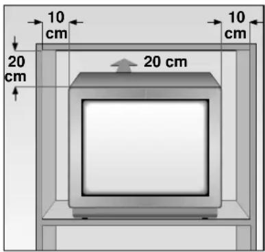
1...9 Select programme position (- P + on set) and 0/AV switch the TV set on from standby or select AV position. P+ / P- Select programme positions step by step: P+ : (1, 2, 3 ...), P- : (...3, 2, 1) or P+ : switch on from standby with last selected programme position. Move cursor up or down. OK Modify and activate various functions. Press OK-button twice: optimum setting. ← -, + ▶ Set volume or move cursor to the left and to the right. Teletext: current page number + 10 pages. Teletext: current page number - 1 Time on/off. Teletext: current page number + 1 Colour contrast. VIDEO Video recorder remote control (press and hold down VIDEO button). AUX Teletext: call up dialogue line. GRUNDIG TP 712 1 ← 2 → 3 4 ↓ 5 ↑ 6 7 ← 8 → 9 0 AV Switch to standby and switch on with last selected program- me position. Sound on/off (mute). i Display/suppress programme number (status page). Set b/w contrast: press i, OK, ← - or + ▶. Set Sleep Timer (switch-off time 01...99 min: press i, OK, i, and numeric buttons 1...9. Automatic frequency control on/off: press i, OK, i, i, ← - or + ▶. Call up Audio menu: i, ▶ TFT Teletext ↔ TV mode Teletext: next hundreds page. +/− Brightness. SAT Satellite receiver remote control (press and hold down SAT button). P/C Call up programme data. Keep pressed for 4 seconds: call up ATS.Every changed value is stored after 8 seconds automatically or when switching to standby.
This television was tested with maximum contrast. It is advisable to turn down the contrast to offer you the best picture quality depending on lighting conditions or on the location where your TV is set up.
If you wish to have the programme position number permanently displayed, press the i button.
To suppress the display, press the i button once again.
Remote Control of a Video Recorder
The remote control handset of your television enables also remote control of Grundig video recorders. Your specialized dealer can tell you which video recorders are suited for this.
Press and hold down the VIDEO button.
This switches the remote control handset into the video recorder mode.
Then press the desired function button.
The following table shows you which buttons are to be used for the different recorder functions.
◀ (Numeric button 1) = Reverse picture search
▶ (Numeric button 2) = Forward picture search
● (- ⊕ button) = Start recording
( ⊙ + button) = Stop
◀ (Numeric button 7) = Fast rewind
▶ (Numeric button 8) = Fast forward wind
II (− ⚙ button) = Pause
▶ ( ⚙ + button) = Start playback
▼ (Numeric button 4) = Programme position -
▲ (Numeric button 5) = Programme position +
The Audio Menu
Calling Up the Audio Menu
1 Press the i and then the ▶ button to display the Audio menu.

text_image
Stereo, mono, two-channel- Stereo expansion - Treble - Bass - Balance - Dialogue line - STEREO MONO ^V < > iAfter any adjustment, the Audio menu can be exited by pressing the i-button.
Stereo, Mono and Two-channel Sound Broadcasts
If your television receives two-channel sound transmissions, for example, when a film is broadcast in the original sound track on sound channel 2 (DUAL B) and the synchronized version is broadcast on sound channel 1 (DUAL A), you can select the desired channel.
1 Press P+ or P- to select the first menu line.
2 Press ←-, +▶ to select the desired sound channel.
If a stereo broadcast is received, the set switches automatically to stereo sound.
! If the stereo sound is poor (weak signal), press ◀-, +▶ to switch to mono.
The mono setting can be stored separately for every programme position by pressing the OK-button.
Indication of the sound mode
Each time the station changes the sound transmission mode (e.g. from mono to stereo), the mode is displayed for approx. 4 seconds.
This indication takes also place when changing the programme, however only if the mode differs from the mono mode.
Stereo Expansion
This function improves the acoustic pattern during stereo broadcasts and improves the sound of mono broadcasts.
1 Use the P+ or P- button to select the corresponding menu line.
2 Adjust with the ◀ - or + ▶ button (the set stereo expansion is retained even when changing the programme position).
Treble, Bass, Balance
The settings of these functions can be corrected as required.
1 Use the P+ or P- button to select the corresponding menu line.
2 Adjust with the P+ or P- button.
Teletext
Call up Teletext: press the TXT button.
Select pages directly with the 1...9 buttons.
(Available pages: 100-899)
Calling up contents page
Press iibutton.
Call up dialogue line: press the AUX button.

text_image
↑ X /00 ? STOP □ □ □ 1 □ 2 5431 = Enlarge character height
2 = Bypass waiting times (actual mode).
3 = Directly call up subpage
4 = Reveal answer
5 = Stop page
Select the functions with the ◀ - or +▶ button and call them up with the OK-button.
The functions 1, 3, 4, and 5 can also be selected without calling up the dialogue line:
1 Enlarge character height: press the + Ⓐbutton.
3 Directly call up subpage: press the - Ⓐbutton.
4 Reveal answer: press the +▶button.
5 Stop page: press the ← button.
Selecting Pages by Means of the Cursor (Page Catching)
i.e. without entering the page numbers. Move the cursor to the desired Teletext page in an overview page (pages containing three-digit page numbers). Using this function, you need not type in the three-digit page numbers.
1 Press the P+ or P- button.
"Page Catching" is displayed on the top screen border.
A light spot (cursor) is flashing on the first or last page number of the overview page.
2 Use the P+ or P- button to move the cursor to the desired page number.
3 Press the OK-button.
The page appears on the picture screen.
Floftext
With Floftext the coloured buttons provide access to the subjects indicated in the dialogue line.
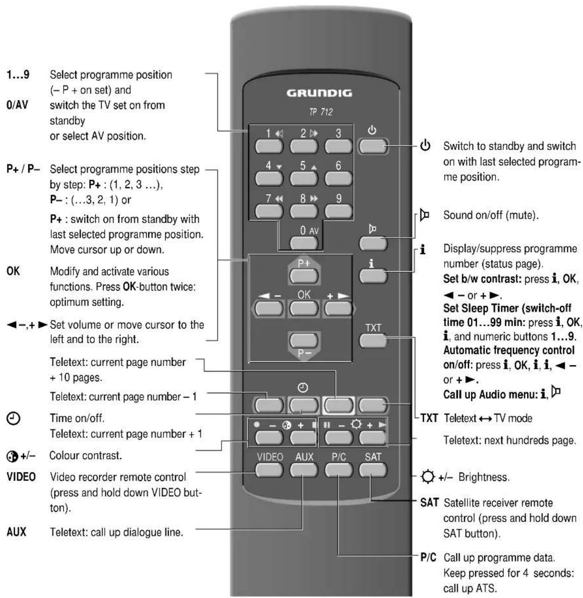
Connecting a Video Recorder or Satellite Receiver
text_image
EURO-AV V032 96619415443 96619415442 V032 96619415441 V032 9661941543 V032 9661941542 V032 9661941541Connection
Connect the video recorder or satellite receiver with an AV lead to the AV socket.
Operating the Video Recorder
1 Press the 0av button.
Until AV1 is indicated.
Start playback on the video recorder.
The video playback is visible on the TV set.
You can also connect an S-VHS video recorder
For this, the AV socket must be switched to S-VIDEO.
1 Press the P/C button.
2 Use the ◀ - or +▶ button to select S-VIDEO.
3 Press the i button to exit the menu.
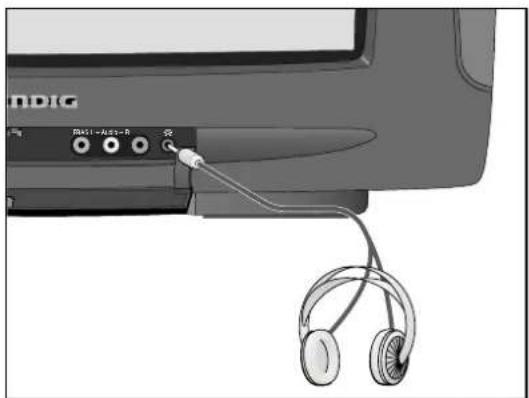
Connecting a Headphone
natural_image
Close-up of a CD-ROM connector with earbuds and cable, no visible text or symbolsConnection
Connect the headphone (3.5 mm ♦ jack) with the Ⓞ socket (the speakers of the TV set ar switched off).
Adjusting the Headphone Volume
1 Adjust with the ◀ -, +▶ buttons.
Connecting a Descrambler (Decoder) or an External Unit (Video Recorder)

natural_image
Diagram of a computer monitor showing an Ethernet cable and an attached USB drive (no text or symbols present)Some providers which offer their programmes via the cable TV system "scramble" the picture and sound signals so that you need a pay-TV decoder (descrambler) if you wish to receive these programmes in a normal way.
How to proceed:
Connect the decoder/video recorder to the EURO-AV socket.
Decoder:
Select the programme position on which the encrypted programme is received.
Video recorder:
Select the programme position on which you wish to see the video playback.
1 Press the P/C-button.
2 Press the ◀ - or + ▶ button to select DEC.
3 Press the P+ or P- button to select ON.
A programme position prepared for decoder operation can be recognized at a fullstop appearing after the P when changing the programme position.
4 Press OK to store the setting.
5 Press i to exit the menu.
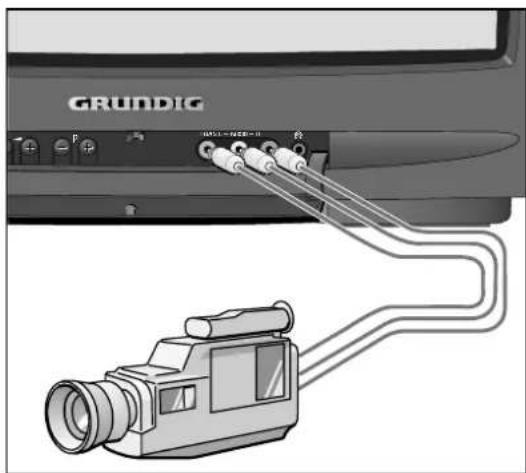
Connecting a Camcorder (VHS, Video 8)
text_image
GRUNDIGConnection
Connecting the video signal
Connect the VIDEO IN socket with the corresponding video socket on the camcorder.
Connecting the audio signal
Connect the L AUDIO IN R sockets with the audio sockets on the camcorder. For mono playback, connect the L AUDIO IN socket with the corresponding audio socket on the camcorder.
Operating the Camcorder
Use the 0 AV button to select AV 2.
Start playback on the camcorder.
The video playback is visible on the TV set.
(It is not possible to copy to the Euro-AV socket!)
Mains voltage:
220 - 240V, 50/60Hz
(power supply control range 165 ... 265V)
This unit may only be operated with the power supply cable set which has been supplied. It prevents interference from the mains, and is considered an obligatory component of this unit.
For a replacement, contact the nearest customer service center and order only the power supply cable set with the following designation: GWN 9.22/article number 8290.991-316.
Power consumption:
approx. 70 W
Standby: 9 W
Channel coverage:
C01 ... C99
Special channels S01 ... S41
Sound output:
2 x 8 W music power (2 x 4 W sine power)
This unit conforms to VDE safety regulations and directives of the Deutsche Bundespost (German Federal Post Office; see certification mark on the type sticker on the rear of the unit), as well as all relevant ordinances governing X-ray emissions. The picture tube, which emits X-rays, is sufficiently shielded and therefore represents no danger. Accelerating voltage is max. 29kV with a mean beam current of 1.0mA.
Unauthorized tampering with the unit, in particular making adjustments to the high voltage system, or installing a different picture tube, can considerably increase X-ray emissions. Units so altered no longer conform to applicable safety regulations and may not be operated.
Subject to alterations. E. and O.E.
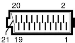
Pin Assignment of EURO-AV Socket
If you want to connect other devices to your television (for example, a computer or amplifier), your dealer can provide you with a normed standard connection by means of the following table:
Pin Signal
1 = Audio output right
2 = Audio input right
3 = Audio output left
4 = Audio, earth
5 = Blue, earth
6 = Audio input left
7 = RGB blue input
8 = Switching voltage
9 = Green, earth
10 = -
11 = RGB green input
12 = -
13 = Red, earth
14 = Earth
15 = RGB red input (chroma for SVideo)
16 = RGB switching voltage
17 = Video, earth
18 = RGB switching voltage, earth
19 = Video output
20 = Video input
21 = Shielding/earth
natural_image
Illustration of a CD or audio device with headphones connected to a key (no text or symbols visible)Collegamento
natural_image
Diagram of a computer monitor showing an Ethernet cable and USB port, with no visible text or symbols.natural_image
Close-up of a CD-ROM connector with earbuds and cable, no visible text or symbolsAansluiten
natural_image
Diagram of a computer monitor showing an Ethernet cable and USB port, with no visible text or symbols.Attention: haute tension!
natural_image
Close-up of a CD or audio device with attached headphones and an external connector (no visible text or symbols)Raccordement
natural_image
Diagram of a computer monitor showing an output cable connected to a CD-ROM drive (no text or symbols present)Raccorder le signal audio
8 = tension de commutation
9 = masse, vert
10 = -
11 = entrée, RVB, vert
12 = -
13 = masse, rouge
14 = masse