F88WG - Computer and peripheral cables Hoffman - Free user manual and instructions
Find the device manual for free F88WG Hoffman in PDF.
| Product Type | High-sealing cable tray |
| Brand | Hoffman |
| Model | F88WG |
| Material | Treated steel with gray polyester powder finish |
| Color | Gray |
| Available dimensions | 2.5 × 2.5 in, 4 × 4 in, 6 × 6 in, 8 × 8 in |
| Weight | Approximately 2 kg/m depending on size |
| Power supply | Not applicable (passive) |
| Main functions | Cable support and management, grounding, telescopic and swivel fittings |
| Usage | Indoor/outdoor, for electrical and data cables |
| Mounting | By brackets, screws and nuts |
| Finish | Gray polyester powder paint |
| Maintenance and cleaning | Clean with a damp cloth, avoid harsh solvents |
| Safety | Ensure grounding continuity, respect maximum loads |
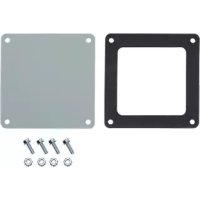
| Spare parts and repairability | Telescopic fittings, swivel fittings, brackets, connectors; replaceable sections |
Frequently Asked Questions - F88WG Hoffman
User questions about F88WG Hoffman
0 question about this device. Answer the ones you know or ask your own.
Ask a new question about this device
Download the instructions for your Computer and peripheral cables in PDF format for free! Find your manual F88WG - Hoffman and take your electronic device back in hand. On this page are published all the documents necessary for the use of your device. F88WG by Hoffman.
USER MANUAL F88WG Hoffman
INDEX INDEX INCRÉMENT INDICE
CONTENT PAGES
INHALT SEITEN
CONTENUE PAGES
CONTENIDO PAGINA
English Instructions 3-5
Installation Instructions
Feed-Through Wireway
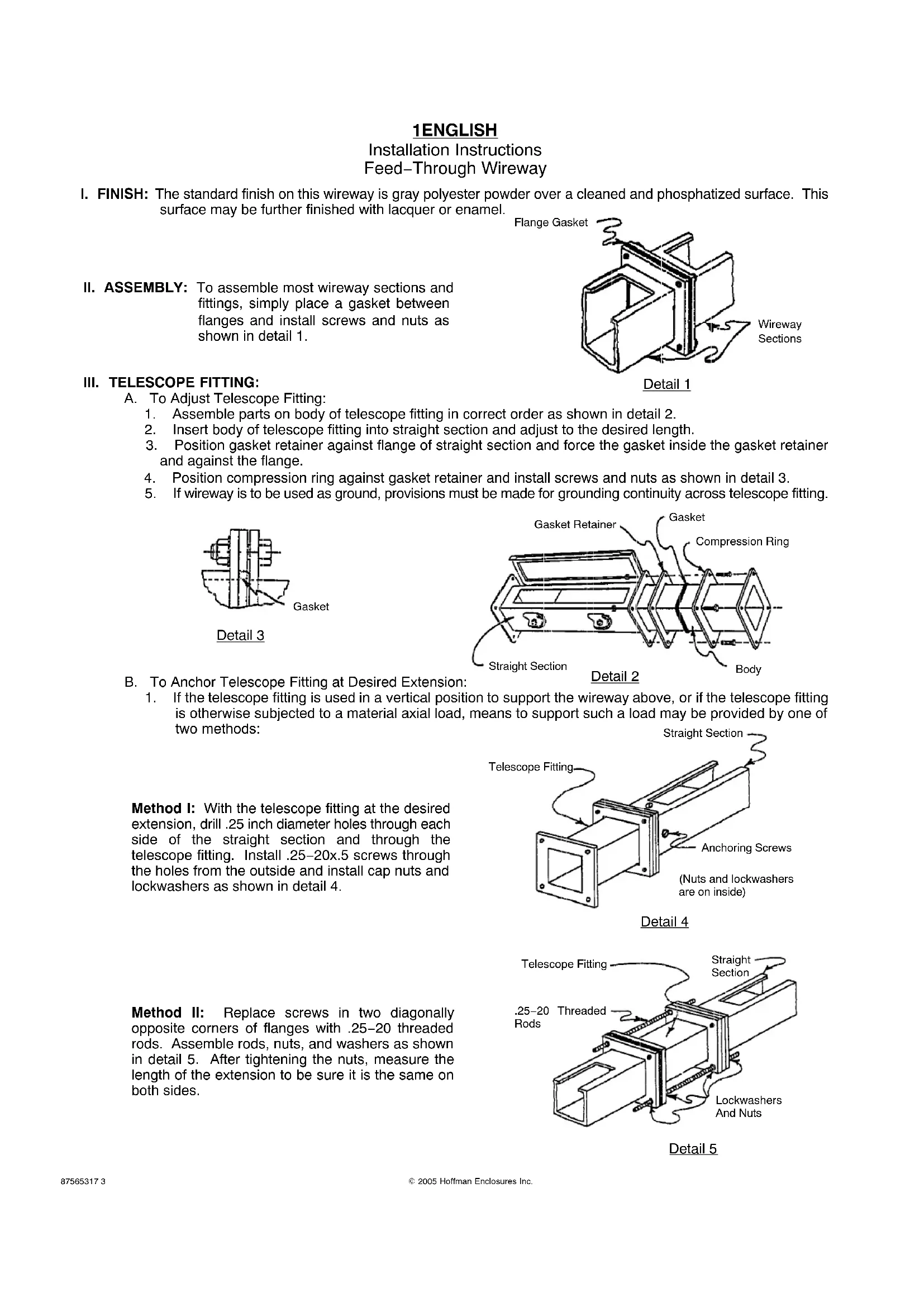
I. FINISH: The standard finish on this wireway is gray polyester powder over a cleaned and phosphatized surface. This surface may be further finished with lacquer or enamel.
Flange Gasket
II. ASSEMBLY: To assemble most wireway sections and fittings, simply place a gasket between flanges and install screws and nuts as shown in detail 1.
Detail 1
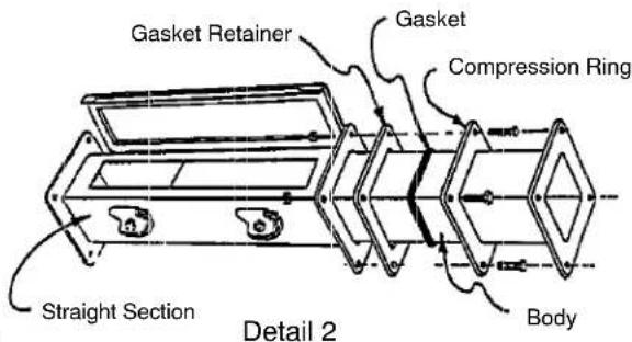
III. TELESCOPE FITTING:
A. To Adjust Telescope Fitting:
- Assemble parts on body of telescope fitting in correct order as shown in detail 2.
- Insert body of telescope fitting into straight section and adjust to the desired length.
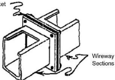
- Position gasket retainer against flange of straight section and force the gasket inside the gasket retainer and against the flange.
- Position compression ring against gasket retainer and install screws and nuts as shown in detail 3.
- If wireway is to be used as ground, provisions must be made for grounding continuity across telescope fitting.
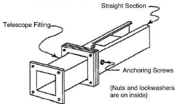
B. To Anchor Telescope Fitting at Desired Extension:
- If the telescope fitting is used in a vertical position to support the wireway above, or if the telescope fitting is otherwise subjected to a material axial load, means to support such a load may be provided by one of two methods: Straight Section
Method I: With the telescope fitting at the desired extension, drill .25 inch diameter holes through each side of the straight section and through the telescope fitting. Install .25-20x.5 screws through the holes from the outside and install cap nuts and lockwashers as shown in detail 4.
Detail 4
Method II: Replace screws in two diagonally opposite corners of flanges with .25-20 threaded rods. Assemble rods, nuts, and washers as shown in detail 5. After tightening the nuts, measure the length of the extension to be sure it is the same on both sides.
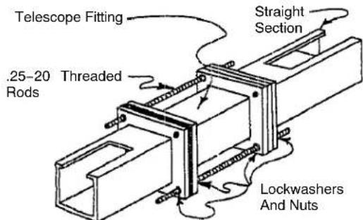
Detail 5
2ENGLISH
Installation Instructions
Feed-Through Wireway
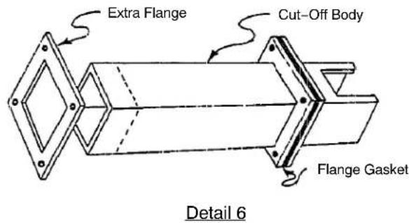
IV. CUT-OFF FITTING: Cut off the body to the desired length. (remember to allow for the flange and gaskets) Be sure the body is cut off squarely. Weld the extra flange to the body. Grind off all burrs and sharp edges. Touch-up paint can be used to duplicate the original finish.
V. SWIVEL NIPPLES:
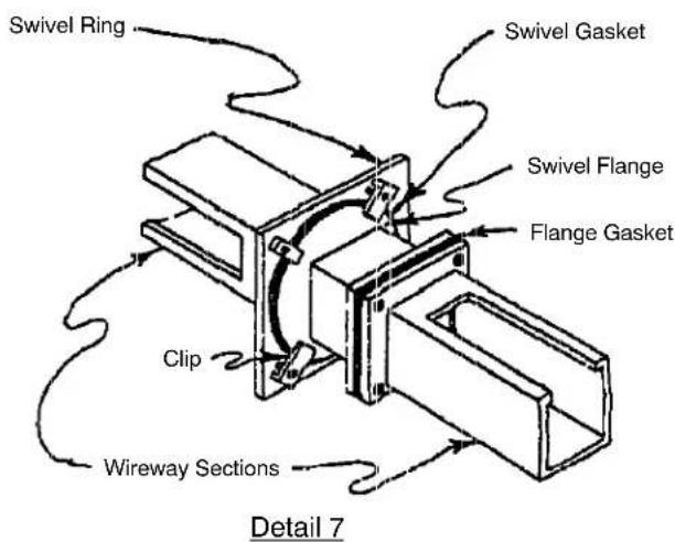
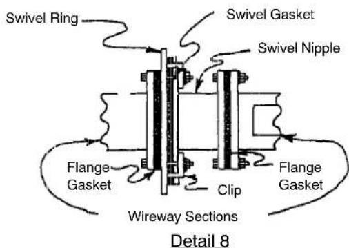
A. To Install 2.5 X 2.5 And 4 X 4 Regular Type Swivel Nipple:
1. Position wireway section, flange gasket, swivel ring, round swivel gasket, and swivel nipple in that order. (see details 7 and 8) Position clips over round flange of swivel nipple, and install screws and nuts.
B. To Install 6 × 6 and 8 × 8 Regular Type Swivel Nipple:
1. Position wireway section, flange gasket, and swivel ring in that order. (see details 7 and 8) Attach swivel ring to wireway flange with four flat-head screws and nuts. Position round swivel gasket and swivel nipple on swivel ring. Position clips over round flange of swivel nipple and install screws and nuts.
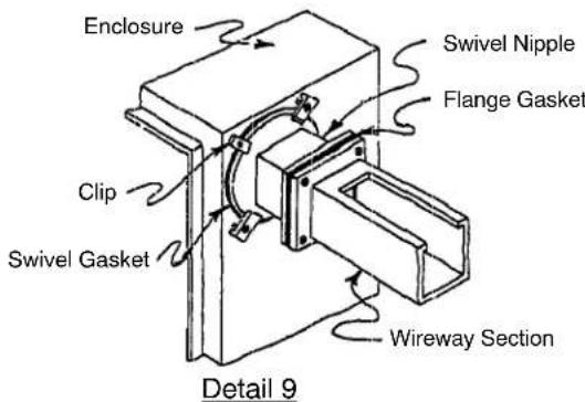
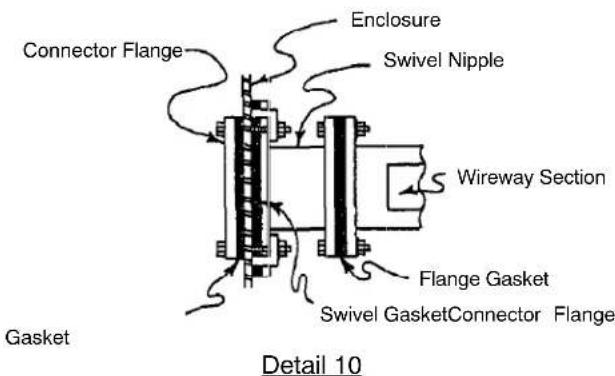
C. To Install Box Entry Type Swivel Nipple:
- Using the provided connector flange as a pattern, trace the box entry cutout on the outside of the enclosure and make the cutout.
- Position the connector flange and the connector flange gasket on the inside of the enclosure as shown in detail 10. Then position the round swivel gasket and the swivel nipple on the outside of the enclosure as shown in details 9 and 10. Position the clips over the round flange of the swivel nipple, and install the screws and nuts.
3ENGLISH
Installation Instructions Feed-Through Wireway
VI. BOX ENTRIES (WITHOUT SWIVEL NIPPLE): When entering a control enclosure or box with regular wireway, make a cutout in the enclosure as shown in detail 11. The box connector and a gasket are positioned inside the enclosure, while another gasket is placed between the outside surface of the enclosure and the adjoining wireway section. See detail 12 for the proper arrangement.
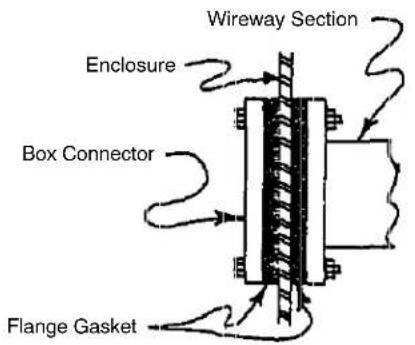
Detail 12
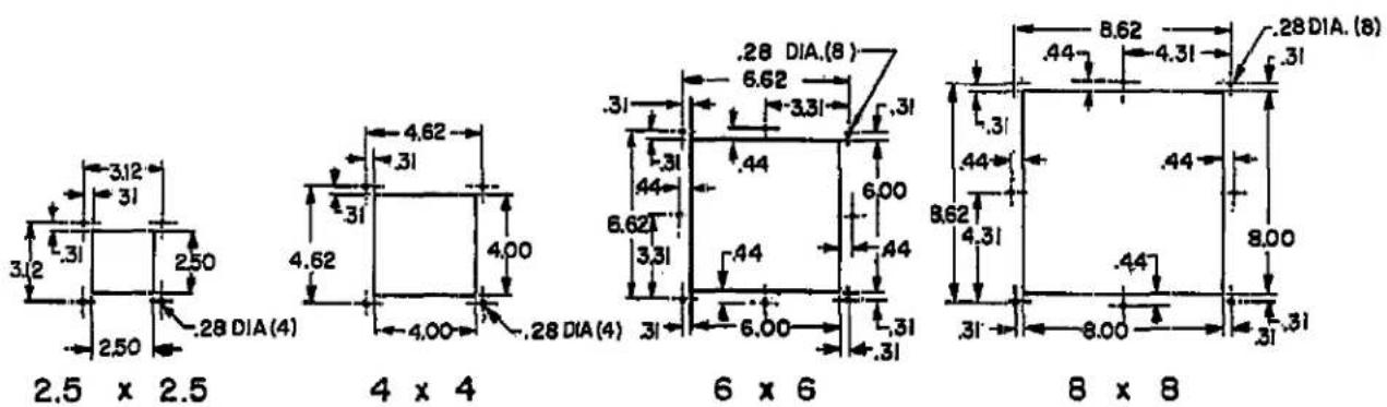
Detail 11 Units: Inch
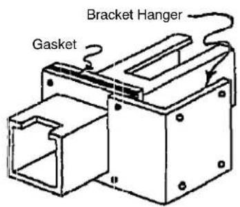
VII. HANGERS: Assemble hangers as shown in details 13 and 14. Note that the hanger does not fit between the adjacent wireway flanges. These hangers may be attached to the wireway flange in various positions.
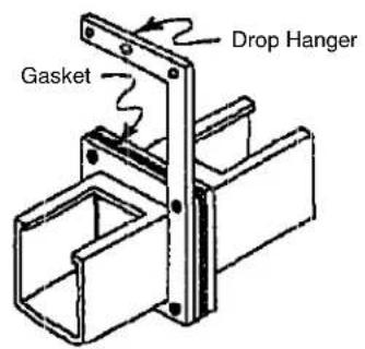
Detail 13
Detail 13
4DEUTSCH
Instructions d-installation
Hoffman Enclosures Inc.
2100 Hoffman Way
Anoka, MN 55303, 1745
(763)422-8011
www.hoffmanonline.com
Pentair Electronic Packaging
170 Commerce Drive
Wenfield, PA 28786
(401)732-3770
www.pentair-ep.com
Mexico
Pentair Enclosures, S. de R.L. de C.V.
Fedenoo T. de la Chica No. 8 Piso 4 A Ciguita, Compostela, Spain
Circulo Comercial Plaza Satele Cuiad Satete
Naucalpan, Mexico C.P. 53100
011-52-55-5393-8263
Canada
Hoffman-Schroff 111
111 Grangeway Avenue, Suite 504
Santacruz, Guatemala M11U350
Sunlight, OHLAND WHTT SCS (416)289-2770
1-800-668-2500 (Canada only)
Germany
Schroff GmbH
01-6871 German Centre
25 International Business Park 21
Singapore 609916 65.528.78.00
Japan
Schroff KK
Nisso No.13 Bldg.4F
2-5=1 Shinyok 长江
Konoku-Ku, Yokohama shi
Korosawa-202, 2037
81.047547600.01
Finland
Schroff Scandinavia AB
Perasimentie 8
03100 Nummela
358092226800
Norway
Schroff Scandinavia AB
Bjoermeruchveien 24
12650910
47022763360