
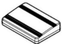
AVICEVO1 - GPS Navigation System PIONEER - Free user manual and instructions
Find the device manual for free AVICEVO1 PIONEER in PDF.

| Product type | GPS navigation system |
| Brand | Pioneer |
| Model | AVICEVO1 |
| Power supply | 12 V DC (vehicle battery), 10 A fuse |
| Main functions | GPS navigation, audio/video playback, iPod/iPhone/Android connection, rear view camera, AUX input, rear video output |
| Connectivity | USB1 and USB2 ports, rear view camera input, RCA audio/video outputs, GPS antenna, external microphone |
| Supplied parts | Panel control cable, USB and AUX cable, power cord, GPS antenna, vehicle adapter, adapter cable, antenna conversion cable, USB identification labels |
| Mobile device compatibility | iPhone (Lightning and 30-pin), iPod, Android devices (USB-C) |
| Rear view camera | Dedicated input (RCA), automatic switching in reverse gear |
| Rear video output | RCA connector for rear display (passengers) |
| Safety | Parking brake lock for certain functions, detailed safety warnings |
| Installation | Recommended by a Pioneer authorized professional |
| Maintenance and cleaning | Clean with a soft dry cloth, avoid chemicals and moisture |
| Operating temperature | -10 °C to +60 °C (estimate) |
| GPS antenna | Passive GPS antenna with metal plate, non-modifiable cable |
| Microphone | External microphone included, installation on sun visor or steering column |
| Dimensions (approx.) | 178 x 100 x 50 mm (estimate 2 DIN) |
| Weight (approx.) | 1.2 kg (estimate) |
| Manual languages | FR, DE, EN, ES, IT, NL, and possibility of translation |
| User rating | 8.0/10 (based on reviews) |
Frequently Asked Questions - AVICEVO1 PIONEER
User questions about AVICEVO1 PIONEER
0 question about this device. Answer the ones you know or ask your own.
Ask a new question about this device
Download the instructions for your GPS Navigation System in PDF format for free! Find your manual AVICEVO1 - PIONEER and take your electronic device back in hand. On this page are published all the documents necessary for the use of your device. AVICEVO1 by PIONEER.
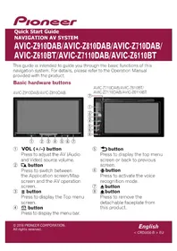
USER MANUAL AVICEVO1 PIONEER
Precautionsbeforeconnectingthe system5
Beforeinstallingthisproduct5
Topreventdamage6
-Noticefortheblue/whitelead6
Partssupplied7
Connectingthepowercord8
Descriptionofthecolouredcables9
Connectingthesystem10
Connectingthemainunittotheface panel11
Connectingtoseparatelysoldpower amp12
ConnectinganiPod/iPhoneoranAndroid device13
Attaching identification labelstoUSB cables14
ConnectinganiPhonewithLightning connector14
-ConnectingviatheUSBport (iPhone)14
ConnectinganiPhonewith30-pin connector15
-ConnectingviatheAUXinput (iPhone)15
ConnectingtheAndroid™ device15
Connectingarearviewcamera16
UsinganAUXinput17
Connectingthereardisplay18
-When using areardisplayconnectedto rearvideooutput18
03 Installation
Precautionsbeforeinstallation19
Toavoidelectromagneticinterference19
Beforeinstalling19
Installingthisproduct20
InstallingtheGPSaerial21
Installingthemicrophone22
04 Afterinstallation
Afterinstallingthisproduct23
Yournewproductandthis manual
- Thenavigationfeaturesofthisproduct (andtherearviewcameraoptionifpur-chased)areintendedsolelytoaidyouin theoperationofyourvehicle.Itisnotasub-stituteforyourattentiveness,judgement andcarewhendriving.
- Neverusethisproducttoroutetohospitals,policestations,orsimilarfacilitiesin anemergency.Pleasecalltheappropriate emergencynumber.
- Donotoperatethisproduct,anyapplications,ortherearviewcameraoption(ifpurchased)ifdoingsowilldivertyourattention inanywayfromthesafeoperationofyour vehicle.Alwaysobservesafedrivingrules andfollowallexistingtrafficregulations.If youexperienceddifficultyinoperatingthis productorreadingthedisplay,parkyour vehicleinasafelocationandapplythe handbrakebeforemakingthenecessary adjustments.
- Thismanualeexplainshowtoinstallthis productinyourvehicle.Operationofthis productisexplainedintheseparatemanuals.
- Donotinstallthisproductwhereitmay(i) obstructthedriver'svision,(ii)impairthe performanceofanyofthevehicle'soperatingsystemsofsafetyfeatures,including airbags,hazardlampbuttons,or(iii)impair thedriver'sabilitytosafelyoperatethevehicle.Insomecases,itmaynotbepossible toinstallthisproductbecauseofthevehicletypeortheshapeofthevehicleinterior.
• Thegraphicalsymbol ____ placed on theproductmeansdirectcurrent.
Important safeguards
WARNING
Pioneerdoesnotrecommendthatyouinstall thisproductyourself.Thisproductisdesignedforprofessionalinstallationonly.We recommendthatonlyauthorisedPioneerservicepersonnel,whohavespecialtraining andexperienceinmobileelectronics,setup andinstallthisproduct.NEVERSERVICE THISPRODUCTYOURSELF.Installingor servicingthisproductanditsconnecting cablesmayexposeyoutotheriskofelectric shockorotherhazards,andcancausedamagetothisproductthatisnotcoveredby warranty.
CAUTION
Toprotectyourhandsfromcut-woundaccidents, besuretowearcutresistantglovesduringinstallation.
- Readthismanualfullyandcarefullybefore installingthisproduct.
- Keep this manual handy for future reference.
- Paycloseattentiontoallwarningsinthis manualandfollowtheinstructionscarefully.
- Thisproductmayincertaincircumstances displayinaccuratepositionofyourvehicle, thedistanceofobjectsshownonthe screen,andcompassdirections.Inaddition,thesystemhascertainlimitations,includingtheinabilitytoidentifyone-way streets,temporarytrafficrestrictionsand potentiallyunsafedrivingareas.Pleaseexerciseyourownjudgementinthelightof actualdrivingconditions.
Precautions
- Aswithanyaccessoryinyourvehicle'sinterior, thisproductshouldnotdivertyourattentionfromthesafeoperationofyourvehicleasitmayresultinseriousinjuryordeath. Ifyouexperienceddifficultyinoperatingthesystemorreadingthedisplay, pleasemakeadjustmentswhilesafelyparked.
- Pleaseremembertowearyourseatbeltat alltimeswhileoperatingyourvehicle.If youareinanaccident,yourinjuriescanbe considerablymoresevereifyourseatbelt isnotproperlyfastened.
- Certaincountryandgovernmentlawsmay prohibitorrestricttheplacementanduse ofthisproductinyourvehicle.Pleasecomplywithallapplicablelawsandregulations regardingtheuse,installationandoperationofthisproduct.
Precautionsbefore connectingthesystem

WARNING
Donottakeanystepstotamperwithordisablethehandbrakeinterlocksystemwhich isinplaceforyourprotection.Tampering withordisablingthehandbrakeinterlock systemcouldresultinseriousinjuryor death.

CAUTION
- If you decide to perform the installation yourself, and have special training and experience in them mobile electronics installations, please carefully follow all of the steps in the installation manual.
- Secureallwiringwithcableclampsorelectricaltape.Donotallowanybarewiringtoremainexposed.
- Donotdirectlyconnecttheyellowleadof thisproducttothevehiclebattery.If the leadisdirectlyconnectedtothebattery, enginevibrationmayeventuallycause theinsulationtofailatthepointwhere thewirepassesfromthepassengercompartmentintotheenginecompartment.If theyellowlead'sinsulationtearsasaresultofcontactwithmetalparts,short-circuitingcanoccur,resultingin considerabledanger.
- Itisextremelydangeroustoallowcables tobecomewoundaroundthesteeringcolumnorgearstick.Besuretoinstallthis product,itscables,andwiringawayin suchsothattheywillnotobstructorhinderdriving.
- Makesurethatthecablesandwireswill notinterferewithorbecomecaughtin anyofthevehicle'smovingparts,especiallythesteeringwheel,gearstick,handbrake,slidingseattracks,doors,oranyof thevehicle'scontrols.
- Donotroutewireswheretheywillbeexposedtohightemperatures.Iftheinsulationheatsup,wiresmaybecome
damaged, resulting in an short circuit or malfunction and permanent damage to the product.
- DonotcuttheGPSaerialcabletoshortenitoruseanextensiontomakeitlonger. Alteringtheaerialcablecouldresultina shortcircuitormalfunction.
- Donotshortenanyleads.Ifyoudo,the protectioncircuit(fuseholder,fuseresistororfilter,etc.)mayfailtoworkproperly.
- Neverfeedpowertootherelectronicproductsbycuttingtheinsulationofthe powersupplyleadofthisproductandtappingintothelead.Thecurrentcapacityof theleadwillbeexceeded,causingoverheating.
Beforeinstallingthisproduct
- Use this product with a 12-volt battery and negative earthing only. Failure to dosomay result in a fireormal function.
- To avoid shortsin the electrical system, be suretodisconnectthe(-)batterycablebeforeinstallation.
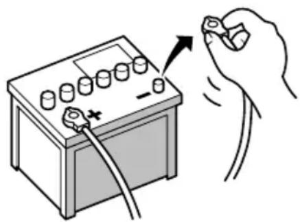
natural_image
Illustration of a hand holding a battery with a switch and plug, no text or symbols present
Topreventdamage

WARNING
- Usespeakersover50W(maximuminput power)andbetween4Ωto8Ω(impedancevalue).Donotuse1Ωto3Ωspeakersforthisproduct.
- Theblackleadisearth.Pleaseearththis leadseparatelyfromtheearthofhigh-currentproductssuchaspoweramps.Donot earthmorethanoneproducttogether withtheearthfromanotherproduct.For example,youmustseparatelyearthany ampunitawayfromtheearthofthisproduct.Connectingearthstogethercan causeafireand/ordamagetheproductsif theirearthsbecamedetached.
-
Whenreplacingthefuse,besuretoonly useafuseoftheratingprescribedonthis product.
-
Whendisconnectingacon connector, pull the connectoritself. Donotpullthelead, as youmaypullitoutoftheconnector.
- ThisproductcannotbeinstalledinvehiclewithoutACC(accessory)positionontheignitionswitch.
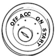
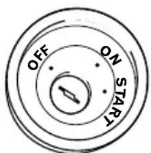
ACCpositionNoACCposition
• To avoid short-circuiting, cover the disconnected lead with insulating tape. It is especially important to insulate all unused speaker leads, which if left uncovered may cause short circuit.
- Attachtheconnectorsofthesamecolour tothecorrespondingcolouredport,i.e., blueconnectortotheblueport,blackto black,etc.
- Refertotheowner'smanualfordetailson connectingthepowerampandotherunits, thenmakeconnectionsaccordingly.
- SinceauniqueBPTLcircuitisemployed, donotdirectlyearththe⊖sideofthe speakerleaderconnectthe⊖sideofan-othersideofthespeakerleadtogether.Be suretoconnectthe⊖sideofthespeaker leadtothe⊖sideofthespeakerleadon thisproduct.
Noticefortheblue/whitelead

Important
Whenthisproductisin"PowerOFF"mode,the controlsignalisalsoturnedoff.If"PowerOFF" modeiscancelled,thecontrolsignalisoutput againandtheaerialisextendedwiththeautoaerialfunction(iftheaerialisbeingused).Becareful sothattheextendedaerialdoesnotcomeinto contactwithanyobstacles.
- Whentheignitionswitchisturnedon(ACC ON),acontrolsignalisoutputthroughthe blue/whitelead.Connecttoanexternal poweramp'ssystemremotecontrolterminal,theauto-aerialrelaycontrolterminal,ortheaerialboosterpowercontrolterminal(max.300mA12VDC).Thecontrolsignal isoutputthroughtheblue/whitelead,even iftheaudiosourceisswitchedoff.
- Besurenottousethisleadasthepower supplyleadfortheexternalpoweramps. Suchconnectioncouldcauseexcessive currentdrainandmalfunction.
- Besurenottousethisleadasthepower supplyleadfortheauto-aerialoraerial booster.Suchconnectioncouldcauseexcessivecurrentdrainandmalfunction.
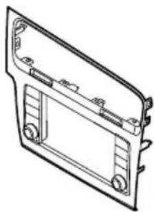
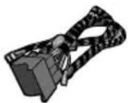
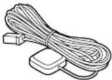
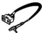
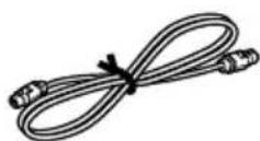
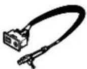
Partssupplied
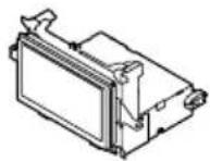
Mainunit(*1)Facepanel(*1)
natural_image
Technical line drawing of a mechanical component with mounting holes and internal brackets (no text or symbols)
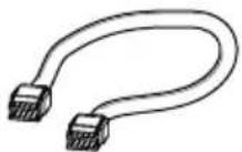
Controlcableforface panel(*2)
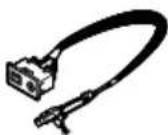
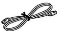
USBandAUXcable (*3)
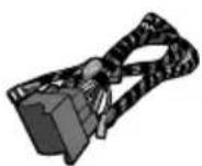
PowercordGPSaerial
natural_image
Illustration of a black cable with a connector and a mechanical clamp (no text or symbols)MicrophoneUSBcable

(2pcs.)
VehicleadapterCableforvehicleadapter

flowchart
graph TD
    A["PORT1"] --> B["PORT2"]
    B --> C["PORT3"]
    C --> D["PORT4"]
AerialconversioncableUSBcableidentifica-
tionlabels

Notes
- (*1)The figureshownisanexample. Themain unitandpanelshapesvarydependingonthe vehicletype.(Forcertainvehicletypes,the facepanelisinitiallyattachedtothemain unit.)
• (*2)Connectthecontrolcablebetween the facepanelandthemainunit.(Forcertainvehicletypes,itisinitiallyconnected.)
• (*3)The figureshownisanexample. The cableshapevariesdependingonthevehicle type.(Forcertainvehicletypes,thereisno terminalcover.)
Connectingthepowercord
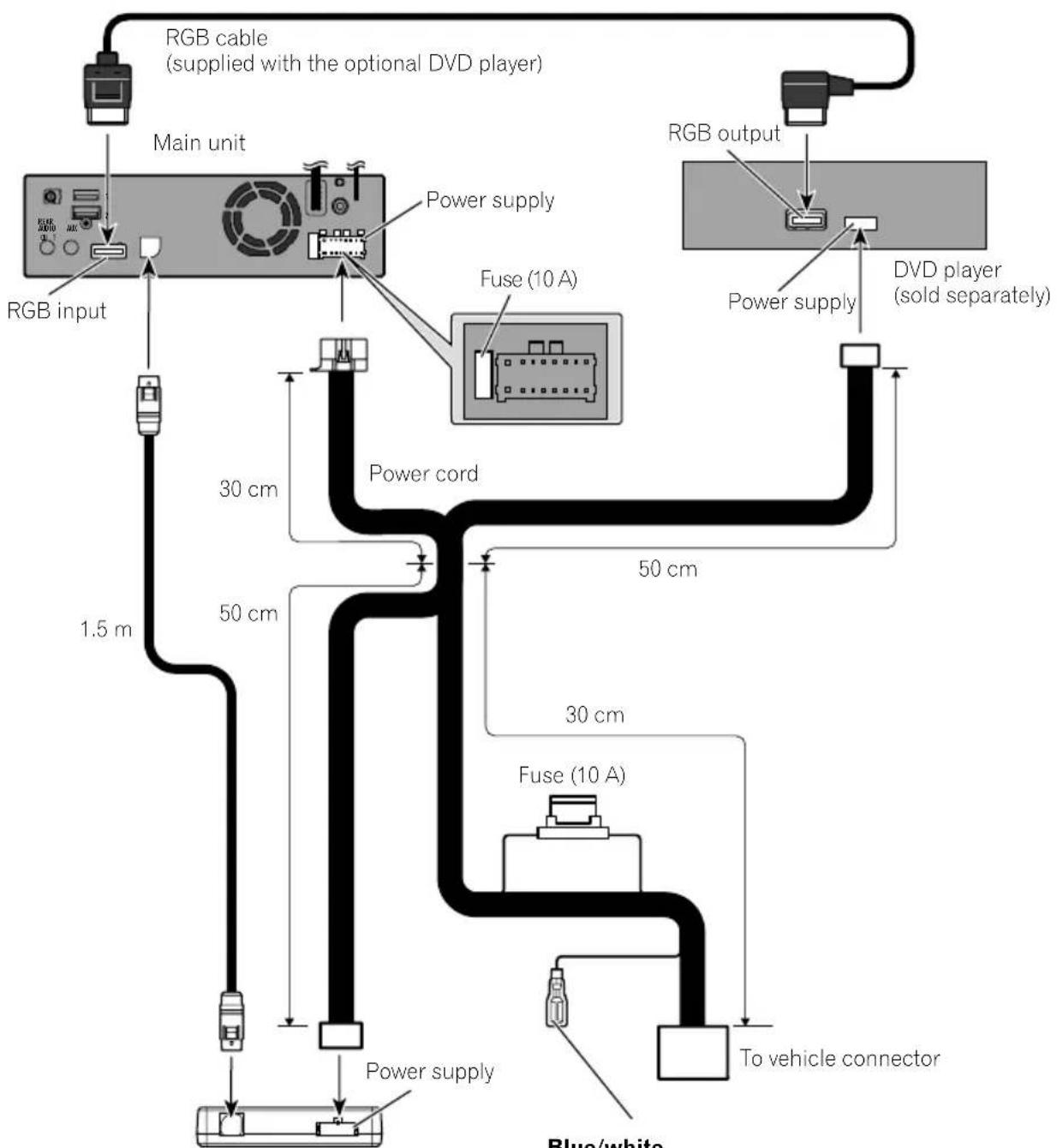
flowchart
graph TD
    A["RGB input"] --> B["Main unit"]
    B --> C["RGB cable (supplied with the optional DVD player)"]
    C --> D["Fuse (10 A)"]
    D --> E["DVD player (sold separately)"]
    E --> F["RGB output"]
    F --> G["Power supply"]
    G --> H["Power cord"]
    H --> I["Blue/white"]
    H --> J["30 cm"]
    H --> K["50 cm"]
    H --> L["1.5 m"]
    H --> M["30 cm"]
    H --> N["Fuse (10 A)"]
    N --> O["To vehicle connector"]
Vehicle adapter
Blue/white
To auto-aerial relay control terminal or aerial booster power control terminal (max. 300 mA 12 V DC).

Descriptionofthecolouredcables
Multiplecolouredcablesareboundtogetherinabundle.Thefunctionofeachcolouredcableisasfollows.
| ColourFunctions | |
| YellowBack-up | |
| RedAccessory | |
| Orange/Whitellumination | |
| Black(earth)Earth | |
| WhiteFrontspeaker(left,+) | |
| White/blackFrontspeaker(left,−) | |
| GreyFrontspeaker(right,+) | |
| Grey/blackFrontspeaker(right,−) | |
| GreenRearspeaker(left,+) | |
| Green/blackRearspeaker(left,−) | |
| VioletRearspeaker(right,+) | |
| Violet/black | Rearspeaker(right,−) |
| PinkThisproductisconnected | heretodetectthedistancethevehicletravels. |
| Lightgreen | UsedtodetecttheON/OFFstatusof thehandbrake. |
| Violet/white | Thiscablehastobeproperlyconnectedsothatthisproductcandetectwhetherthe vehicleismoving forwardsorbackwards.Checkwhetherthevoltageofthiscable changeswhenthereversegearisengaged.Whenyouusearear viewcamera,properconnectionofthisleadisnecessary.Other-wise,youcannotswitchtotherear viewcameraimage. |

WARNING
IMPROPERCONNECTION OFPINK LEADMAY RESULTIN SERIOUSDAMAGEOR INJURY INCLUDING ELECTRICALSHOCK, ANDINTERFERENCE WITH THE OPERATION OF THE VEHICLE SANTILOCKBRAKINGSYSTEM, AUTOMATIC GEARBOXANDSPEEDOMETER INDICATION.

WARNING
LIGHTGREEN LEADATPOWERCONNECTORIS DESIGNED TO DETECTPARKEDSTATUSAND MUSTBE CONNECTED. IMPROPER CONNECTION OR USE OF THIS LEAD MAY VIOLATE APPLICABLE LAW AND MAY RESULT INSERIOUS INJURY OR DAMAGE.
Connectingthesystem
flowchart
graph TD
    A["Main unit"] --> B["GPS aerial input"]
    B --> C["Microphone"]
    B --> D["DAB aerial input"]
    B --> E["Aerial jack"]
    E --> F["Aerial conversion cable"]
    F --> G["Blue/white to aerial conversion cable"]
    G --> H["Vehicle aerial"]
    I["GPS aerial"] --> J["3.55 m"]
    K["Blue/white"] --> L["3 m"]
    M["Aerial supply"] --> N["Power cord"]
    O["Aerial conversion cable"] --> P["Aerial jack"]

WARNING
- To avoid the risk of accident and the potential violation of applicable laws, this product should never be used while the vehicle is being driven except for navigation purposes. And, also rear displays should not be in a location where it is a visible distraction to the driver.
- In some countries, the viewing of images on a display inside a vehicle even by persons other than the driver may be illegal. Where such regulations apply they must be obeyed and this product's video source should not be used.

Connection
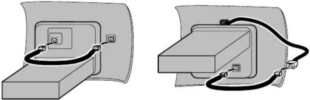
Connectingthemainunittothefacepanel
To operate the main unit using the button on the face panel, the control cable between the face panel and the main unit must be connected. (For certain vehicle types, it is initially connected.)
Thepositionoftheconnectoronthemainunitvariesdependingonthevehicletype.
natural_image
Two technical diagrams showing cable connections between a device component (no text or symbols present)
Connectingtoseparatelysoldpoweramp
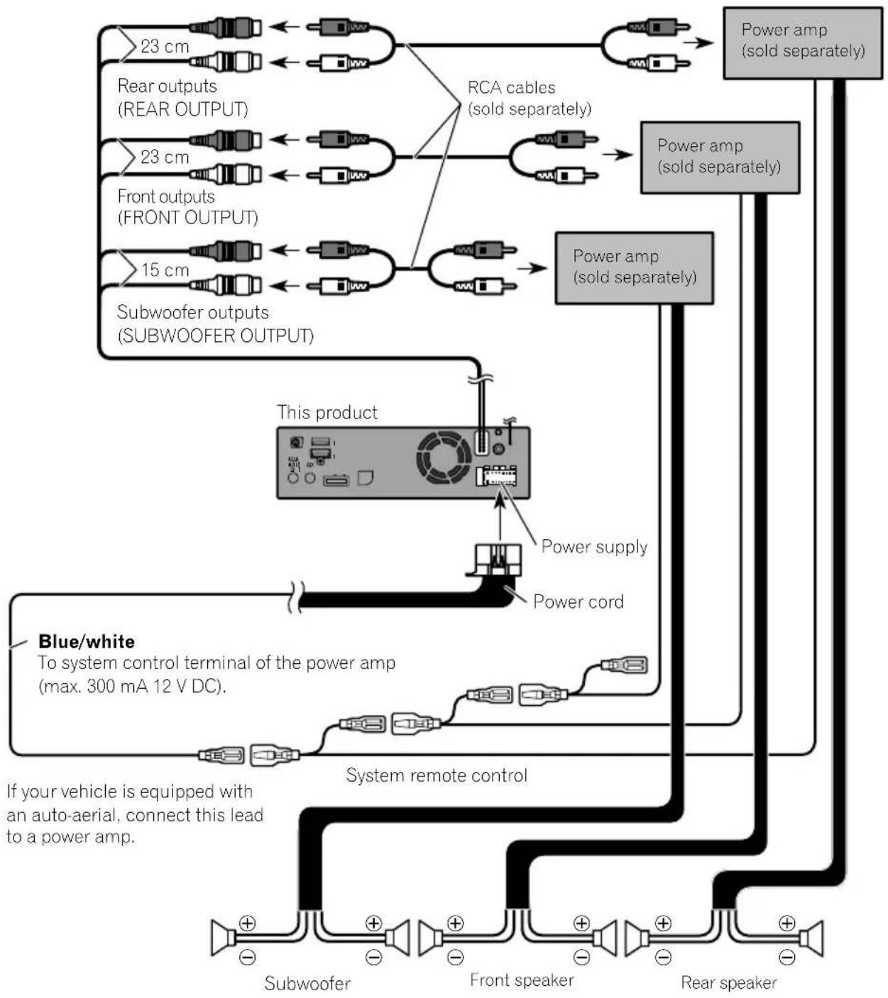
flowchart
graph TD
    A["23 cm"] --> B["Rear outputs (REAR OUTPUT)"]
    C["23 cm"] --> D["Front outputs (FRONT OUTPUT)"]
    E["15 cm"] --> F["Subwoofer outputs (SUBWOOFER OUTPUT)"]
    B <--> G["RCA cables (sold separately)"]
    D <--> G
    F <--> G
    G --> H["Power amp (sold separately)"]
    H --> I["Power cord"]
    I --> J["Power supply"]
    J --> K["This product"]
    K --> L["Blue/white To system control terminal of the power amp (max. 300 mA 12 V DC)."]
    L --> M["System remote control"]
    M --> N["Subwoofer"]
    M --> O["Front speaker"]
    M --> P["Rear speaker"]
    style A fill:#f9f,stroke:#333
    style C fill:#f9f,stroke:#333
    style E fill:#f9f,stroke:#333
    style K fill:#ccf,stroke:#333
    style M fill:#cfc,stroke:#333

Notes
- You can change the RCA output of the subwoofer depending on your subwoofer system. (Refer to Operation Manual.)
· The subwoofer output of this product is monaural.

Connection
ConnectinganiPod/iPhoneoranAndroiddevice
Findyourdeviceandthefunctionyouwanttooperatefromthelistbelow,andrefertothepagefortheconnection.
☐Dependingonthedevice, somefunctionsmaynotbeavailable.
iPhone(5,5c,5s,6,6Plus)/iPodtouch(5thgeneration)/iPodnano(7thgeneration)
RefertoConnectingviatheUSBport(iPhone)onpage14.
iPhone3GS/iPodtouch(2nd,3rdgeneration)/iPodclassic(80GB,160GB)/iPodnano(3rd,4th,5th,6thgeneration)/iPhone(4,4s)/iPodtouch(4thgeneration)
RefertoConnectingviatheAUXinput(iPhone)onpage15.
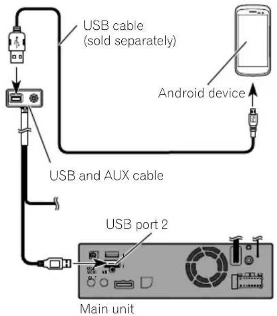
Androiddevice
| RefertoConnectingtheAndroid | TM | deviceonpage15. |
ConnecteddevicesAvailableUSBport
iPhone(WithAppleCarPlay)USB1
| iPhone/iPod (Without Apple CarPlay) | USB1 or USB2 |
AndroiddeviceUSB2
USBstoragedeviceUSB1orUSB2
WhenusingAppleCarPlay,connecttheiPhonetoUSBport1.
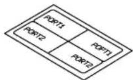
Attachingidentification labelstoUSBcables
AttachidentificationlabelstoUSBcablesbeforeinstallingthisproductinavehicle.
1ConnectUSBcablestotheUSBport1 and2ontherearofthisproduct.
2AttachtheidentificationlabelscorrespondingtoeachporttotheUSBcablesas illustratedbelow.
Attachthe"PORT1"labeltotheUSBcable connectedtotheUSBport1. Attachthe"PORT2"labeltotheUSBcable connectedtotheUSBport2.

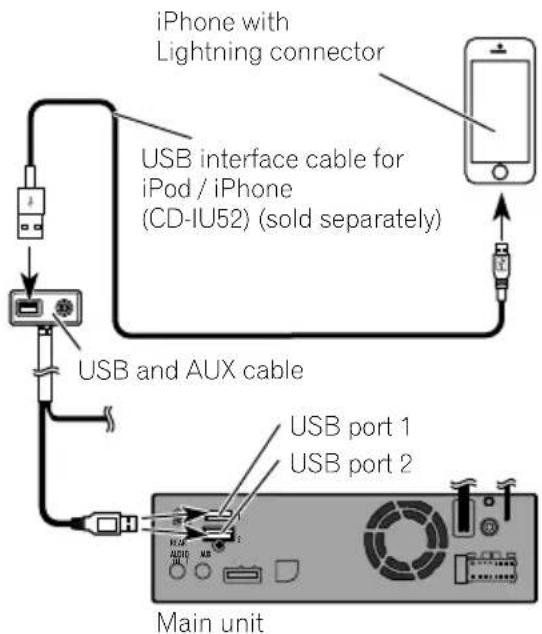
ConnectinganiPhonewith Lightningconnector

Notes
- Fordetailsonhowtoconnectanexternaldeviceusingaseparatelysoldcable, refertothe manualforthecable.
- Fordetailsconcerningtheconnection,operationsandcompatibilityofiPhone,refertoOperationManual.
ConnectingviatheUSBport (iPhone)
TheUSBinterfacecableforiPod/iPhone(CD-IU52)(soldseparately)isrequiredfortheconnection.
□WhenusingAppleCarPlay,connectthe iPhonetoUSBport1.

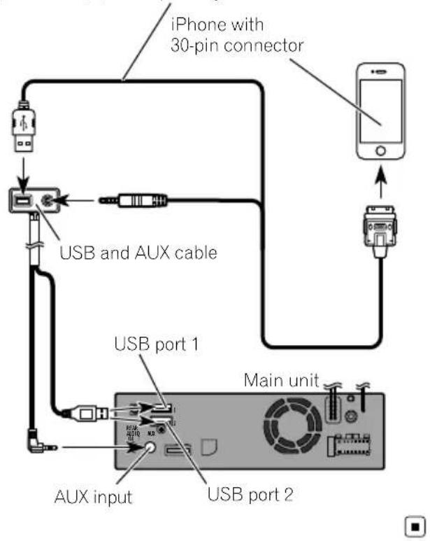
ConnectinganiPhonewith 30-pinconnector

Notes
- Fordetailsonhowtoconnectanexternaldeviceusingaseparatelysoldcable, refertothe manualforthecable.
- Fordetailsconcerningtheconnection,operationsandcompatibilityofiPhone,refertoOperationManual.
ConnectingviatheAUXinput (iPhone)
TheUSBinterfacecableforiPod/iPhone(CD-IU201V)(soldseparately)isrequiredforthe connection.
USB interface cable for iPod / iPhone (CD-IU201V) (sold separately)
ConnectingtheAndroid ^TM device

Notes
- FordetailsconcerningtheconnectionandoperationsofAndroiddevice,refertoOperation Manual.
- Fordetailsonhowtoconnectanexternaldeviceusingaseparatelysoldcable, refertothe manualforthecable.
TheUSBinterfacecableforusewithAndroid devices(soldseparately)isrequiredforthe connection.

CAUTION
TheUSBType-Cphonemaynotoperate with somecables.Pleaseusetherecommended cable.
FordetailsabouttherecommendedUSB-Ato USBType-Ccable, pleaserefertoourwebsite.

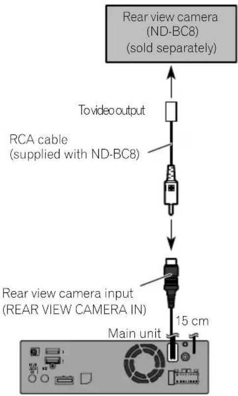
Connectingarearviewcamera
When this product is used with rearview camera, it is possible to automatically switch from the videotorear view image when the gear stick is moved to REVERSE(R). Camera Viewmode also allows you to check what is behind you while driving.

WARNING
USEINPUTONLYFORREVERSEORMIRROR IMAGEREARVIEWCAMERA.OTHERUSEMAY RESULTININJURYORDAMAGE.

CAUTION
- Thescreenimagemayappearreversed.
- Therearviewcameraisusedasanaidto keepaneyontrailers,orbackingintoatight parkingspot.Donotusethisfunctionforentertainmentpurposes.
- Objectsinrearviewmayappearcloseror moredistantthaninreality.
- Pleasenotethattheimageareashownbythe rearviewcameramaydifferslightlywhenfull-screenimagesaredisplayedwhenbacking andwhencheckingtherearofthevehicle whilemovingforward.

Notes
- Thismodeisavailablewhentherearview camerasettingissetto"On".(Fordetails, refertoOperationManual.)
- Connectthisproducttotherearviewcamera only.Donotconnecttoanyother equipment.
UsinganAUXinput
flowchart
graph TD
    A["External video component (sold separately)"] --> B["Toaudio outputs"]
    A --> C["Tovideo output"]
    B --> D["RCA cables (sold separately)"]
    C --> D
    D --> E["USB and AUX cable"]
    E --> F["Mini-jack AV cable"]
    F --> G["Red, white"]
    F --> H["Yellow"]
    F --> I["Main unit"]

Notes
- Thismodeisavailablewhenthesettingof AUX input is set to "On". (For details, refer to OperationManual.)
- Whenconnectinganexternalvideocomponentusingamini-jackAVcable,useaseparatelysoldAUXextensioncableasnecessary.

CAUTION
Besuretouseamini-jackAVcable(soldseparately)forwiring.Ifyouuseothercables,thewiringpositionmightdifferresultingindisturbed imagesandsounds.
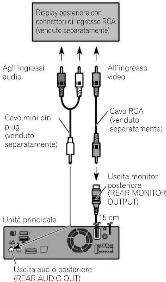
L: Left audio (White)
R : Right audio (Red)
V: Video (Yellow)
G: Earth

Connectingthereardisplay
When using areardisplay connected to rear video output

WARNING
NEVERinstallthereardisplayinalocation that enable sthedrivertowatch the video source while driving.
Thisproduct'srearvideooutputisforconnection ofadisplaytoenablepassengersintherear seatstowatchthevideosource.
Precautionsbefore installation

CAUTION
- Neverinstallthisproductinplaceswhere, orinamannerthat:
—Could injurethedriverorpassengersif thevehiclestopssuddenly.
—Mayinterferewiththedriver'soperationofthevehicle,suchasonthefloorinfrontofthedriver'sseat,orclosetothesteeringwheelorgearstick. - Makesurethereisnothingbehindthe dashboardorpanellingwhendrilling holesinthem.Becarefulnottodamage fuellines,brakelines,electroniccomponents,communicationwiresorpower cables.
- Whenusingscrews, donotallowthemto comeintocontactwithanyelectricallead. Vibrationmaydamagewiresorinsulation, leadingtoashortcircuitorotherdamage tothevehicle.
- Toensureproperinstallation,besureto usethesuppliedpartsinthemannerspecified.Ifanypartsarenotsuppliedwith thisproduct,usecompatiblepartsinthe mannersspecifiedafteryouhavetheparts' compatibilitycheckedbyyourdealer.If partsotherthansuppliedorcompatible onesareused,theymaydamageinternal partsofthisproductortheymaywork looseandtheproductmaybecomedetached.
- Itisextremelydangeroustoallowcables tobecomewoundaroundthesteeringcolumnorgearstick.Besuretoinstallthis product,itscables,andwiringawayin suchsothattheywillnotobstructorhinderdriving.
- Makesurethatleadscannotgetcaughtin adoorortheslidingmechanismofaseat, resultinginashortcircuit.
-
Please confirm the proper function of your vehicle's other equipment after installation of this product.
-
Donotinstallthisproductwhereitmay(i) obstructthedriver'svision,(ii)impairthe performanceofanyofthevehicle'soperatingsystemsorsafetyfeatures,includingairbags,hazardlampbuttonsor(iii)impairthedriver'sabilitytosafelyoperatethevehicle.
- Install this product between the driver's seat and front passenger seat so that it will not be hit by the driver or passenger if the vehicle stops quickly.
- Neverinstallthisproductinfrontofor nexttotheplaceinthedashboard,door, orpillarfromwhichhoneofyourvehicle's airbagswoulddeploy.Pleaserefertoyour vehicle'sowner'smanualforreferenceto thedeploymentareaofthefrontalairbags.
- Failuretofollowalloftheseprecautions mayresultinserious injuryordeath.
Toavoidelectromagnetic interference
Inordertopreventinterference, setthefollowingitemsasfaraspossiblefromthisproduct, othercablesorleads:
• FM, MW/L Waerialanditslead
• DABaerialanditslead
•GPSaerialanditslead
Inaddition, you should lay or route each aerial leads as far as possible from other aerial leads.
Donotbind, layorroutethemtogether, or crossthem. Electromagneticnoisewillincrease the potential for errors in the vehicle's location display.
Beforeinstalling
- Consultwithyournearestdealerifinstallationrequiresdrillingholesorothermodificationsofthevehicle.
- Beforemakingafinalinstallationofthis product, temporarilyconnectthewiringto confirmthattheconnectionsarecorrect andthesystemworksproperly.
Installingthisproduct Installationnotes
- Donotinstallthisproductinplacessubject tohightemperaturesorhumidity,suchas:
—Placesclosetoaheater,ventorairconditioner. —Placesexposedtodirectsunlight,such asontopofthedashboard. —Placesthatmaybeexposedtorain, suchasclosetothedoororonthevehicle'sfloor.
• Install this product in an area a strongen-ought bearits weight. Choose a position where this product can be firmly installed, and install it securely. If this product is not securely installed, the current location of the vehicle cannot be displayed correctly.
- Wheninstalling,toensureproperheatdispersalwhenusingthisproduct,makesureyouleaveamplespacebehindtherearpanelandwrapanyloosecablesssotheyarenotblockingthevents.
- Thecordsmustnotcovertheareashown inthefigurebelow.Thisisnecessaryto allowtheampsandnavigationmechanism todissipateheat.
Donotcoverthisarea.
Fordetailsontheinstallationmethodforeach vehicletype, refertotheseparateinstallation manualandinstall thisproductproperly.

InstallingtheGPSaerial

WARNING
DonotinstalltheGPSaerialoveranysensorsorventsonthedashboardofthevehicle, asdoingsomayinterferewiththeproper functioningofsuchsensorsorventsandmay compromisetheabilityofthemetalsheet undertheGPSaerialtoproperlyandsecurelyaffixtothedashboard.

CAUTION
DonotcuttheGPSaerialleadtoshortenit oruseanextensiontomakeitlonger. Alteringtheaerialcablecouldresultinashortcircuitormalfunctionandpermanentdamage tothisproduct.
Installationnotes
- Theaerialshouldbeinstalledonalevelsurfacewhereradiowaveswillbeblockedas littleaspossible.Radiowavescannotbereceivedbytheaerialifreceptionfromthesatelliteisblocked.
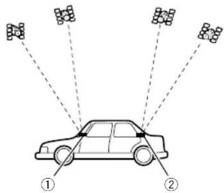
① Dashboard ② Rearshelf
- WheninstallingtheGPSaerialinsidethe vehicle,besuretousethemetalsheetprovidedwithyoursystem.Ifthisisnotused,thereptionsensitivitywillbepoor.
-
Donotcuttheaccessorymetalsheet. This would reduce the sensitivity of the GPS aerial.
-
Themetalsheetcontainsastrongadhesive whichmayleaveamarkonthesurfaceifit isremoved.
• Takecarenottopulltheaerialleadwhen removingtheGPSaerial.Theleadmaybecomedetached. - DonotpainttheGPSaerial,asthismayaffectitsperformance.
- Somemodelsusewindowglassthatdoes notallowsignalsfromGPSsatellitesto passthrough.Onsuchmodels,installthe GPSaerialontheoutsideofthevehicle.
Fordetailsontheinstallationmethodforeach vehicletype, refertotheseparateinstallation manualandinstall thisproductproperly.

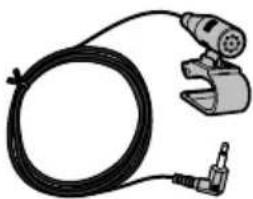
Installingthemicrophone
• Install themicrophone in a place where its direction and distance from the driver make it easiest to pickup the driver's voice.
- Besuretoturnoff(ACCOFF)theproduct beforeconnectingthemicrophone.
- Depending on the vehicle model, the microphone cable length may be too short when you mount the microphone on the sunvisor. In such cases, install the microphone on the steering column.
- Installthemicrophoneonthesunvisor whenitisintheupposition.Itcannotrecognisethedriver'svoiceifthesunvisorisinthedownposition.
Fordetailsontheinstallationmethodforeach vehicletype, refertotheseparateinstallation manualandinstall thisproductproperly.

Afterinstallingthisproduct
1Reconnectthenegative(−)terminalof thevehicle'sbattery.
First, double-check that all connections are correct and that this product is installed correctly. Reassemble all vehicle components that you previously removed. Then reconnect then negative(−) cable to then negative(−) terminal of the battery.
2Starttheengine.
3PresstheRESETbutton.
PresstheRESETbuttononthisproductwitha pointedobjectsuchasthetipofapen.
☐Someofthesettingsandrecordedcontents willnotbereset.
4Changethesettingsasdesired.
Fordetailsconcerningoperations,referto OperationManual.
5 Drivedownanunobstructedroaduntil theGPSstartsreceivingthesignalnormally.

Note
Afterinstallingthisproduct,besuretocheckata safeplacethatthevehicleisperformingnormally.
01 Précautions
natural_image
Illustration of a hand holding a battery with pins and probes, no text or symbols present
natural_image
Technical line drawing of a mechanical component with mounting holes and internal brackets (no text or symbols)Unitéprincipale(*1)Panneaufrontal(*1)

natural_image
Illustration of a handheld device with a black cable and connector (no text or symbols)
MicrophoneCâbleUSB
(2pièces)

natural_image
Two technical diagrams showing electrical connections between a device and a box (no text or symbols present)
Installationdumicrophone
natural_image
Illustration of a hand holding a battery with a pliers, no text or symbols present
Perevitaredanni

AVVERTENZA
natural_image
Technical line drawing of a mechanical component with mounting holes and internal brackets (no text or symbols)Unitàprincipale(*1)Pannellofrontale(*1)

Cavodicontrolloperil pannellofrontale(*2)
CavoUSBeAUX(*3)

natural_image
Illustration of a black cable with a connector and a mechanical clamp (no text or symbols)
MicrofonoCavoUSB
(2pezzi)


natural_image
Two technical diagrams showing electrical connections between components, one with a switch and cable, the other with wires (no text or symbols)
L : Audio lato
sinistro(Bianc
R: Audio lato destro
( Rosso )
V: Video (Giallo)
G: Terra

Collegamentodeldisplay posteriore
①Cruscotto
natural_image
Illustration of a hand holding a battery with a pliers, no text or symbols present
Paraimpedirdaños

ADVERTENCIA

natural_image
Technical line drawing of a mechanical component with mounting holes and internal brackets (no text or symbols)natural_image
Illustration of a handheld device with a black cable and connector (no text or symbols)
MicrófonoCableUSB
(2piezas)


natural_image
Two technical diagrams showing electrical connections between a device and a box (no text or symbols present)
Nocubraestazona.
①Tablerodeinstrumentos
②Bandejatrasera
natural_image
Illustration of a hand holding a battery with pins and probes, no text or symbols present□
ZurVermeidungvonSchäden
WARNING
natural_image
Technical line drawing of a mechanical component with mounting holes and internal brackets (no text or symbols)Haupteinheit(*1)Fronttafel(*1)
natural_image
Illustration of a handheld welding torch and cable (no text or symbols)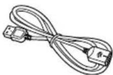
MikrofonUSB-Kabel
(2Stück)


iPhone(5,5c,5s,6,6Plus)/iPodtouch(5.Generation)/iPodnano(7.Generation)
①Armaturenbrett
②Hutablage
natural_image
Illustration of a hand holding a battery with a pliers, showing the switch and battery terminals (no text or symbols)
Voorkomenvan beschadigingen

WAARSCHUWING
ACC-standGeenACC-stand
natural_image
Technical line drawing of a mechanical component with mounting holes and internal brackets (no text or symbols)natural_image
Illustration of a black cable with a tool and connector, no text or symbols present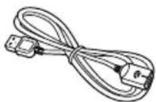
MicrofoonUSB-kabel
(2st.)

natural_image
Two technical diagrams showing electrical connections between a device and a box (no text or symbols present)
L : Audio links (wit)
R: Audio rechts (rood)
V: Video (geel)
G: Aarde

Bedekditgebiedniet.
① Dashboard
②Hoedenplank
28-8, Honkomagome2-chome, Bunkyo-ku,
Tokyo113-0021, JAPAN
PIONEEREUROPENV
Haven1087, Keetberglaan1, B-9120Melsele, Belgium/Belgique
TEL:(0)3/570.05.11
©2016PIONEERCORPORATION.
Allrightsreserved.
©2016PIONEERCORPORATION.
Tousdroitsdereproductionetde
traductionréservés.


- Installation
- Afterinstallation
- Yournewproductandthis manual
- Important safeguards
- WARNING
- CAUTION
- Precautions
- Precautionsbefore connectingthesystem
- Beforeinstallingthisproduct
- Topreventdamage
- Noticefortheblue/whitelead
- Important
- Partssupplied
- Notes
- Connectingthepowercord
- Blue/white
- Descriptionofthecolouredcables
- Connectingthesystem
- Connection
- Connectingthemainunittothefacepanel
- ConnectinganiPod/iPhoneoranAndroiddevice
- Attachingidentification labelstoUSBcables
- ConnectinganiPhonewith Lightningconnector
- ConnectingviatheUSBport (iPhone)
- ConnectinganiPhonewith 30-pinconnector
- ConnectingviatheAUXinput (iPhone)
- ConnectingtheAndroid TM device
- Connectingarearviewcamera
- UsinganAUXinput
- When using areardisplay connected to rear video output
- Precautionsbefore installation
- Toavoidelectromagnetic interference
- Beforeinstalling
- Installingthisproduct Installationnotes
- InstallingtheGPSaerial
- Installationnotes
- Installingthemicrophone
- Afterinstallingthisproduct
- 1Reconnectthenegative(−)terminalof thevehicle'sbattery.
- 2Starttheengine.
- 3PresstheRESETbutton.
- 4Changethesettingsasdesired.
- Drivedownanunobstructedroaduntil theGPSstartsreceivingthesignalnormally.
- Note
- Précautions
- Installationdumicrophone
- Perevitaredanni
- AVVERTENZA
- Collegamentodeldisplay posteriore
- Paraimpedirdaños
- ADVERTENCIA
- ZurVermeidungvonSchäden
- Voorkomenvan beschadigingen
- WAARSCHUWING
- PIONEEREUROPENV
Brand : PIONEER
Model : AVICEVO1
Category : GPS Navigation System