
AEA18CE - Air-conditioner SHARP - Free user manual and instructions
Find the device manual for free AEA18CE SHARP in PDF.
| Product type | Split air conditioner (indoor and outdoor units) |
| Brand and model | Sharp AEA18CE |
| Operating modes | Automatic, Cool, Dry, Fan only, Heat (on models AY-AP18CE/AY-AP24CE) |
| Purification technology | Plasmacluster (clustered ions and negative ions) |
| Remote control | With LCD display, range 7 meters |
| Timers | 1-hour off timer, programmable ON/OFF timer (0.5 to 12 hours) |
| Auto sleep function | Yes (adjusts temperature in Cool/Dry and Heat modes) |
| Airflow direction | Vertical (remote control) and horizontal (manual) |
| Air filters | Washable, cleaning recommended every 2 weeks |
| Service temperature range (Cool) | Indoor: 21–32°C DB, Outdoor: 21–43°C DB |
| Service temperature range (Heat) | Indoor: 20–27°C DB, Outdoor: -8.5–24°C DB (compatible models only) |
| Power supply | Refer to the appliance nameplate (appropriate voltage and frequency) |
| Maintenance | Clean filters, interior of air conditioner, and remote control with a soft cloth |
| Safety | Automatic stop on malfunction, water leakage protection, mandatory grounding |
| Spare parts and repairability | Optional air purifying filter (replace every 3-6 months). Repairs by qualified technician |
| General information | Memory function for settings after power outage. Private use only |
Frequently Asked Questions - AEA18CE SHARP
User questions about AEA18CE SHARP
0 question about this device. Answer the ones you know or ask your own.
Ask a new question about this device
Download the instructions for your Air-conditioner in PDF format for free! Find your manual AEA18CE - SHARP and take your electronic device back in hand. On this page are published all the documents necessary for the use of your device. AEA18CE by SHARP.
USER MANUAL AEA18CE SHARP
natural_image
Illustration of a car air conditioner with a handheld flash unit emitting light (no text or symbols)INDOOR UNIT
ZIMMERGERÄT
UNIT INTERIEURE
UNIDAD INTERIOR
UNITA' INTERNA
UNIDADE INTERIOR
ΕΣΩΤΕΡΙΚΗ ΣΥΣΚΕΥΗ
BINNEN-UNIT
İÇ ÜNİTE
ВНУТРЕННИЙ БЛОК
OUTDOOR UNIT
AUSSENGERÄT
UNIT EXTERIEURE
UNIDAD EXTERIOR
UNITA' ESTERNA
UNIDADE EXTERIOR
ΕΞΩΤΕΡΙΚΗ ΣΥΣΚΕΥΗ
BUITEN-UNIT
DIŞ ÜNİTE
НАРУЖНИЙ БЛОК
AY-AP18CE
AY-AP24CE
AH-AP18CE
AH-AP24CE
AE-A18CE
AE-A24CE
AU-A18CE
AU-A24CE
香港電器安全規格
(國際電工委員會規格適合)
SPLIT TYPE
ROOM AIR CONDITIONER
ZWEITEILIGES
KLIMAGERAT
CLIMATISEUR INDIVIDUEL
EN DEUX PARTIES
MANUAL DE INSTRUÇÕES
Thank you for purchasing a SHARP air conditioner. Please read this manual carefully before operating the product.
CONTENTS
- PRECAUTIONS ......E-1
• ADDITIONAL NOTES ON OPERATION .....E-3
• TIPS ON SAVING ENERGY .....E-3
• PART NAMES.....E-4
• USING THE REMOTE CONTROL .....E-6
• TIPS ABOUT PLASMACLUSTER OPERATION. E-7 - BASIC OPERATION ....E-8
• ADJUSTING THE AIR FLOW DIRECTION .E-10
• PLASMACLUSTER OPERATION ..... E-11
- ONE-HOUR OFF TIMER ...... E-11
• TIMER OPERATION..... E-12
- AUXILIARY MODE ...... E-14
- MAINTENANCE ...... E-14
• OPTION KIT..... E-15
- BEFORE CALLING FOR SERVICE ... E-16
PRECAUTIONS
WARNINGS FOR USE
1 Do not pull or deform the power supply cord. Pulling and misuse of the power supply cord can result in damage to the unit and cause electrical shock.
2 Be careful not to expose your body directly to the outlet air for a long time. It may affect your physical conditions.
3 When using the air conditioner for infants, children, elderly, bedridden, or disabled people make sure the room temperature is suitable for those in the room.
4 Never insert objects into the unit. Inserting objects can result in injury due to the high speed rotation of internal fans.
5 Ground the air conditioner without fail. Do not connect the grounding wire to gas pipe, water pipe, lightning rod or telephone grounding wire. Incomplete grounding may cause electric shock.
6 If anything is abnormal with the air conditioner (ex. a burning smell), stop the operation immediately and turn the circuit breaker OFF.
7 Follow local rules and regulations for power supply cord cabling. Improper cable connection can cause the power supply cord, plug and the electrical outlet to overheat and cause fire.
8 Use only the manufacture-specified power cord for replacement. Replacement should be performed by a qualified technician or a service person.
WARNINGS FOR INSTALLATION / REMOVAL / REPAIR
- Do not attempt to install/remove/repair the unit by yourself. Incorrect work will cause electric shock, water leak, fire etc. Consult your dealer or other qualified service personnel for the installation/removal/repair of the unit.

This equipment complies with the requirements of Directives 89/336/EEC and 73/23/EEC as amended by 93/68/EEC.
PRECAUTIONS
CAUTIONS FOR USE
1 Open a window or door periodically to ventilate the room, especially when using gas appliances. Insufficient ventilation may cause oxygen shortage.
2 Do not operate the buttons with wet hand. It may cause electric shock.
3 For safety, turn the circuit breaker off when not using the unit for an extended period of time.
4 Check the outdoor unit mounting rack periodically for wear and to make sure it is firmly in place.
5 Do not put anything on the outdoor unit nor step on it. The object or the person may fall down or drop, causing injury.
6 This unit is designed for residential use. Do not use for other applications such as in a kennel or greenhouse to raise animals or grow plants.
7 Do not place a vessel with water on the unit. If water penetrates into the unit, electrical insulations may deteriorate and cause electric shock.
8 Do not block the air inlets nor outlets of the unit. It may cause insufficient performance or troubles.
9 Be sure to stop the operation and turn the circuit breaker off before performing any maintenance or cleaning. A fan is rotating inside the unit and you may get injured.
10 Do not splash or pour water directly on the unit. Water can cause electrical shock or equipment damage.
11 This appliance is not intended for use by young children or infirm persons without supervision.
Young children should be supervised to ensure that they do not play with the appliance.
CAUTIONS FOR LOCATION / INSTALLATION
- Make sure to connect the air conditioner to power supply of the rated voltage and frequency.
Use of a power supply with improper voltage and frequency can result in equipment damage and possible fire. - Do not install the unit in a place where inflammable gas may leak. It may cause fire. Install the unit in a place with minimal dust, fumes and moisture in the air.
- Arrange the drain hose to ensure smooth drainage. Insufficient drainage may cause wetting of the room, furniture etc.
- Make sure a leak breaker or a circuit breaker is installed, depending on the installation location, to avoid electrical shock.
ADDITIONAL NOTES ON OPERATION
D.B. = Dry-bulb W.B. = Wet-bulb
- The built-in protective device may prevent the unit from operating when used out of this range.
- Condensation may form on the air outlet if the unit operates continuously in the COOL or DRY mode when humidity is over 80 percent.
WHEN POWER FAILURE OCCURS
This air conditioner has a memory function to store settings when a power failure occurs.
After power recovery, the unit will automatically re-start in the same settings which were active before the power failure, except for timer settings.
If the timers were set before a power failure, they will need to be re-set after power recovery.
NOTES FOR MODELS AY-AP18CE/AY-AP24CE
PREHEATING FUNCTION
In the HEAT operation, the indoor fan may not start for two to five minutes after the unit is turned on to prevent cold air from blowing out of the unit.
DE-ICING FUNCTION
- When ice forms on the heat exchanger in the outdoor unit during the HEAT operation, an automatic de-icer provides heat for about 5 to 10 minutes to remove the ice. During de-icing, the inside and outside fans stop operating.
- After de-icing is completed, the unit automatically resumes operation in the HEAT mode.
HEATING EFFICIENCY
- The unit employs a heat pump that draws heat from the outside air and releases it into the room. The outside air temperature therefore greatly affects the heating efficiency.
- If the heating efficiency is reduced due to low outside temperatures, use an additional heater.
- It takes time to warm up and heat the entire room because of the forced air circulation system.
TIPS ON SAVING ENERGY
Below are some simple ways to save energy when you use your air conditioner.
SET THE CORRECT TEMPERATURE
- Setting the thermostat 1°C higher than the desired temperature in the COOL mode (and 2°C lower in the HEAT mode with models AY-AP18CE/AY-AP24CE) will save approximately 10 percent in power consumption.
- Setting the temperature lower than necessary during cooling operation will result in increased power consumption.
BLOCK DIRECT SUNLIGHT AND PREVENT DRAFTS
- Blocking direct sunlight during cooling operation will reduce power consumption.
- Close the windows and doors during cooling operation (and heating operation with models AY-AP18CE/AY-AP24CE).
SET PROPER AIR FLOW DIRECTION TO OBTAIN THE BEST AIR CIRCULATION
KEEP FILTER CLEAN TO ENSURE THE MOST EFFICIENT OPERATION MAKE MOST OF THE TIMER OFF FUNCTION
DISCONNECT THE POWER CORD WHEN THE UNIT IS NOT USED FOR AN EXTENDED PERIOD OF TIME
- The indoor unit still consumes a small amount of power when it is not operating.
INDOOR UNIT
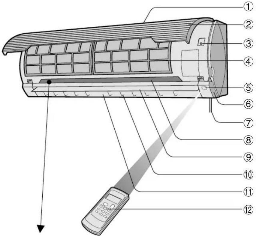

① Inlet (Air)
②Open Panel
③ AUX. Button
④ Air Filters
⑤Receiver Window
⑥ Louvre Unit
Open to clean the inside of the air conditioner.
⑦Power Supply Cord (AY-AP18CE/AH-AP18CEonly)
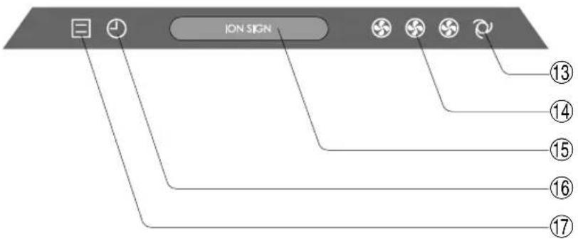
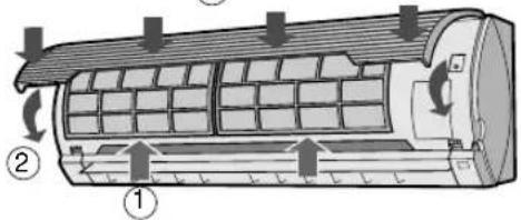
⑧Indicator Panel
⑨Vertical Adjustment Louvres
⑩Horizontal Adjustment Louvres
⑪ Outlet (Air)
⑫ Remote Control
⑬ AUTO FAN SPEED Lamp (green
⑭FAN SPEED Lamp (green
⑮PLASMACLUSTER Lamp (blue, green)
⑯TIMER Lamp (orange Ⓥ)
⑰ OPERATION Lamp (red ☒)
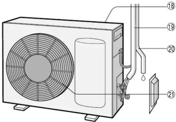
OUTDOOR UNIT
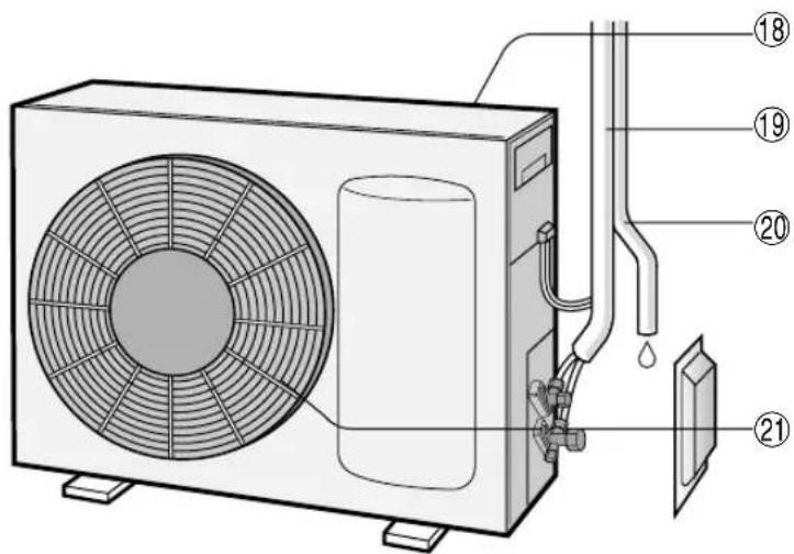
⑱Inlet(Air)
⑲Refrigerant Tube and Interconnecting Cord
⑳Drainage Hose
②1 Outlet(Air)
NOTE: Actual units might vary slightly from those shown above.
REMOTE CONTROL
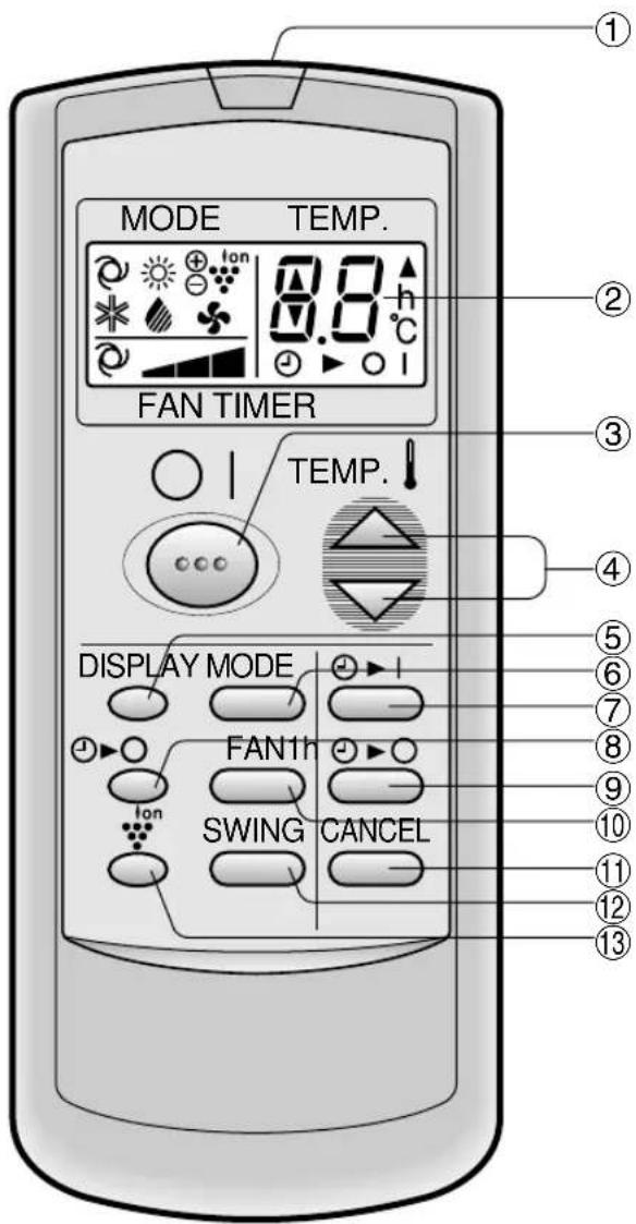
①TRANSMITTER
②DISPLAY (Liquid Crystal Display)
③ON/OFF Button
④ THERMO. (Thermostat) Button
⑤DISPLAY Button
⑥MODE Button
⑦TIMER ON Button (for setting the timer)
⑧ONE-HOUR OFF TIMER Button
⑨ TIMER OFF Button (for setting the timer)
⑩FAN Button
⑪ TIMER CANCEL Button
⑫SWING Button
⑬PLASMACLUSTER Button
(The heat mode symbol 🌿s provided only on models AY-AP18CE/AY-AP24CE)
L.C.D. REMOTE CONTROL DISPLAY
⑭ MODE SYMBOLS

: AUTO : CC


:HEAT:DRF:FAN ONLY

(only for
AY-AP18CE/AY-AP24CE)
⑮FAN SPEED SYMBOLS

: AUTO : Ma

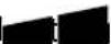
⑯PLASMACLUSTER SYMBOL
⑰ TEMPERATURE AND TIMER COUNT DOWN INDICATOR
⑱TRANSMITTING SYMBOL
⑲TIMER ON/TIMER OFF INDICATOR
Indicates when timer on or timer off is set.
(The heat mode symbol 🌿 is provided only on models AY-AP18CE/AY-AP24CE)
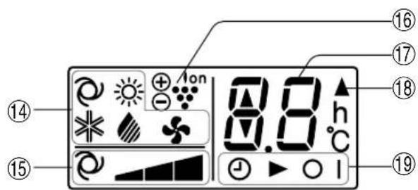
LOADING BATTERIES Use two size-AAA (R03) batteries.
1 Remove the battery cover at the back of the remote control.
2 Insert batteries in the compartment, making sure the ⊕ and ⊖ polarities are correctly aligned.
- Lines will be indicated on the display when batteries are properly installed.
3 Reinstall the battery cover.
natural_image
Technical line drawing of a device with internal components and directional arrows indicating movement (no text or symbols)Battery cover
NOTES:
- The battery life is approximately one year in normal use.
- When you replace the batteries, always change both batteries, and make sure they are the same type.
- If the remote control does not operate properly after replacing the batteries, take out the batteries and reinstall them again after 30 seconds.
- If you will not be using the unit for a long time, remove the batteries from the remote control.
HOW TO USE THE REMOTE CONTROL
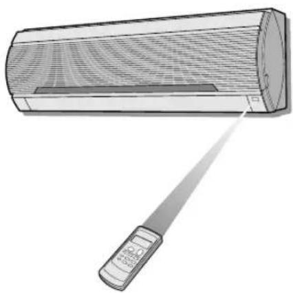
Point the remote control towards the unit's signal receiver window and press the desired button. The unit generates a beep when it receives the signal.
- Make sure there is no curtain or other object between the remote control and the unit.
- The remote control can send signals from up to 7 metres away.
natural_image
Illustration of a wall-mounted air conditioner with a handheld power supply (no text or symbols)
CAUTION
- Do not allow the signal receiver window to receive strong direct sunlight, since it can adversely affect its operation. If the signal receiver window is exposed to direct sunlight, close a curtain to block the light.
- Using a fluorescent lamp with a quick starter in the same room may interfere with transmission of the signal.
- The unit can be affected by signals transmitted from the remote control of a television, VCR or other equipment used in the same room.
- Do not leave the remote control in direct sunlight or near a heater. Also, protect the unit and remote control from moisture and shock which can discolour or damage them.
TIPS ABOUT PLASMACLUSTER OPERATION
The ionizer inside the air conditioner will release cluster ions, which are collective mass of positive and negative ions, into the room.
The cluster ions eliminate airborne mold fungus and deodorize/decompose odor-causing molecules.
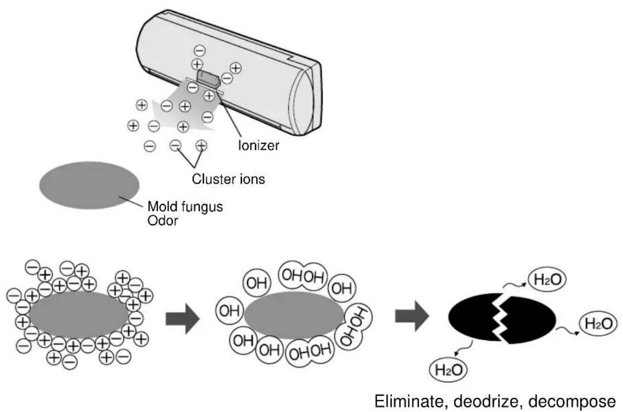
Eliminate, deodrize, decompose
AIR CLEAN OPERATION
Cluster ions released into the air will keep your room air clean.
Negative cluster ions which also exist in natural environment will be released into the air of your room in an increased rate, and help your physical and mental refreshment.
Please refer to page 11 for operation.
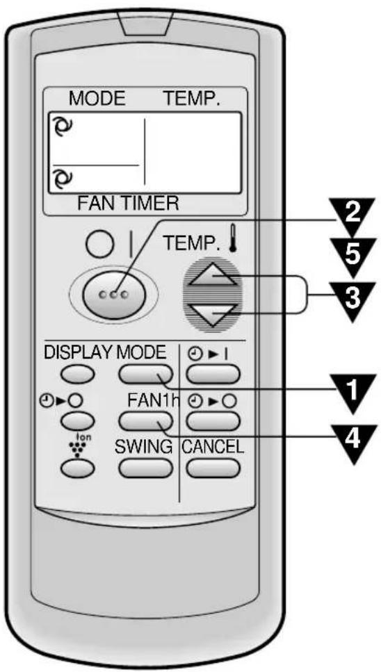

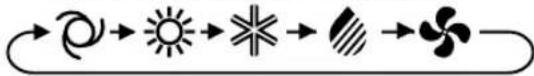
Press the MODE button to select the operation mode.
AUTO HEAT COOL DRY FAN ONLY
flowchart
graph LR
    A["Circle"] --> B["Sun"]
    B --> C["*"]
    C --> D["Diagonal"]
    D --> E["Fleet"]
    E --> F["Circle"]

is only for AY-AP18CE/AY-AP24CE)

Press the ON/OFF button to start operation.
- The red OPERATION lamp ( ☐ on the unit will light.

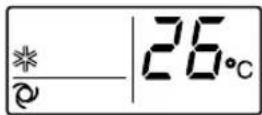
Press the THERMO. button to set the desired temperature.
AUTO/DRY MODE
The temperature can be changed in 1°C increments within the range of 2°C higher to 2°C lower from the temperature automatically determined by the air conditioner.
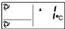
COOL(HEAT for AY-AP18CE/AY-AP24CE)MODE
The temperature can be set within the range of 18 to 32°C.
FAN ONLY MODE
The temperature setting cannot be made.
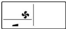

Please the FAN button to set the desired fan speed.
AUTO SOFT LOW HIGH
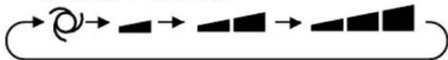
flowchart
graph LR
    A["Start"] --> B["Arrow"]
    B --> C["Arrow"]
    C --> D["Arrow"]
    D --> E["Arrow"]
- In the DRY mode, the fan speed is pre-set to AUTO and cannot be changed.
- In the FAN ONLY mode, the fan speed cannot be set to AUTO.

To turn off the unit, press the ON/OFF button again.
- The red OPERATION lamp ( ☑ on the unit will turn off.
TIPS ABOUT AUTO MODE
In the AUTO mode, the temperature setting and mode are automatically selected according to the room temperature when the unit is turned on.
Modes and Temperature Settings for Models AH-AP18CE/AH-AP24CE
| Room temp. at operation start-up | Automatic Operation | |
| Mode Thermostat Setting | ||
| Below 24°C DRY Room Temp. at start-up | ||
| 24°C-26°C | COOL | 24°C |
| 26°C-28°C | COOL | 25°C |
| Above 28°C COOL | 26°C | |
Modes and Temperature Settings for Models AY-AP18CE/AY-AP24CE
| Room temp. at operation start-up | Automatic Operation | |
| Mode Thermostat Setting | ||
| Below 21°C HEAT | 23°C | |
| 21°C-24°C DRY Room Temp. at start-up | ||
| 24°C-26°C | COOL | 24°C |
| 26°C-28°C | COOL | 25°C |
| Above 28°C COOL | 26°C | |
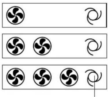
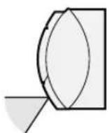
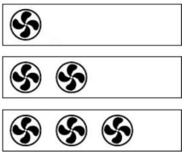
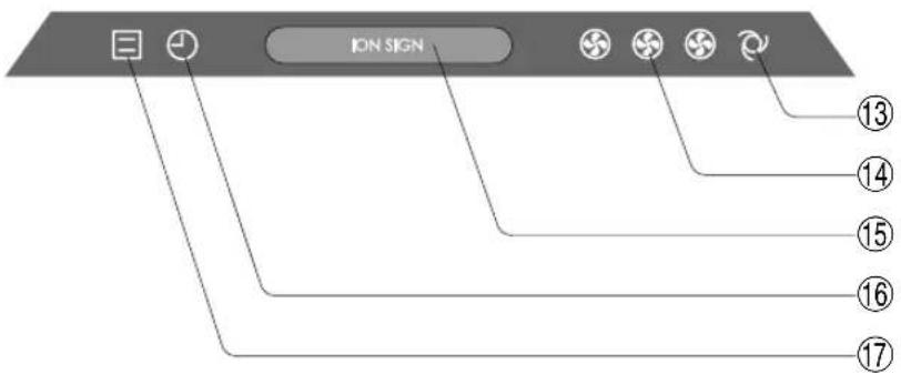
TIPS ABOUT FAN SPEED LAMP
During operation, the FAN SPEED Lamp will light up in 3 levels (2 levels for DRY mode) on the indicator panel of the unit to indicate the fan speed.
When fan speed is set to AUTO When fan speed is set to manual
natural_image
Three rows of circular icons with curved and straight lines, no text or symbols present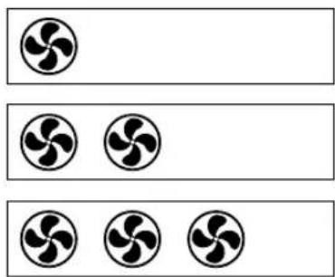
natural_image
Three identical circular diagrams with four blades, arranged horizontally (no text or symbols)Soft speed
Low speed
High speed
The AUTO FAN SPEED Lamp will light up.
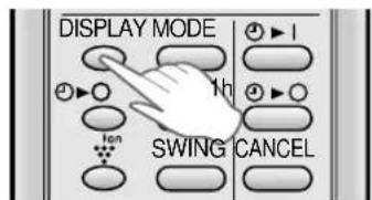
To turn off the FAN SPEED Lamp, press the DISPLAY button. The PLASMACLUSTER Lamp will also go off.
ADJUSTING THE AIR FLOW DIRECTION
VERTICAL AIR FLOW DIRECTION
The air flow direction is automatically preset in each mode as follows for optimum comfort:
| COOL and DRY mode Horizontal air flow | |
| FAN ONLY mode (and HEAT for AY-AP18CE/AY-AP24CE) | Diagonal air flow |
HOW TO ADJUST THE AIR FLOW DIRECTION
Press the SWING button on the remote control once.
• The vertical adjustment louvre will change its angle continuously.
Press the SWING button again when the vertical adjustment louvre is at the desired position.
- The louvre will stop moving within the range shown in the diagram.
- The adjusted position will be memorized and will be automatically set to the same position when operated the next time.
Adjustment range
COOL and DRY mode
FAN ONLY (and HEAT for AY-AP18CE/AY-AP24CE) mode
The adjustment range is narrower the SWING range in order to prevent condensation from dripping.

The range is wide so the air flow can be directed toward the floor.
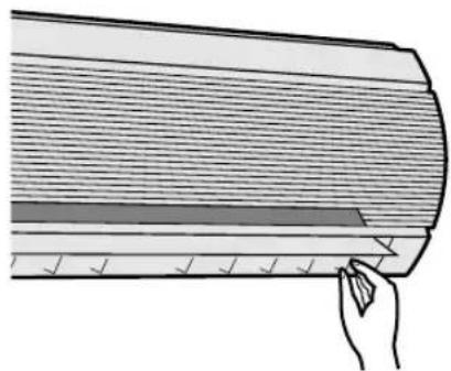
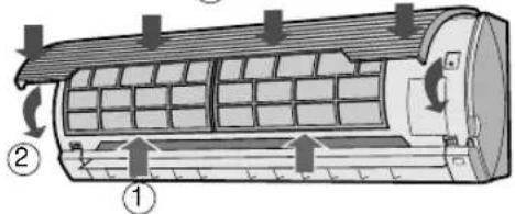
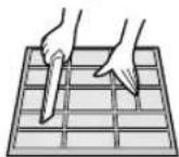
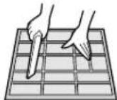
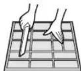
HORIZONTAL AIR FLOW DIRECTION
Hold the horizontal adjustment louvre as shown in the diagram and adjust the air flow direction.
natural_image
Illustration of a hand holding a wooden plank with visible fasteners and a ruler, no text or symbols present
CAUTION
Never attempt to adjust the vertical adjustment louvres manually.
- Manual adjustment of the vertical adjustment louvre can cause the unit to malfunction when the remote control is used for the adjustment.
- When the vertical adjustment louvre is positioned at the lowest position in the COOL or DRY mode for an extended period of time, condensation may result.
Do not adjust the horizontal adjustment louvre extremely to the right or left when operating the air conditioner with fan speed "SOFT" for an extended period of time.
Condensation may form on the louvres.
PLASMACLUSTER OPERATION
Cluster ions and negative ions are released into the room, keeping air in your room clean, and help your physical and mental refreshment.
AIR CLEAN OPERATION : Cluster ions released into air will eliminate airborne mold fungus and deodorize/decompose odor-causing molecules. REFRESHING OPERATION : Negative ions released into the air will help your physical and mental refresh-ment.
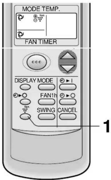
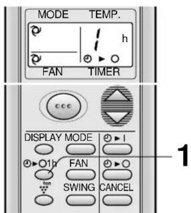
1 During operation, press the PLASMACLUSTER button to select the mode.
AIR CLEAN REFRESHING CANCEL
chemical
Diagram showing ion movement in a membrane with positive and negative ions• In the AIR CLEAN operation, the blue PLASMACLUSTER lamp on the unit will light up.
• In the REFRESHING operation, the green PLASMACLUSTER lamp on the unit will light up.
TO CANCEL
Press the PLASMACLUSTER button until PLASMACLUSTER symbol on the remote control display goes off.
- The PLASMACLUSTER lamp on the unit will turn off.
NOTE:
- Setting of the PLASMACLUSTER operation will be memorized and will operate in the same mode, the next time you turn on the air conditioner.
- To turn off the PLASMACLUSTER Lamp, press the DISPLAY button.
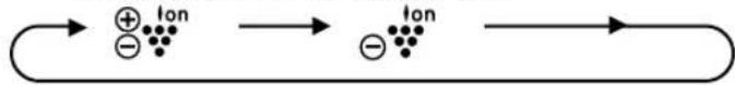
ONE-HOUR OFF TIMER
When the ONE-HOUR OFF TIMER is set, the unit will stop operating after one hour.
1 Press the ONE-HOUR OFF TIMER button.
- The remote control displays " / h Ⓐ▶○".
• The orange TIMER lamp ( ) on the unit will light up.
• The unit will stop operating after one hour.
TO CANCEL
Press the CANCEL button.
- The orange TIMER lamp ( Ⓤ on the unit will turn off.
Or, turn the unit off by pressing the ON/OFF button. - The red OPERATION lamp ( ☐ and the orange TIMER lamp ( ☑ on the unit will turn off.
NOTES:
- The ONE-HOUR OFF TIMER operation has priority over TIMER ON and TIMER OFF operations.
- When the ONE-HOUR OFF TIMER is set while the unit is not operating, the unit will operate for an hour with the formerly set condition.
- If you wish to operate the unit for another hour before the ONE-HOUR OFF TIMER activates, press the ONE-HOUR OFF TIMER button again during operation.
TIMER OFF
The unit will turn off automatically according to your setting.
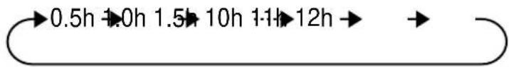
Timer duration can be set from minimum 0.5 hours (30 minutes) to maximum 12 hours.
Up to 9.5 hours, you can set by 0.5 hours (30 minutes) increments and from 10 to 12 hours, by 1 hour increment.
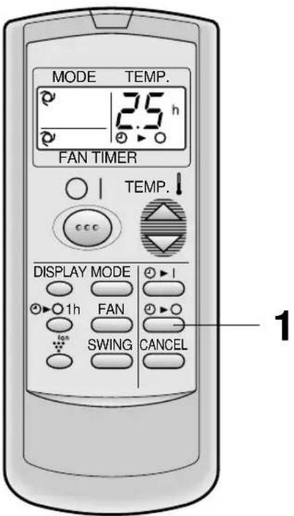
Point the remote control at the signal receiver window on the unit.
1 Press the TIMER OFF ( ⏻ button and set time as desired.
- The time setting will change as you to press the button as follows.
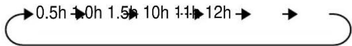
flowchart
graph LR
    A["0.5h"] --> B["1.0h"]
    B --> C["1.5h"]
    C --> D["10h"]
    D --> E["1-1h"]
    E --> F["12h"]
    F --> G["→"]
Hold the button pressed down for fast setting.
- The orange TIMER lamp ( ⏻ on the unit will light.
- The unit will generate a beep when it receives the signal.
- The time setting will count down to show remaining time.
Example : When you wish to stop the operation 2.5 hours later.
When the TIMER OFF is set, the temperature setting is automatically adjusted to prevent the room from becoming excessively hot or too cold while you sleep. (Auto Sleep function)
COOL/DRY MODE:
- One hour after the timer operation begins, the temperature setting rises 1^ higher than the original thermostat setting.
HEAT MODE:
(only for models AY-AP18CE/AY-AP24CE)
- One hour after the timer operation begins, the temperature setting drops 3^ lower than the original thermostat setting.
NOTE:
- The Auto Sleep function will not activate during the FAN ONLY mode.
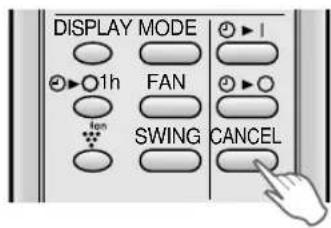
TO CANCEL TIMER
Press the CANCEL button.
• The orange TIMER lamp (☐) on the unit will turn off.
TO CHANGE TIMER SETTING
Press the TIMER button which you wish to change, (TIMER OFF or TIMER ON) and change the time setting.
TIMER ON
The unit will turn on automatically according to your setting.
Timer duration can be set from minimum 0.5 hours (30 minutes) to maximum 12 hours.
Up to 9.5 hours, you can set by 0.5 hours (30 minutes) increments and from 10 to 12 hours, by 1 hour increment.
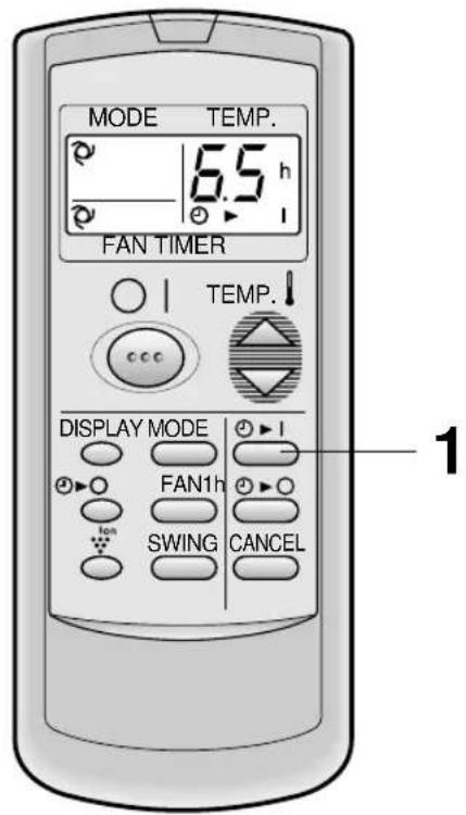
Example : When you wish the room temperature to be as desired 6.5 hours later.
Point the remote control at the signal receiver window on the unit.
1 Press the TIMER ON ( ⏻ button.
- The time setting will change as you press the button as follows.
flowchart
graph LR
    A["0.5h"] --> B["1.0h"]
    B --> C["1.5h"]
    C --> D["10h"]
    D --> E["1-1h"]
    E --> F["12h"]
    F --> G["->"]
Hold the button pressed down for fast setting.
- The orange TIMER lamp ( ☑ on the unit will light.
- The unit will generate a beep when it receives the signal.
- The time setting will count down to show remaining time.
Select the mode, temperature, fan speed setting and PLASMACLUSTER operation as desired.
- When the temperature is set with the TIMER ON, the temperature will show in the display for 5 seconds and then return to the time display.
- If you do not change the setting, the unit will operate with the latest setting.
- The unit will turn on prior to the set time to allow the room to reach the desired temperature by the programmed time. (Awaking function)
NOTES FOR TIMER SETTING AND OPERATION
- The latest time setting will be memorized and will appear on the remote control display the next time you set the TIMER OFF or TIMER ON.
- TIMER OFF and TIMER ON can not be set together.
The latest set TIMER will be active. - When ONE-HOUR OFF TIMER is set, TIMER OFF and TIMER ON will not be available.
- When ONE-HOUR OFF TIMER is set during TIMER OFF or TIMER ON duration, the TIMER ON or TIMER OFF will be cancelled.
AUXILIARY MODE
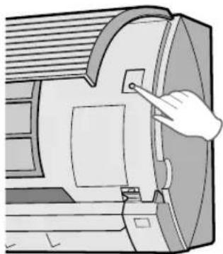
Use this mode when the remote control is not available.
TO TURN ON
Lift the front panel of the indoor unit and press the AUX. button on the operation panel.
- The red OPERATION lamp ( ☐ on the unit will light and the unit will start operating in the AUTO mode.
- The fan speed and temperature setting are set to AUTO.
TO TURN OFF
Press the AUX. button on the operation panel again.
- The red OPERATION lamp ( ☐ on the unit will turn off.
natural_image
Illustration of a hand operating a computer mouse with a button (no text or symbols visible)NOTE:
If the AUX. button is pressed during normal operation, the unit will turn off.
MAINTENANCE
CLEANING THE INTERIOR OF AIR CONDITIONER UNIT
1 Be sure to disconnect the power cord from the wall outlet or turn off the circuit breaker.
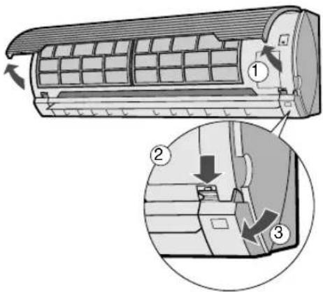
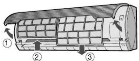
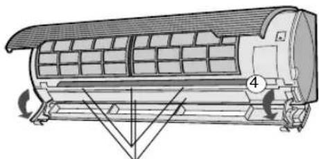
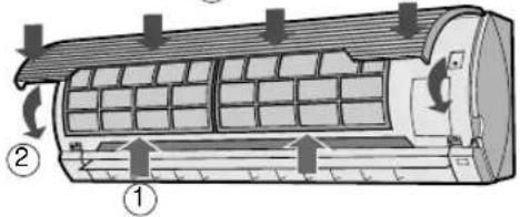
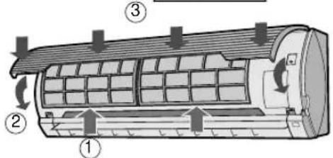
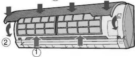
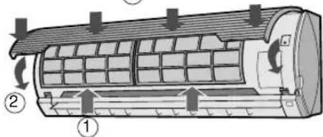
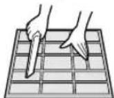
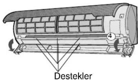
2 OPEN THE LOUVRE UNIT
①Lift the open panel.
②Push down both hooks at the left and right, and release the lock.
③Pull out the louvre unit forward.
④Let it open downward gently.
3 CLEAN THE INTERIOR OF THE AIR CONDITIONER UNIT
Make sure the fan inside is not rotating.
Remove the dust using a vacuum cleaner or wipe with dry cloth.
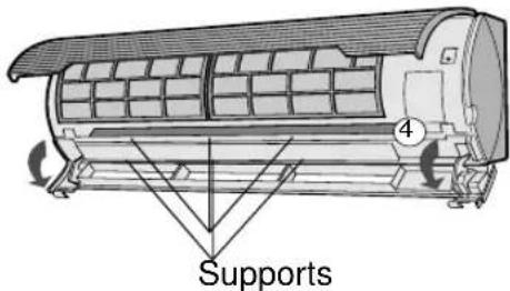
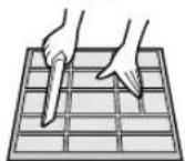
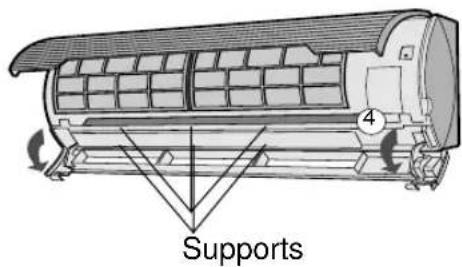
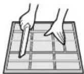
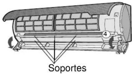
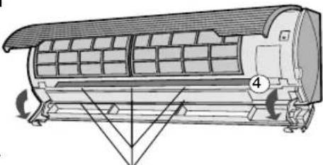
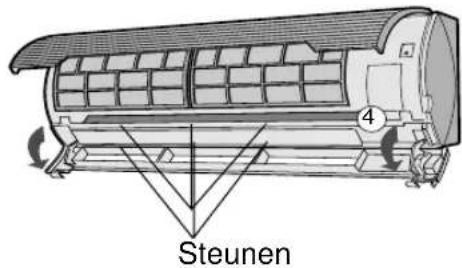
4 CLOSE THE LOUVRE UNIT
1 Lift up the louvre unit and slide it back into its position.
2 Make sure both hooks at the left and right are locked in place and the three supports are firmly fit.
3 Close the open panel.
5 Connect the power cord to the wall outlet or turn on the circuit breaker.
6 Make sure the all lamps on the indicator panel are not blinking.
If the louvre unit is not reinstalled properly, the safety equipment will work and the lamps will blink, preventing the unit from operating. In such case, reinstall the louvre unit properly. Push the ON/OFF button of the remote control and check if the unit operates properly.
MAINTENANCE
Be sure to disconnect the power cord from the wall outlet or turn off the circuit breaker before performing any maintenance.
CLEANING THE FILTERS
The air filters should be cleaned every two weeks.
③
1 TURN OFF THE UNIT
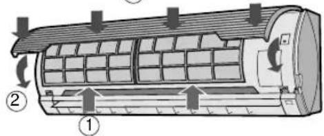
2 REMOVE THE FILTERS
①Lift the open panel.
②Push the air filters up slightly to unlock them.
③Pull the air filters down to remove them.
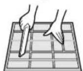
3 CLEAN THE FILTERS
Use a vacuum cleaner to remove dust. If the filters are dirty, wash them with warm water and a mild detergent. Dry filters in the shade before reinstalling.
4 REINSTALL THE FILTERS
①Reinstall the filters in the original positions.
②Close the open panel.
③Push the arrow-marked of the panel firmly to lock it in place.
CLEANING THE UNIT AND THE REMOTE CONTROL
- Wipe them with a soft cloth.
- Do not directly splash or pour water on them. We can cause electrical shock or equipment damage.
- Do not use hot water, thinner, abrasive powders or strong solvents.
MAINTENANCE AFTER AIR CONDITIONER SEASON
1 Operate the unit in the FAN ONLY mode for about half a day to allow the mechanism to thoroughly dry.
2 Stop the operation and unplug the unit. Turn off the circuit breaker, if you have one exclusively for the air conditioner.
3 Clean the filters, then reinstall them.
MAINTENANCE BEFORE AIR CONDITIONER SEASON
1 Make sure that the air filters are not dirty.
2 Make sure that nothing obstructs the air inlet or outlet.
3 Check the outdoor mounting rack periodically for wear and to make sure it is firmly in place.
OPTION KIT
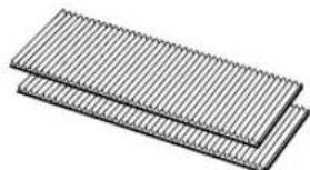
Air Purifying Filter
During operation of the air conditioner, the air purifying filter removes dust and tobacco smoke from the air and discharges clean air.
The apatite antibacterial material used in the air purifying filter suppresses activities of adsorbed viruses and other germs.
The replacement period for the disposable type is approximately 3\~6 months. Contact your dealer for the purchase of this option.
natural_image
Stacked rectangular sheets with parallel grooves, no text or symbols visibleType AZ-F1800C
BEFORE CALLING FOR SERVICE
The following conditions do not denote equipment malfunctions
| UNIT DOES NOT OPERATEThe unit will not operate if it is turned on immediately after it is turned off. The unit will not operate immediately after the mode is changed. This is to protect the internal mechanisms. Wait 3 minutes before operating the unit. | SWISHING NOISEThe soft, swishing noise is the sound of the refrigerant flowing inside the unit. |
| WATER VAPOURIn the COOL and DRY operation, water vapour can sometimes be seen at the air outlet due to the difference between the room air temperature and the air discharged by the unit.In the HEAT operation, water vapour may flow out of the outdoor unit during de-icing. (Only in models AY-AP18CE/AY-AP24CE) | |
| UNIT DOES NOT SEND OUT WARM AIR (Models AY-AP18CE/AY-AP24CE)The unit is preheating or de-icing. | |
| ODORSCarpet and furniture odors that entered into the unit and the air conditioner's inner component odors at the early stage of installation may be sent out from the unit. | ODOR EMITTED FROM THE PLASMACLASTER AIR OUTLETThis is the smell of ozone generated from the ionizer. Density of the ozone is very little, having no adverse effect over your health. The ozone released into the air will decompose soon, and its density in the room will not increase. |
| CRACKING NOISEThe unit may produce a cracking noise. This sound is generated by the friction of the front panel and other components expanding or connecting due to a temperature change. | |
| A LOW BUZZ NOISE EMITTEDThis is a sound emitted when the unit is generating ion clusters. |
If the unit appears to be malfunctioning, check the following points before calling for service.
| IF THE UNIT FAILS TO OPERATE |
| Check to see if the circuit breaker has tripped or the fuse has blown.Check if the louvre unit is properly installed. All lamps on the indicator panel will blink when the louvre unit is not properly installed. |
| IF THE UNIT FAILS TO COOL (OR HEAT) THE ROOM EFFECTIVELY | ||
| Check the filters. If dirty, clean them. | Check the outdoor unit to make sure nothing is blocking the air inlet or outlet. | Check the thermostat is proper setting. |
| Make sure windows and doors are closed tightly. | A large number of people in the room can prevent the unit from achieving the desired temperature. | Check whether any heat-generating appliances are operating in the room. |
| IF THE UNIT FAILS TO RECEIVE THE REMOTE CONTROL SIGNAL | ||
| Check whether the remote control batteries have become old and weak. | Try to send the signal again with the remote control pointed properly towards the unit's signal receiver window. | Check whether the remote control batteries are installed with the polarities properly aligned. |
Please call for service when OPERATION Lamp and TIMER Lamp on the indicator panel blink.

natural_image
Diagram of a remote control device showing battery, switch, and internal components (no text or labels)Batterieabdeckung
HINWEISE:
natural_image
Illustration of a car air conditioner with a handheld device emitting a light beam (no text or symbols)
VORSICHT
chemical
Diagram illustrating the formation of hydrogen peroxide (H2O) from Schimmelpilze Geruch and Ionisator, showing electron transfer and water dissolution steps.natural_image
Illustration of a hand holding a rolled-up document or scroll with a ruler, no text or symbols present
VORSICHT
PLASMACLUSTER-BETRIEB
natural_image
Illustration of a hand pressing a button on a computer monitor (no text or symbols visible)HINWEIS:
natural_image
Technical line drawing of a cylindrical air conditioner unit with cooling fins and ventilation slots (no text or symbols)Stützen
③
1 SCHALTEN SIE DAS GERÄT AUS.
2 ENTNEHMEN SIE DIE FILTER.
natural_image
Stacked rectangular sheets with parallel grooves, no text or symbols visibleTyp AZ-F1800C
BEVOR SIE DEN KUNDENDIENST RUFEN

natural_image
Diagram of a device's internal components with battery and switch assembly (no text or labels)Couvercle des piles
REMARQUES :
natural_image
Illustration of a car air conditioner with a flash unit emitting light (no text or symbols)
ATTENTION
chemical
Chemical reaction diagram showing ionis formation and decomposition of a chondroitin, involving Odeur, désodorise, and H2O.FONCTIONNEMENT DU PURIFICATEUR D'AIR
natural_image
Illustration of a hand holding a rolled-up document or scroll with checkmarks, no text or symbols present
ATTENTION
chemical
Diagram showing ion movement in a membrane with positive and negative ionsnatural_image
Illustration of a hand pressing a button on a computer monitor (no text or symbols visible)REMARQUE :
ETRETIEN
③
1 ETEINDRE L'APPAREIL 2 ENLEVER LES FILTRES
natural_image
Stacked rectangular sheets with parallel grooves, no text or symbols visibleType AZ-F1800C
AVANT D'APPELER LE SERVICE APRES-VENTE

⑱Entrada de aire
natural_image
Diagram of a device with internal components and directional arrows indicating movement (no text or symbols)natural_image
Illustration of a car air conditioner with a flash emitting light (no text or symbols)
PRECAUCIÓN
natural_image
Illustration of a hand touching a curved surface with grid lines (no text or symbols)
PRECAUCIÓN
chemical
Diagram showing Limpiar EL AIRE refresceral cancellation process with ion movement and electron transfernatural_image
Illustration of a hand pressing a button on a computer monitor (no text or symbols visible)NOTA:

1 DESCONECTE LA UNIDAD
2 SAQUE LOS FILTROS
natural_image
Stacked rectangular sheets with parallel grooves, no text or symbols visibleTipo AZ-F1800C
ANTES DE LLAMAR AL DEPARTAMENTO DE SERVICIO TÉCNICO

UNITÀ ESTERNA

natural_image
Illustration of a car air conditioner with a flash emitting light (no text or symbols)
PRECAUZIONI
natural_image
Illustration of a hand holding a rolled-up document or scroll with checkmarks, no text or symbols present
PRECAUZIONI
chemical
Diagram showing ion movement in a membrane with positive and negative ionsnatural_image
Illustration of a hand inserting a component into a machine (no text or symbols visible)PER SPEGNERE

natural_image
Technical line drawing of a cylindrical air conditioner unit with cooling fins and fan blades (no text or symbols)Supporti
MANUTENZIONE
③
1 SPEGNETE L'UNITÀ
2 RIMUOVETE I FILTRI
natural_image
Two stacked rectangular sheets with vertical lines, resembling corrugated metal or composite material (no text or symbols)Tipo AZ-F1800C
PRIMA DI RICHIEDERE ASSISTENZA

natural_image
Diagram of a device with internal components and a close-up view showing internal structure (no text or symbols)Tampa das pilhas
NOTAS:
natural_image
Illustration of a car air conditioner with a handheld flash unit emitting light (no text or symbols)
ATENÇÃO
natural_image
Three rows of circular icons with curved lines, no text or symbols presentFor regulada para manual
natural_image
Three identical panels of a fan-shaped object, each containing six black fan icons, arranged horizontally (no text or symbols)natural_image
Illustration of a hand holding a checkmark on a wooden plank (no text or symbols)
ATENÇÃO
chemical
Diagram showing ion movement in a membrane with positive and negative ionsnatural_image
Illustration of a hand pressing a button on a device component (no text or symbols visible)NOTA:
4 FECHE A UNIDADE DE PERSIANA
1 DESLIGAR A UNIDADE 2 REMOVA OS FILTROS
3 LIMPE OS FILTROS
natural_image
Stack of three parallel corrugated sheets with uniform vertical ridges (no text or symbols)Tipo AZ-F1800C
ANTES DE CHAMAR O SERVIÇO DE ASSISTÊNCIA TÉCNICA

natural_image
Diagram of a remote control device showing internal components and a close-up view of the lid (no text or symbols present)Κάλυμμα μπαταριών
ΣΗΜΕΙΩΣΕΙΣ:
natural_image
Illustration of a car air conditioner with a handheld flash unit emitting light (no text or symbols)
ΠΡΟΣΟΧΗ
chemical
Chemical reaction diagram showing the formation of a broken eggshell from a membrane, with molecular structures and reaction conditions.natural_image
Four circular icons with four blades and one spiral, no text or symbols presentnatural_image
Illustration of a hand holding a rolled-up document or sheet with a ruler, no text or symbols present
ΠΡΟΣΟΧΗ
chemical
Diagram showing ion movement in a membrane with positive and negative ionsnatural_image
Illustration of a hand pressing a button on a mechanical component (no text or symbols visible)ΣΗΜΕΙΩΣΗ:
natural_image
Technical line drawing of an air conditioner unit with cooling fins and fan blades (no text or symbols)Υποστηρίγματα
③
natural_image
Stacked rectangular sheets with parallel grooves, no text or symbols visibleΤγπος AZ-F1800C
WAARSCHUWINGEN BIJ DE PLAATSING / INSTALLATIE
BUITEN-UNIT
①Inlaat (Lucht)
②Opklapbaar paneel
③HELP-toets (AUX.)
④Luchtfilters
⑤Ontvangst-venster
natural_image
Diagram of a device showing internal components with battery and switch, no text or symbols presentBatterijendeksel
OPMERKINGEN:
natural_image
Illustration of a wall-mounted air conditioner with a handheld probe emitting light (no text or symbols)
LET OP
flowchart
graph LR
    A["Start"] --> B["Circular Loop"]
    B --> C["Arrow to Right"]
    C --> D["Arrow to Left"]
    D --> E["Arrow to Right"]
    E --> F["Arrow to Right"]
natural_image
Three rows of circular icons with different leaf-like patterns, no text or symbols presentnatural_image
Illustration of a hand holding a checkmark on a curved surface with horizontal lines (no text or symbols)
LET OP
PLASMACLUSTER BEDIENING
chemical
Diagram showing ion movement in a membrane with positive and negative ionsKOELEN/DROGEN-FUNCTIE:
natural_image
Illustration of a hand pressing a button on a computer monitor (no text or symbols visible)OPMERKING:
ONDERHOUD
③
1 SCHAKEL HET TOESTEL UIT
natural_image
Stacked rectangular sheets with parallel grooves, no text or symbols visibleAZ-F1800C type
VOORDAT U DE STORINGSDIENST BELT
natural_image
Diagram of a device's internal components showing battery, switch, and socket assembly (no text or labels)Pil kapağı
NOTLAR:
natural_image
Illustration of a wall-mounted air conditioner with a handheld flash unit emitting light (no text or symbols)
UYARI
chemical
Diagram illustrating the synthesis of gider, koku, and gider by increasing ionization and water formation in KokuHAVA TEMİZLEME İŞLEMİ
flowchart
graph LR
    A["OTOMATİK DÜŞÜK ORTA"] --> B["Arrow with circular arrow"]
    B --> C["Arrow with triangle"]
    C --> D["Arrow with rectangle"]
    D --> E["YÜKSEK"]
natural_image
Illustration of a hand holding a wooden plank with visible grain and texture (no text or symbols)
UYARI
chemical
Diagram showing ion movement in a membrane with positive and negative ionsBİR SAAT SONRA KAPANMA AYARI
natural_image
Illustration of a hand pressing a button on a computer monitor (no text or symbols visible)NOT:
③

1 ÜNİTEYİ KAPATIN
2 FILTRELERİ ÇIKARIN
natural_image
3D illustration of two stacked rectangular slats with vertical grooves, no text or symbols presentTip AZ-F1800C
SERVİS ÇAĞIRMADAN ÖNCE

- CONTENTS
- PRECAUTIONS
- WARNINGS FOR USE
- WARNINGS FOR INSTALLATION / REMOVAL / REPAIR
- CAUTIONS FOR USE
- CAUTIONS FOR LOCATION / INSTALLATION
- ADDITIONAL NOTES ON OPERATION
- WHEN POWER FAILURE OCCURS
- NOTES FOR MODELS AY-AP18CE/AY-AP24CE
- PREHEATING FUNCTION
- DE-ICING FUNCTION
- HEATING EFFICIENCY
- TIPS ON SAVING ENERGY
- SET THE CORRECT TEMPERATURE
- BLOCK DIRECT SUNLIGHT AND PREVENT DRAFTS
- SET PROPER AIR FLOW DIRECTION TO OBTAIN THE BEST AIR CIRCULATION
- KEEP FILTER CLEAN TO ENSURE THE MOST EFFICIENT OPERATION MAKE MOST OF THE TIMER OFF FUNCTION
- DISCONNECT THE POWER CORD WHEN THE UNIT IS NOT USED FOR AN EXTENDED PERIOD OF TIME
- L.C.D. REMOTE CONTROL DISPLAY
- LOADING BATTERIES Use two size-AAA (R03) batteries.
- NOTES:
- HOW TO USE THE REMOTE CONTROL
- CAUTION
- TIPS ABOUT PLASMACLUSTER OPERATION
- AIR CLEAN OPERATION
- AUTO/DRY MODE
- COOL(HEAT for AY-AP18CE/AY-AP24CE)MODE
- FAN ONLY MODE
- TIPS ABOUT AUTO MODE
- TIPS ABOUT FAN SPEED LAMP
- ADJUSTING THE AIR FLOW DIRECTION
- VERTICAL AIR FLOW DIRECTION
- HOW TO ADJUST THE AIR FLOW DIRECTION
- Adjustment range
- HORIZONTAL AIR FLOW DIRECTION
- PLASMACLUSTER OPERATION
- TO CANCEL
- NOTE:
- ONE-HOUR OFF TIMER
- TIMER OFF
- COOL/DRY MODE:
- HEAT MODE:
- TO CANCEL TIMER
- TO CHANGE TIMER SETTING
- TIMER ON
- Press the TIMER ON ( ⏻ button.
- NOTES FOR TIMER SETTING AND OPERATION
- AUXILIARY MODE
- TO TURN ON
- TO TURN OFF
- MAINTENANCE
- CLEANING THE INTERIOR OF AIR CONDITIONER UNIT
- CLEANING THE FILTERS
- CLEANING THE UNIT AND THE REMOTE CONTROL
- MAINTENANCE AFTER AIR CONDITIONER SEASON
- MAINTENANCE BEFORE AIR CONDITIONER SEASON
- OPTION KIT
- Air Purifying Filter
- BEFORE CALLING FOR SERVICE
- HINWEISE:
- VORSICHT
- PLASMACLUSTER-BETRIEB
- HINWEIS:
- BEVOR SIE DEN KUNDENDIENST RUFEN
- REMARQUES :
- ATTENTION
- FONCTIONNEMENT DU PURIFICATEUR D'AIR
- REMARQUE :
- ETRETIEN
- ETEINDRE L'APPAREIL 2 ENLEVER LES FILTRES
- AVANT D'APPELER LE SERVICE APRES-VENTE
- PRECAUCIÓN
- NOTA:
- DESCONECTE LA UNIDAD
- SAQUE LOS FILTROS
- ANTES DE LLAMAR AL DEPARTAMENTO DE SERVICIO TÉCNICO
- PRECAUZIONI
- PER SPEGNERE
- MANUTENZIONE
- PRIMA DI RICHIEDERE ASSISTENZA
- NOTAS:
- ATENÇÃO
- DESLIGAR A UNIDADE 2 REMOVA OS FILTROS
- LIMPE OS FILTROS
- ANTES DE CHAMAR O SERVIÇO DE ASSISTÊNCIA TÉCNICA
- ΣΗΜΕΙΩΣΕΙΣ:
- ΠΡΟΣΟΧΗ
- ΣΗΜΕΙΩΣΗ:
- WAARSCHUWINGEN BIJ DE PLAATSING / INSTALLATIE
- OPMERKINGEN:
- LET OP
- PLASMACLUSTER BEDIENING
- KOELEN/DROGEN-FUNCTIE:
- OPMERKING:
- ONDERHOUD
- VOORDAT U DE STORINGSDIENST BELT
- NOTLAR:
- UYARI
- HAVA TEMİZLEME İŞLEMİ
- BİR SAAT SONRA KAPANMA AYARI
- NOT:
- SERVİS ÇAĞIRMADAN ÖNCE
Brand : SHARP
Model : AEA18CE
Category : Air-conditioner