
Miros 35 XC4I - Air Conditioning Ariston Thermo - Free user manual and instructions
Find the device manual for free Miros 35 XC4I Ariston Thermo in PDF.

| Product Type | Multi-split wall air conditioner |
| Brand | Ariston Thermo |
| Model | Miros 35 XC4I |
| Nominal cooling power | 5 kW |
| Nominal heating power | 5 kW |
| Power supply | 220-240 V ~ 50 Hz |
| Nominal current | 16 A |
| Residual current protection | 30 mA |
| Refrigerant | R410A |
| Standard refrigerant charge | 1.27 kg |
| Extra charge per meter of pipe | 15 g/m |
| Liquid pipe diameter | 1/4" (6.35 mm) |
| Gas pipe diameter | 3/8" (9.52 mm) |
| Maximum pipe length (standard) | 2 x 7.5 m |
| Maximum pipe length (total/per unit) | 2 x 20 m / 20 m |
| Maximum height difference between units | 15 m |
| Basic functions | Cooling, heating, ventilation, dehumidification, timer |
| Remote control type | Wireless, with batteries supplied |
| Air filter | Washable, periodic cleaning required |
| Condensate drainage | By inclined pipe (3 cm/m), do not submerge in water |
| Installation | Only by qualified professional, comply with applicable standards |
Frequently Asked Questions - Miros 35 XC4I Ariston Thermo
User questions about Miros 35 XC4I Ariston Thermo
0 question about this device. Answer the ones you know or ask your own.
Ask a new question about this device
Download the instructions for your Air Conditioning in PDF format for free! Find your manual Miros 35 XC4I - Ariston Thermo and take your electronic device back in hand. On this page are published all the documents necessary for the use of your device. Miros 35 XC4I by Ariston Thermo.
USER MANUAL Miros 35 XC4I Ariston Thermo
natural_image
Line drawing of a rectangular air conditioner unit with ventilation slots (no text or symbols)
TECNOLOGIA DC
DC TECHNOLOGY

FOLLOW ME
TIMER

SLEEP

ELEVATA
SILENZIOSITÁ
SUPER SILENT

TURBO
CLIMATIZZATORE D'ARIA
AIR CONDITIONER
CLIMATISEUR
CLIMATIZADOR
CONDICIONADOR DE AR
AIRCONDITIONING
DUAL 50 XC4-0
MIROS 25 XC4-I
MIROS 35 XC4-I
ITALIANO....3
ENGLISH 16
FRANÇAIS 29
ESPAÑOLAS 42
PORTUGUÊS 55
NEDERLANDS....68
natural_image
Line drawing of a rectangular air conditioner unit (no text or symbols)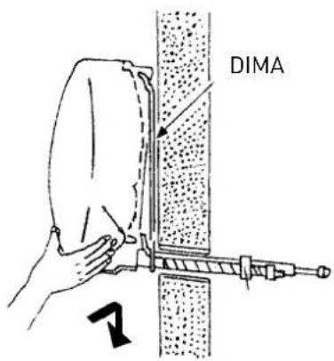

natural_image
Line drawing of a rectangular industrial air conditioner unit with ventilation grilles and control panel (no text or symbols)natural_image
Diagram of a pipe connection with a brick wall and curved pipe, labeled 'si' (no text or symbols beyond label)


natural_image
Technical line drawing of a mechanical component with a screw base and mounting bracket (no text or symbols)2.4 Strumenti
INSTALLATION ACCESSORIES
Wall-hung multi air conditioning units
5 kW
| Name and Description Qty. Operation | ||
Template for the internal unit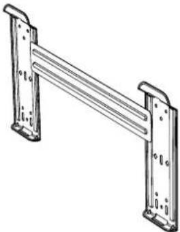 | 1 To install the internal unit | |
Screws + Rawl plugs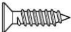 | 6 | |
Condensation discharge pipette with seal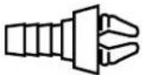 | 1 | To empty the external unit of condensation |
Batteries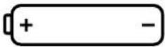 | 2 For the remote control | |
Remote control with support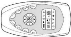 | 1 + 1 | |

CAUTION
READ THIS MANUAL FULLY
AND CAREFULLY BEFORE INSTALLING THE APPLIANCE
Symbol legend:
Failure to comply with this warning implies the risk of injury to persons, which in some circumstances may be fatal. Failure to comply with this warning implies the risk of damage, in some circumstances serious, to properly, plants or animals.
| NORM RISK | ||
| Make sure the installation site and any systems to which the device must be connected comply with the applicable regulations. | Electrocution caused by contact with live wires that have been incorrectly installed. | ⚠️ |
| When drilling the wall, take care not to damage any electrical wiring or existing piping. | Electrocution caused by exposure to live wires. Explosions, fire or intoxication due to gas leaks from damaged pipes. | ⚠️ |
| Protect connection piping and cables so as to prevent damage to them. | Electrocution caused by exposure to live wires. Cold burns due to gas leaking from damaged piping. | ⚠️ |
| Use manual tools and equipment that are suitable for the intended use (in particular, ensure that the tool is not worn and that the handle is intact and securely fi xed); use them correctly and prevent them from falling from a height. Put them safely back in place after use. | Personal injury from the falling splinters or fragments, inhalation of dust, shocks, cuts, pricks and abrasions. | ⚠️ |
| Use electrical equipment suitable for the intended use (in particular, make sure that the power supply cable and plug are intact and that the parts featuring rotary or reciprocating motion are fastened correctly); use this equipment correctly; make sure no equipment could fall from a height. Disconnect it and put it safely back in place after use. | Personal injury from electrocution, fl ying splinters or fragments, inhalation of dust, shocks, cuts, pricks, abrasions, noise and vibration. | ⚠️ |
| Make sure that any portable ladders are securely positioned, that they are strong enough, that the steps are intact and not slippery, that the ladders are not moved with someone on them and that someone supervises at all times. | Personal injury caused by falling from heights or shearing (stepladders shutting accidentally). | ⚠️ |
| Make sure any rolling ladders are positioned securely, that they are suitably resistant, that the steps are intact and not slippery, that the ladders are fitted with handrails on either side of the ladder and parapets on the landing. | Personal injury caused by falling from a height. | ⚠️ |
| During all work carried out off the floor (generally at a height above two metres or 6 feet), make sure that parapets are used to surround the work area or individual harnesses designed to prevent falls, and that the space covered during any accidental fall is free from dangerous obstacles, and that any impact upon falling is cushioned by semi-rigid or deformable surfaces. | Personal injury due to impact, tripping and wounds. | ⚠️ |
| During all work procedures, wear individual protective clothing and equipment. | Personal injury caused by electrocution, fl ying splinters or fragments, inhalation of dust, shocks, cuts, puncture wounds, abrasions, noise and vibration. | ⚠️ |
| All operations on the inside of the appliance must be performed with the necessary caution in order to avoid sudden contact with the sharp parts. | Personal injury from cuts, pricks and abrasions. | ⚠️ |
| Recharge the refrigerant gas in accordance with the instructions provided on the product safety data sheet, wearing protective clothing, avoiding violent outlets of gas from the tank or from the system’s connections. | Personal injury from cold burns. | ⚠️ |
| Do not direct the air flow towards gas hobs or gas stoves. | Explosions, fires or intoxication from the discharge of gas leaking from the burner nozzle once the air flow has put the flame out. | ⚠️ |
| Do not install the external unit in places where it could constitute a risk or an obstruction to the passing of people, or where it could disturb people due to the noise it makes, the heat or air flow. | Personal injury from contusions, stumbling, noise and excessive ventilation. | ⚠️ |
| Do not install the external unit in high positions injuries to things or people | ||
| When lifting loads with a crane or hoist, make sure the equipment used for lifting is stable and efficien and suitably sized for the movement and weight of the load itself; place the load correctly in slings, tie ropes around it to limit any oscillations and lateral movements; lift the load from a position where there is a full view of all the space covered by the load during lifting; do not allow people to pass or stop in the vicinity of the suspended load. | Personal injury from objects falling from a height. Damage to the appliance or surrounding objects due to the appliance falling from a height, knocks. | |
| Do not direct the air flow towards valuable articles, plants or animals. | Damage or perishing due to excessive cold/heat, humidity, ventilation. | |
| Install the device on a solid wall that is not subject to vibrations. Noise during operation. | ||
| Place the condensation drainpipe in such a way as to ensure the correct flow of water towards places where it cannot disturb or damage people, things or animals. | Damage to objects due to dripping water. | |
| When drilling the wall, take care not to damage any electrical wiring or existing piping. | Damage to existing plants. Flooding due to water leaking from damaged pipes. | |
| Perform all electrical connections using suitably-sized conductors. Fire caused by overheating due to electrical current passing through undersized cables. | ||
| Use electrical equipment suitable for the intended use (in particular, make sure that the power supply cable and plug are intact and that the parts featuring rotary or reciprocating motion are fastened correctly); use this equipment correctly; make sure no equipment could fall from a height. Disconnect it and put it safely back in place after use. | Damage to the appliance or surrounding objects from falling splinters, knocks and incisions. | |
| Protect the device and all areas in the vicinity of the work area using suitable material. | Damage to the device or surrounding objects caused by fl ying splinters, knocks and incisions. | |
| Move the appliance with the necessary care. Damage to the device or surrounding objects caused by shocks, knocks, incisions and crushing. | ||
| Organise the dislocation of all debris and equipment in such a way as to make movement easy and safe, avoiding any piles that could yield or collapse. | Damage to the device or surrounding objects caused by shocks, knocks, incisions and crushing. | |
| Reset all safety and control functions affected by any work performed on the device and make sure that they operate correctly before restarting the device. | Damage or shutdown of the device caused by out-of-control operation. | |
| The appliance must be installed in full compliance with national system regulations. | ||
| If the power supply cable is damaged, it must be replaced by the manufacturer or by its technical assistance service, or at least by a suitably qualifi ed individual, in order to prevent all hazards. | ||
| The installation must be carried out by professionally qualifi ed staff, in possession of the skills as required by law | ||
| During the installation process, the refrigerator should be connected fi rst, followed by the electricity supply. In the event of replacement, proceed in the reverse order. | ||
| The air conditioning unit must be earthed completely to avoid electric shocks. Do not connect the earthing line to anti-lightning systems, water or gas pipes, earthing line of the telephone system. | ||
| Do not install the air conditioning unit near heat sources or fl ammable material. | ||
| The air conditioning unit must be earthed completely to avoid electric shocks. Do not connect the earthing line to anti-lightning systems, water or gas pipes, earthing line of the telephone system. | ||
| Do not install the air conditioning unit near heat sources or fl ammable material. | ||
Failure to comply with this warning implies the risk of injury to persons, which in some circumstances may be fatal. Failure to comply with this warning implies the risk of damage, in some circumstances serious, to properly, plants or animals.

1. INSTALLATION
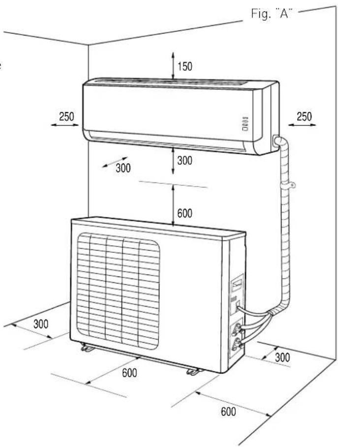
1.1 Minimum distances
To ensure the appliance is installed correctly, keep to the minimum distances indicated in figure "A" and leave enough room for air to circulate freely.
Use the accessories provided with the appliance to carry out the installation properly.
NOTES:
The dimensions of the internal and external units are given at the back of the manual.
WARNING:
- Make sure the installation site and any systems to which the device must be connected comply with the applicable regulations.
- Use manual tools and equipment that are suitable for the intended use.
- When lifting loads with a crane or hoist, make sure the equipment used for lifting is stable and efficient and suitably sized for the movement and weight of the load itself; place the load correctly in slings, tie ropes around it to limit any oscillations and lateral movements; lift the load from a position where there is a full view of all the space covered by the load during lifting; do not allow people to pass or stop in the vicinity of the suspended load.
1.2 Installing the template
NOTES:
Install the internal unit in a place free from all obstacles (such as curtains) that could hinder the receipt of the remote control signals and that allows for the air filters to be pulled out without causing any inconvenience. Install the internal unit in a place where the air flow is not obstructed
WARNING:
Install the template on a solid wall that is not subject to any vibrations.
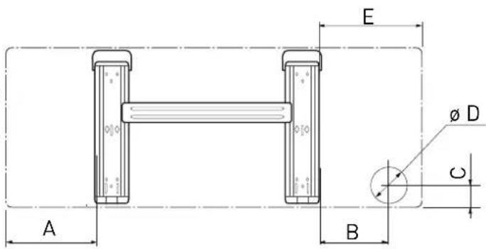
- Using a mason's level, position the template in such a way as to ensure it is perfectly on-axis, both vertically and horizontally.
- Fasten the template with 6 screws. Be careful not to pierce or damage any pipes or wiring in conduits (risk of personal injury from electrocution).
- Then use the other screws to fasten the template to the wall uniformly on all its surface.
- Make a hole in the wall for all piping and electrical connections to pass through.
| A | B | C | D | E | |
| 2,5 kW 13 | 6 41 32,5 | 70 145 | |||
| 3,5 kW 13 | 6 41 32,5 | 70 145 |
1.3 Installing the internal unit
- Push the piping, together with all cables, through the hole made in the wall and hook the internal unit onto the top of the template.
- Shape the piping and cables well.
- Push the lower part of the internal unit well up against the template.
Make sure that:
a. The top and bottom hooks on the internal unit are securely fastened onto the template.
b. The unit is fully horizontal.
If the appliance is not level, water may leak from it onto the floor.
c. The drain pipe is at the right gradient (minimum of 3 cm for each metre in length).
d. The drain pipe stays at the bottom of the hole in the wall.
NOTES:
- Donotkinkorconstrictthepipingoftheinternalunitinanyway. Avoid bends measuring less than 10 cm in radius.
- Do not bend the same section of the pipe too often as it could kink after 3 attempts.
- Remove the closing plugs from the internal unit piping only immediately before you make the connections.
- Keep the condensation drain pipe at the bottom of the hole in the wall, otherwise it could leak.
N.B. Pierce a hole in the wall that is 5-10 mm lower on the outside than it is on the inside so that the slope encourages the downflow of the condensation.
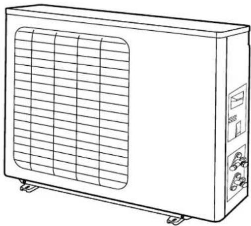
1.4 Installing the external unit
Keep to the procedure described herein, and then start making the connections of the piping and electrical wiring:
- Install the external unit in a place where the noise made by the appliance and the outlet of hot air cannot be a source of inconvenience. Choose a place that does not obstruct the free passage and where the condensation water produced can easily be ducted to the outside.
Do not install the external unit in narrow places which limit the air flow or in places exposed to strong winds.
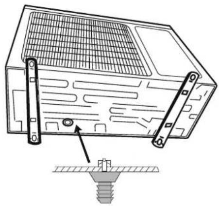
In case of wall installation;
- install the unit securely onto a solid wall.
- pinpoint the most suitable position on the wall, allowing enough room for any maintenance operations to be carried out easily;
- fasten the brackets to the wall using rawlplugs suitable for the type of wall in question (take care not to damage any wiring or piping in conduits);
- use more rawlplugs than the appliance weight would require: during operation, the appliance vibrates and will have to remain installed for years without the screws ever becoming loose.
natural_image
Line drawing of a rectangular air conditioner unit with ventilation slots (no text or symbols)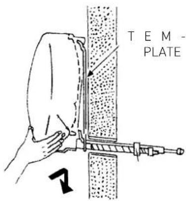
natural_image
Line drawing of a rectangular industrial air conditioner unit with ventilation grilles and control panel (no text or symbols)2. PIPING AND CONNECTIONS
WARNING:
- Do not drink the condensation water (personal injury from poisoning).
- Position the condensation drain pipe in such a way as to allow for the correct downflow of water in dedicated areas, and to prevent any inconvenience or damage to people, things, animals, plants and structures.
- Use manual tools and equipment that are suitable for the intended use.
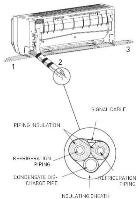
2.1 Connecting the refrigeration piping
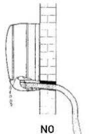
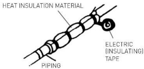
The piping can be positioned in 3 different directions as indicated with numbers 1, 2 and 3 in the adjacent figure. When the pipes are positioned in directions 1 or 3, the special groove designed on the side of the internal unit should be cut using a suitable tool. Turn the pipes in the direction of the hole in the wall (2), taking care not to constrict them in any way, and tape the cooling piping, condensation drain pipe and electrical wiring together with electric (insulating) tape, keeping the condensation drain pipe at the bottom so that the water can flow freely.
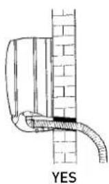
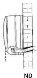
2.2 Draining the condensation from the internal unit
The proper draining of condensation from the internal unit is fundamental for a good installation.
- Keep the condensation drain pipe (ø 18,2 mm) at the bottom of the hole in the wall.
- Make sure the condensation drain pipe has a continuous gradient of approximately 3 cm per metre.
- Do not include any traps in the condensation discharge piping.
- Do not immerse the free end of the condensation drain pipe in water and do not leave it in the vicinity of places emanating unpleasant odours.
- When the installation is complete, before turning on the appliance, make sure the condensation drain pipe works properly by pouring some water into the condensation drip water tray situated inside the internal unit.
2.3 Draining the condensation from the external unit
The condensation or water that forms in the external unit during operation in heating mode can be removed via the drain pipe fi tting. Installation: fasten the drain pipe ( 15 mm) fi tting to hole on the bottom of the unit, as illustrated in the diagram on the right. Connect the condensation drain pipe to the drain pipe fi tting and ensure the other end of the pipe is ducted into a suitable drain.

natural_image
Technical line drawing of a mechanical component with a screw base and mounting bracket (no text or symbols)WARNING:
- Only use specially designed piping for ACR type air conditioning units
- Protect all connection cables and pipes in order to prevent them being damaged.
- Never use pipes that have a thickness which is less than 0.8 mm.
- The appliance must be installed in full compliance with national system regulations.
- During the installation process, the refrigerator should be connected first, followed by the electricity supply. In the event of replacement, proceed in the reverse order.
2.4 Tools
| TOOLS |
| A pressure gauge assembly |
| B pipe cutter |
| C recharge pipe |
| D electronic scale for refrigerant recharge |
| E dynamometric spanner (nominal ø 1/2, 5/8) |
| F clamp-shaped pipe vice |
| G refrigerant cylinder |
| H vacuum pump |
| I leak detector |
A) Pressure gauge assembly
B) Pipe cutter
C) Recharge pipe
The recharge pipe for R410A refrigerant.
D) Electronic scale for refrigerant recharge
Due to its high pressure and speed of evaporation, R410A refrigerant may not be maintained in a liquid state; as a result, refrigerant gas bubbles form inside the cylinder, making it difficult to read the recharge values, and it is therefore recommended that an electronic scale be used to be sure of the values. The electronic scale for the refrigerant recharge consists of a structure with four support points to measure the weight of the refrigerant cylinder. The refrigerant is recharged by opening/closing the valve.
E) Dynamometric spanner
The dynamometric spanner for nominal of 1/2" and 5/8" has a different size on each side to comply with the modified measurements of the pipe unions.
F) Clamp-shaped pipe vice
The pipe vice for R410A is fitted with a clamp which has a receiving opening so that the copper pipe projection may be regulated to 0-0.5 mm, during the processing of the pipe connection.
G) Refrigerant cylinder
H) Vacuum pump
A 1/2 UNF 20 thread/inch and corresponding seal are necessary.
I) Leak detector
For R410A, a special leak detector for HFC refrigerants is used. It must have a high detection sensitivity.
2.5 Thickness of the copper pipes
| NOMINAL DIAMETER(inches) | EXTERNAL DIAMETER(mm) | THICKNESS(mm) |
| 1/4 6,35 0,8 | ||
| 3/8 9,52 0,8 | ||
| 1/2 12,70 0,8 | ||
| 5/8 15,88 1,0 |
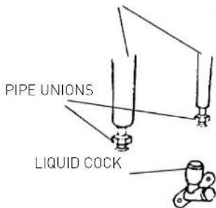
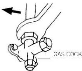
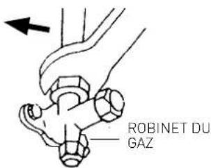
In the split-system type air conditioning units with R410A refrigerant, a three-way valve on the external unit is used, with a pin valve.
2.6 How to connect the pipes
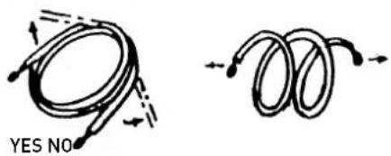
- Remove the closing plugs from the piping only immediately before you make the connection: prevent all dirt and moisture from entering the piping.
- If a pipe is bent too many times, it becomes hard: do not bend the same section more than three times. Unwind the pipe without pulling on it, as illustrated in the figure.
- The insulation around the copper pipes must be at least 6 mm thick.
2.7 Connections to the internal unit
- Shape the connection pipes well following the outline.
- Remove the end cap from the pipes of the internal unit (check that no impurities have been left inside).
- Insert the pipe union and position the flange at the end of the connection pipe, following the instructions in the table (for copper pipes):
| ∅ NOMINAL | ∅ EXTERNAL | mm THICKNESS | MEASUREMENT “A” mm PIPE VICE | CONVENTIONAL PIPE VICE | |
| CLAMP-SHAPED | BUTTERFLY | ||||
| 1/4 6,35 | 0,8 0-0,5 | 1,0-1,5 1,5-2,0 | |||
| 3/8 9,52 | 0,8 0-0,5 | 1,0-1,5 1,5-2,0 | |||
| 1/2 12,70 | 0,8 0-0,5 | 1,0-1,5 2,0-2,5 | |||
| 5/8 15,88 | 0,8 0-0,5 | 1,0-1,5 2,0-2,5 | |||
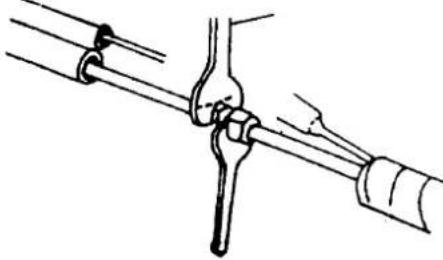
- Connect the pipes using two spanners, taking care not to damage the piping. If the tightening force is insufficient, then there may well be leaks. And if the tightening force is too much, then there may also be leaks as the flange could be damaged. The safest method lies in tightening the connection using a fixed spanner and a dynamometric one: in this case, use the table "tightening torque for flange connections".
- We recommend you leave an extra 50 cm of pipe for any subsequent work carried out in the vicinity of the cocks.
2.8 Connections to the external unit
Screw the pipe unions onto the external unit connections with the same tightness as for the internal unit.
To avoid leaks, pay particular attention to the following points:
- Tighten the pipe unions, taking care not to damage the piping.
- If the tightening force is insufficient, then there may well be leaks. And if the tightening force is too much, then there may also be leaks as the flange could be damaged.
- The safest method lies in tightening the connection using a dynamometric spanner: in this case, use the following tables (for copper pipes)
DYNAMOMETRIC SPANNER
natural_image
Line drawing of a mechanical joint or pipe connection (no text or symbols)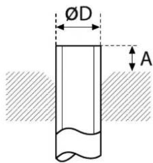
CONNECTION PIPES
TIGHTENING TORQUE FOR THE FLANGE CONNECTIONS
| Pipe Tightening torque[kgf x cm] | Corresponding effort(using a 20 cm spanner) |
| 6.35 mm (1/4") 160 - 200 wrist force | |
| 9.52 mm (3/8") 300 - 350 arm force | |
| 12.70 mm (1/2") 500 - 550 arm force | |
| 15.88 mm (5/8") 630 - 770 arm force |
TIGHTENING TORQUE FOR PROTECTION CAPS
| Tightening torque [kgf x cm] | |
| Service connection 70-90 | |
| Protection caps 250-300 |
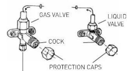
IMPORTANT CHECK FOR ANY REFRIGERANT LEAKS
Once you have made the connections, open the cocks so that the gas fills the piping and always check all piping against leaks using a leak detector (risk of personal injury from cold burns).
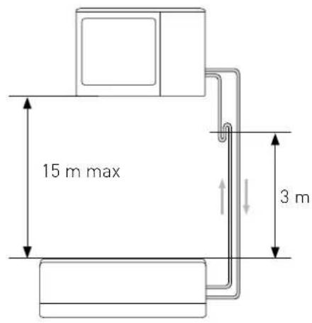
LENGTH OF THE PIPING
The maximum length of the connection piping varies according to the model. When the piping is longer than 7,5 m, pay attention to the quantity of refrigerant that should be added for each metre. Should the external unit have to be installed higher up than the internal unit with a difference in height of more than 3 m, then traps should be fitted on the return piping so that the oil trickling down the pipe walls deposits in the trap until the latter is full. The oil plug that forms will be shot upwards by the gas.
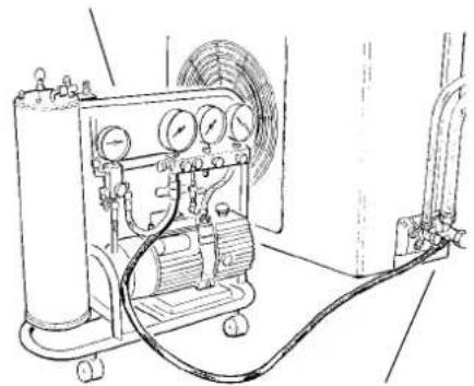
2.9 Making a vacuum and checking the tightness
The air must be expelled from the circuit using a vacuum pump, pump transition fi tting and pressure gauge assembly which are suitable for R410A. Ensure that the vacuum pump is fi lled with oil to the level indicated by the oil gauge and that both cocks on the external unit are shut:
- unscrew the caps on the cocks of the two-way and three-way valves, and on the service valve;
- connect the vacuum pump to the small service valve in the three-way valve of the external unit;
- once you have opened the corresponding valves on the pump, start the latter and leave it to operate. Make a vacuum for approximately 20/25 minutes;
- make sure the pressure gauge shows -0.101 MPa (-760 mmHg);
- shut the cocks on the pump and turn it off. Check that the needle on the pressure gauge does not move for approximately 5 minutes. If the needle moves, this means that air is seeping into the system, and you must check all connections are tight enough and that the piping connections were all made correctly; then repeat the procedure from step 3;
- disconnect the vacuum pump;
- open the cocks on the two-way and three-way valves fully;
- screw the plug tightly to the service outlet ensuring that it is well sealed;
- after having tightened all the plugs, check that there are no gas leaks around their circumference.
WARNING:
Always protect the connection cables and pipes to prevent damage to them, as they could cause gas leaks when damaged (personal injury from cold burns).
VACUUM PUMP
natural_image
Technical line drawing of a mechanical device with gauges, tubing, and housing (no text or symbols)SERVICE CONNECTION
SERVICE CONNECTION
2.10 Refrigerant recovery
Procedure for returning all the refrigerant to the external unit:
- unscrew the caps from the cocks on the two-way and three-way valves.
- set the appliance to cooling mode (check whether the compressor works) and leave the appliance on for a few minutes.
- connect the pressure gauge
- close the two-way valve
- when the pressure gauge reads "0", close the three-way valve and turn the air conditioning off immediately.
- shut the caps on the valves
| MODEL | 5 kW |
| Liquid pipe diameter | 1/4" |
| Gas pipe diameter | 3/8" |
| Maximum length of pipe with standard charge | 2 x 7,5 m |
| Maximum lenght of pipe (total / each unit)* | 2 x 20 m / 20 m |
| Standard charge | 1,27 kg |
| Extra gas recharge | 15 g/m |
| Maximum difference in height between internal and external unit** | 15 m |
| Type of refrigerant | R410A |
(*) at the maximum distance, the efficiency is approximately 90%.
(**) with a difference in height of more than 3 m, we recommend you include a trap as illustrated in the figure.
WARNING:
Recharge any refrigerant gas in accordance with the instructions provided on the product used, wearing protective clothing, avoiding violent outlets of gas from the tank or from the system's connections.
2.11 Charging the refrigerant gas
Before proceeding with the refrigerant charging operations, check that all the valves and cocks are shut.
N.B.: the first time you install the appliance, perform the procedure described in paragraph 2.9 "Making a vacuum and checking the tightness".
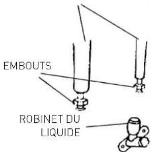
- Connect the service valve to the low pressure connection of the pressure gauge, and connect the refrigerant tank to the central inlet of the pressure gauge. Open the refrigerant tank and then open the cap on the central valve and act on the pin valve until you hear the refrigerant exiting, then release the pin and screw the cap back on.
- Open the three-way valve and the two-way valve;
- Turn on the air conditioning unit on cooling mode. Leave it on for a few minutes;
- Place the refrigerant cylinder above the electronic scale and record the weight;
- Control the pressure shown on the pressure gauge;
- Open the "LOW" knob and allow the refrigerant to flow gradually;
- When the refrigerant recharge introduced into the circuit reaches the set value (provided by the difference in weight of the cylinder), close the "LOW" knob;
- When the charging is complete, test the operation, measuring the temperature of the gas pipe with the special thermometer: the temperature should be between 5^ C and 8^ C more than the temperature read on the evaporation temperature section of the pressure gauge. Now check the stability of the pressure, connecting the pressure gauge assembly to the three-way service valve. Open the two-way and three-way valves fully, turn on the air conditioning unit and check there are no refrigerant leaks using the leak detector. (If there are any leaks, carry out the procedure described in paragraph 2.10 “refrigerant recovery”);
- Disconnect the pressure gauge from the valve and turn the air conditioning unit off;
- Disconnect the tank from the pressure gauge and close all caps.

WARNING:
Do not disperse R410A in the atmosphere: R410A is a greenhouse fluorinated gas, covered by the Kyoto Protocol, with a GWP(*)=1975.
(*) GWP.
stands for «Global Warming Potential».
3. ELECTRICAL CONNECTIONS
WARNING:
- Before carrying out any electrical connection make sure that the units have been disconnected from the electricity supply and that the systems which the appliance must be connected to comply with applicable regulations.
- Only use cables with a suitable section.
- Allow some extra length on the connection cables to allow for future maintenance.
- Never connect the power supply cable by cutting it in half as this could cause a blaze.
- If the power supply cable is damaged, it must be replaced by the manufacturer or by its technical assistance service, or at least by a suitably qualified individual, in order to prevent all hazards
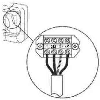
3.1 Internal unit connection
- Remove the terminal board cover.
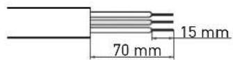
- Feed the internal unit/external unit connection cable from the rear of the internal unit and prepare the tip of the cable.
- Connect the conductors to the screw terminals in accordance with the numbering.
- Use the wire clamp situated underneath the terminal board of the electrical connections.
- Put the cover back in place, ensuring it is positioned correctly. NOTE the connection cables must not pass near electrical boxes, wifi routers or other cables.
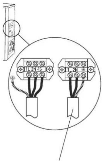
3.2 External unit connection
- Remove the cover.
- Connect the conductors to the screw terminals using the same numbering used in the internal unit. Screw the terminal board screws tightly to avoid any loosening.
- Fasten the cables using the cable clamp.
- Put the cover back in place, ensuring it is positioned correctly.
NOTE: remove the sheath from both ends of the connection wires in the cable as illustrated in the figure. Make sure the connection wires do not come into contact with the piping or other metal parts
Type of electrical connection
| Model Power supply Switch type Connection wire power supply cable | |||
| 5 kW | 220-240V~50Hz 16 A 4G 1,5 mm | ^2 | 3G 1,5 mm ^2 |
NOTE: Electrical connection between the internal and external units must be performed using a H07RN-F cable
3.3 Connection to the electricity mains
The connection of the appliance must comply with European and national regulations and must be protected by a 30 mA differential switch.
Connection to the electricity mains supply must be performed using a fixed connection (not with a mobile plug), equipped with an omnipolar switch complying with all applicable CEI-EN regulations in force (minimum distance between contacts 3mm, switch preferably equipped with fuses).
Proper connection to an efficient earthing system is essential for ensuring the safe operation of the device.
POWER SUPPLY (H07RN-F)
4. FINAL STAGES
WARNING:
- Use manual tools and equipment that are suitable for the intended use.
- Always protect the connection cables and pipes to prevent their being damaged, as they could cause gas leaks when damaged. (Personal injury from cold burns).
-
Recharge the refrigerant gas in accordance with the instructions provided on the product safety data sheet, wearing protective clothing, avoiding violent outlets of gas from the tank or from the system's connections. (Personal injury from cold burns).
-
Wrap some insulating material around the joints of the internal unit and fasten it in place using electric (insulating) tape.
- Fasten the extra part of the signal cable to the piping or to the external unit.
- Fasten the piping to the wall (first cover the pipes with electric insulating tape) using some clips or otherwise insert the pipes in plastic channels.
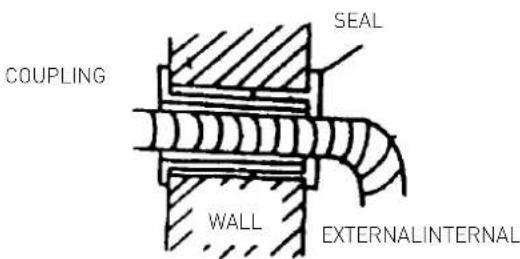
- Seal the hole in the wall through which the piping passes so that no air or water can filter through.
- Outside, insulate all the bare piping, including all valves.
- If the piping has to pass above the ceiling or via a warm damp place, wrap all pipes with some extra insulating material available on sale to prevent condensation from forming.
4.1 Testing
Check the following points:
- INTERNAL UNIT
- Are the ON/OFF and FAN buttons working properly?
- Is the MODE button working properly?
- Are the buttons for the set-point and TIMER working properly?
- Do all the LEDS come on?
- Are the fl aps used to direct the air flow efficien?
6- Is the condensation drained regularly?
- EXTERNAL UNIT
- Is there any noise or vibration during operation?
- Could the noise, air flow or condensation draining disturb the neighbours?
- Are there any refrigerant leaks?
NOTE: The electronic control will only allow the compressor to start three minutes after the unit has been powered.
WARNING:
- Before all interventions, make sure that both units have been disconnected from the electricity supply.
- Make sure the systems to which the appliance should be connected comply with the applicable norms in force.
CHECKS WITHOUT THE USE OF TOOLS OR INSTRUMENTS
Operation in Cooling mode - Visual checks on the Internal Unit
| Problem Check Intervention | ||
| 1 - Frost forms on the Internal Unit's heat exchanger. | 1.A - Frost only on the lower part of the heat exchanger: gas leak.1.B - Frost on the whole heat exchanger: the air fi liter is clogged.The room temperature is low [ < 20°C]. | · Find the leak and recharge.· Clean the air fi liter.Unplug the appliance and switch off the dedicated switch before cleaning. (risk of electrocution).· Check the room temp. |
| 2 - No condensation forms. | 2.A - If the Internal Unit's heat exchanger remains dry and the electricity consumption is much lower than the rated value, then there is a leak. | · Find the leak.· Replace the heat exchanger. |
| 3 - The compressor works but there is little cooling. | 3.A - The External Unit's heat exchanger is clogged or covered: the heat exchange is poor.3.B - The fi ns on the External Unit's heat exchanger are bent. | · Clear the External Unit's heat exchanger.· Straighten the fi ns on the external heat exchanger. |
| 4 - The air temperature is low, but there is little cooling. | 4.A - The Internal Unit fi liter is clogged.4.B - The air recirculates in the Internal Unit.4.C - The appliance is not the right size or there is an overload (e.g. heat sources, overcrowding, etc.). | · Clean the fi liter.· Encourage the free circulation of air.· Replace the appliance or remove the overload. |
| 5 - The compressor stays still. | 5.A - The compressor is very hot: thermal protection. | · Wait for the temperature to drop. |
| 6 - The appliance comes to a stop after a few minutes of operation. | 6.A - The Internal Unit fan is out of order. | · Replace the motor.· Only use original spare parts. |
TROUBLESHOOTING - electrical part
| Problem Check Intervention | ||
| 1 - The appliance gives no sign of life (no LEDs lit, no beeps sounded), not even when you press the ON-OFF button on the internal unit. | 1.A - Check whether there has been a power failure.1.B - Check whether the plug is inserted fully in the socket in the wall.1.C - Check whether the automatic switch has blown.1.D - Check whether the selector has been set to stop. | Restore the power supply and the correct connections.Plug the appliance in fully.Reset the automatic switch.Set the selector to another function. |
| 2 - The remote control does not work or only works at a close distance. | 2.A - Check whether the batteries are low.2.B - Check whether there are any obstacles (curtains or ornaments) between the remote control and the air conditioning unit.2.C - Check whether the distance between the remote control and the unit is too far. | Replace the batteries.Remove all obstacles.Move closer to the air conditioning unit. |
ACCESSOIRES D'INSTALLATION
natural_image
Line drawing of a rectangular air conditioner unit with ventilation slots (no text or symbols)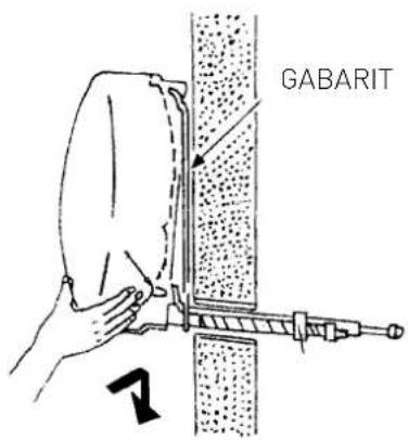

natural_image
Line drawing of a rectangular industrial air conditioner unit with ventilation grilles and control panel (no text or symbols)2. TUYAUTERIES ET RACCORDEMENTS
ATTENTION :
natural_image
Technical line drawing of a mechanical component with a screw base and mounting bracket (no text or symbols)2.4 Instruments
natural_image
Line drawing of a mechanical joint or pipe connection (no text or symbols)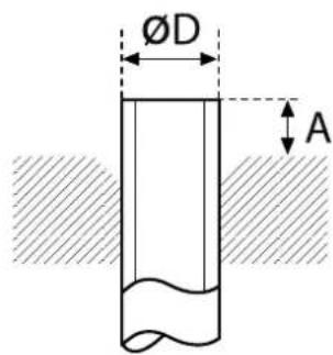
TUYAUX DE RACCORDEMENT
COUPLES DE SERRAGE POUR CONNEXIONS AVEC BRIDE
ALIMENTATION ELÉTRIQUE (H07RN-F)
4. PHASES FINALES
ATTENTION :
natural_image
Line drawing of a rectangular air conditioner unit (no text or symbols)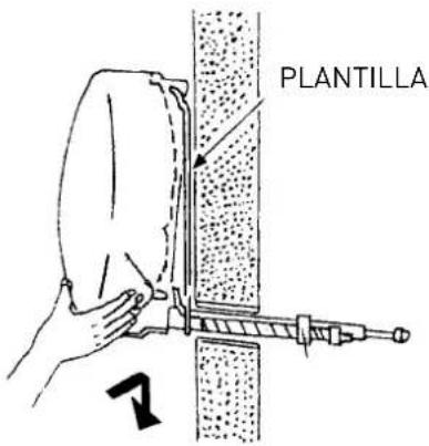

natural_image
Line drawing of a rectangular industrial air conditioner unit with ventilation grilles and control panel (no text or symbols)2. TUBOS Y CONEXIONES
ATENCIÓN:
natural_image
Technical line drawing of a mechanical component with a screw base and mounting bracket (no text or symbols)ATENCIÓN:
natural_image
Line drawing of a rectangular air conditioner unit (no text or symbols)
natural_image
Line drawing of a rectangular industrial air conditioner unit with ventilation grilles and control panel (no text or symbols)2. TUBOS E LIGAÇÕES
ATENÇÃO:
natural_image
Technical line drawing of a mechanical component with a screw base and mounting bracket (no text or symbols)2.4 Instrumentos
4. FASES CONCLUSIVAS
ATENÇÃO:
natural_image
Line drawing of a rectangular air conditioner unit (no text or symbols)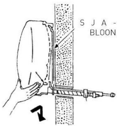
natural_image
Line drawing of a rectangular industrial air conditioner unit with ventilation grilles and control panel (no text or symbols)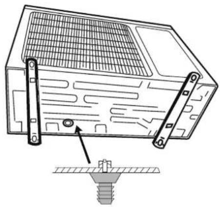
natural_image
Technical line drawing of a mechanical component with a screw base and mounting bracket (no text or symbols)OPGELET:
ELEKTRICITEITSNET (H07RN-F)
4. AFSLUITENDE FASEN
OPGELET:
Internal units that can be connected
In a fl exible system it is possible to connect various types of internal units to a single external unit. The table below lists the possible combinations of types and power of the internal units supported by the fl exible external units, without a reduction in performance. The unit is also able to work with other combinations not listed in the tables, but in these cases the nominal power can not be guaranteed if all the internal units are operating at the same time.
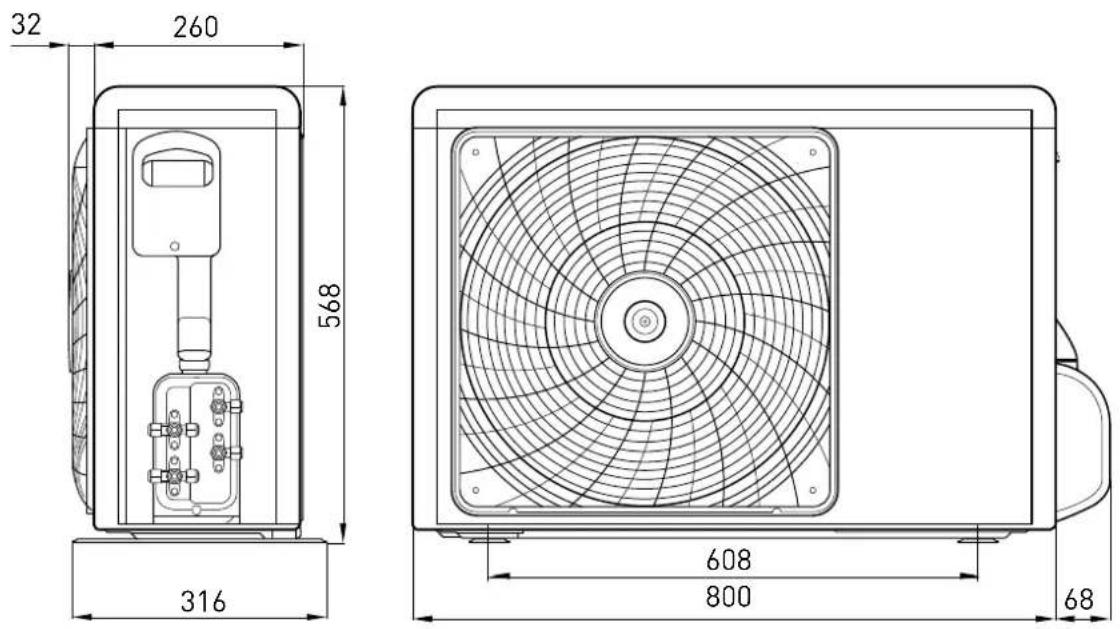
DIMENSIONI/ DIMENSIONS / DIMENSIONS DIMENSIONES / DIMENSÕES/ AFMETINGEN
UNITÁ INTERNA/ INDOOR UNIT/ UNITE INTERNE/ UNIDAD INTERNA/ APARELHO INTERNO/ INTERNE EENHEID
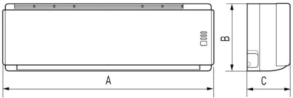
| MOD. A B C | |||
| 2,5 - 3,5 kW | 772 252 192 |
UNITÁ ESTERNA/ OUTDOOR UNIT/ UNITE EXTERNE/ UNIDAD EXTERNA/ APARELHO EXTERNO/ I EXTERNE EENHEID
MOD. 5 kW
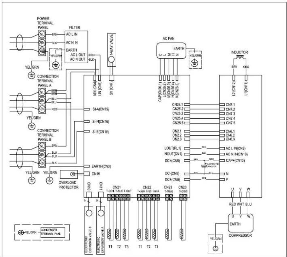
SCHEMI ELETTRICI - WIRING DIAGRAMS - SCHÉMAS ÉLECTRIQUES ESQUEMAS ELÉCTRICOS - ESQUEMAS ELÉCTRICOS - ELEKTRISCHE SCHEMA'S
UNITÁ INTERNA/ INDOOR UNIT/ UNITE INTERNE/
UNIDAD INTERNA/ APARELHO INTERNO/ INTERNE EENHEID
MOD. 2,5 - 3,5 kW

flowchart
graph TD
    subgraph CONTROL UNIT
        A["LOUVER MOTOR"] --> B["CN5"]
        C["DISPLAY UNIT (ROOM TEMP.)"] --> D["CN4"]
        E["TH1"] --> F["CN6 RED"]
        G["TH2"] --> H["CN3 WHT"]
        I["PIPE TEMP."] --> J["CN1"]
        K["FAN MOTOR"] --> L["PG"]
        M["EARTH(CN12)"] --> N["HEATING EXCHANGE"]
        O["SI(CN13)"] --> P["YE/GN RD"]
        Q["CN11"] --> R["BU BN"]
        S["CN16"] --> T["4(SI) 3⊕"]
        U["KN"] --> V["2(N) 1(L)"]
        W["BU(GR)"] --> X["4(SI) 2(N) 1(L)"]
    end
    subgraph Electrical Box
        Y["HEATING EXCHANGE"] --> Z["YE/GN RD"]
        AA["EXCHANGE"] --> AB["YE/GN RD"]
        AC["EXCHANGE"] --> AD["YE/GN RD"]
        AE["EXCHANGE"] --> AF["YE/GN RD"]
    end
    subgraph T.B.
        AG["T.B."] --> AH["T.B."]
    end
    subgraph INDOOR UNIT
        AI["INDOOR UNIT"] --> AJ["OUTDOOR UNIT"]
    end
UNITÁ ESTERNA/ OUTDOOR UNIT/ UNITE EXTERNE/
UNIDAD EXTERNA/ APARELHO EXTERNO/ I EXTERNE EENHEID
MOD. 5 kW
ETICHETTA UNITÁ INTERNA INDOOR UNIT LABEL ETIQUETTE UNITE INTERNE ETIQUETA UNIDAD INTERNA ETIQUETA APARELHO INTERNO INTERNE EENHEID LABEL
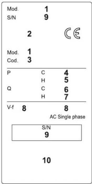
ETICHETTA UNITÁ ESTERNA OUTDOOR UNIT LABEL ETIQUETTE UNITE EXTERNE ETIQUETA UNIDAD EXTERNA ETIQUETA APARELHO EXTERNO EXTERNE EENHEID LABEL
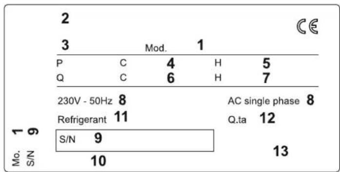
other
| Category | Value | |---|---| | 2 | 3 | | Mod. | 1 | | P | C | | 4 | H | | 5 | Q | | 6 | H | | 7 | AC single phase | | 8 | Refrigerant | | 11 | S/N | | 12 | 9 | | 13 | 10 | CELEGENDA (IT)
- Model - air conditioning unit
- Brand
- Product code
- Rated capacity cooling (W)
- Rated capacity heating (W)
- Rated power absorbed cooling (MAX) (W)
- Rated power absorbed heating (MAX) (W)
- Power supply V voltage frequency (Hz)
- Serial number
- Manufacturer
- Refrigerant gas
- Quantity of refrigerant gas
- IP protection rating
LEGENDA (PT)
ARISTON THERMO GROUP
Ariston Thermo S.p.A.
Viale Aristide Merloni 45
60044 Fabriano (AN)
T: (+39) 0732 6011
Fax: (+39) 0732 602331
www.ariston.com


- CLIMATIZZATORE D'ARIA
- Strumenti
- INSTALLATION ACCESSORIES
- Wall-hung multi air conditioning units
- kW
- CAUTION
- READ THIS MANUAL FULLY
- AND CAREFULLY BEFORE INSTALLING THE APPLIANCE
- INSTALLATION
- Minimum distances
- NOTES:
- WARNING:
- Installing the template
- Installing the internal unit
- Make sure that:
- Installing the external unit
- PIPING AND CONNECTIONS
- Connecting the refrigeration piping
- Draining the condensation from the internal unit
- The proper draining of condensation from the internal unit is fundamental for a good installation.
- Draining the condensation from the external unit
- Tools
- Thickness of the copper pipes
- How to connect the pipes
- Connections to the internal unit
- Connections to the external unit
- IMPORTANT CHECK FOR ANY REFRIGERANT LEAKS
- LENGTH OF THE PIPING
- Making a vacuum and checking the tightness
- Refrigerant recovery
- Charging the refrigerant gas
- ELECTRICAL CONNECTIONS
- Internal unit connection
- External unit connection
- Connection to the electricity mains
- FINAL STAGES
- Testing
- - INTERNAL UNIT
- - EXTERNAL UNIT
- CHECKS WITHOUT THE USE OF TOOLS OR INSTRUMENTS
- TROUBLESHOOTING - electrical part
- ACCESSOIRES D'INSTALLATION
- TUYAUTERIES ET RACCORDEMENTS
- ATTENTION :
- Instruments
- PHASES FINALES
- TUBOS Y CONEXIONES
- ATENCIÓN:
- TUBOS E LIGAÇÕES
- ATENÇÃO:
- Instrumentos
- FASES CONCLUSIVAS
- OPGELET:
- AFSLUITENDE FASEN
- Internal units that can be connected
- DIMENSIONI/ DIMENSIONS / DIMENSIONS DIMENSIONES / DIMENSÕES/ AFMETINGEN
- SCHEMI ELETTRICI - WIRING DIAGRAMS - SCHÉMAS ÉLECTRIQUES ESQUEMAS ELÉCTRICOS - ESQUEMAS ELÉCTRICOS - ELEKTRISCHE SCHEMA'S
- LEGENDA (IT)
- LEGENDA (PT)
Brand : Ariston Thermo
Model : Miros 35 XC4I
Category : Air Conditioning