
DI Solo - Basket V-ZUG - Free user manual and instructions
Find the device manual for free DI Solo V-ZUG in PDF.
| Product type | Range hood |
| Brand | V-ZUG |
| Model | DI Solo |
| Use | Above a cooktop for domestic use |
| Power supply | 220–240 V, 50–60 Hz, max. 460 W (option 300 W) |
| Lighting | Halogen lamp 12 V, 35 W, socket MR16 |
| Motor power levels | 4 levels + intensive level (auto return to level 3 after 3 min) |
| Timer | Delayed shut-off: activation by 5 presses to the left, switches from level 3 to level 1, then stops after about 15 min |
| Metal filter | 3-D filter with bayonet mount, dishwasher safe (max 65 °C) or hand wash |
| Charcoal filter | Optional for recirculation mode, replace every 3 to 6 months |
| Filter cleaning indicator | Flashing red light after 15 hours of service; reset by pressing left for 5 seconds |
| Materials | Glass and stainless steel |
| Control | Sliding control (left/right) |
| Indicator lights | LEDs on the chimney indicating hood status |
| Surface cleaning | Dish soap or suitable all-purpose cleaner; do not use steam or high-pressure cleaner |
| Lamp replacement | Disconnect the appliance, lift the retaining ring with a screwdriver, disconnect the plug |
| Safety | Never use without grease filter; do not flambé under the hood; fire risk if filters are greasy |
| Repairability | Original parts only; intervention by qualified personnel |
| Exhaust mode | Exhaust or recirculation (with charcoal filter) |
| Standards | WEEE Directive 2002/96/EG |
Frequently Asked Questions - DI Solo V-ZUG
User questions about DI Solo V-ZUG
0 question about this device. Answer the ones you know or ask your own.
Ask a new question about this device
Download the instructions for your Basket in PDF format for free! Find your manual DI Solo - V-ZUG and take your electronic device back in hand. On this page are published all the documents necessary for the use of your device. DI Solo by V-ZUG.
USER MANUAL DI Solo V-ZUG
natural_image
Technical line drawing of a cylindrical component mounted on a flat base plate (no text or symbols)Solo
de
Liebe V-ZUG-Kundin, lieber V-ZUG-Kunde
natural_image
Diagram of a mechanical device with a cylindrical component and rotating components, showing motion arrows (no text or symbols)de
Beleuchtungswechsel
Störungen
natural_image
Diagram of a mechanical assembly with a cylindrical component and a rotating base, showing motion arrows (no text or symbols)Anomalies :
natural_image
Diagram of a mechanical assembly with a cylindrical component and a rotating base, showing motion arrows (no text or symbols)it
This instruction manual contains important and helpful hints which must be followed for a safe and troublefree operation of the extractor hood. Please keep the operating and assembly instructions in a safe place for reconsultation.
Designated use
The extractor hood should be used solely for removing moisture and cooking odours in the kitchen. Any other usage is considered to be improper. An improper usage of the extractor can endanger persons and items. The extractor hood should not be used as a clipboard for subjects like for example bottles or spice cans.
Installation
The appliance should be connected only by an authorized expert according to all relevant regulations of the electricity supply enterprises as well as the building regulations of the countries. Please pay attention to the assembly instructions!
Damaged units should not be used. Faulty parts should be replaced by original ones. Repairs should be carried out only by authorized technical staff.
Risk of poisoning!
If the extractor hood with an integrated supercharger for exhaust air management (version B) is operated at the same time with other heatproducing appliances dependent on air room (e.g. run by wood, gas, oil or coal) deadly combustion gases can be led back into the room by an accruing under pressure. Therefore please make sure that at any time a sufficient supply air flow is provided. The low pressure in the room should not be greater than 4 Pa (0.04mbar).
Risk of fire!
The extractor hood should never be used without a fat filter and should be operated under ward. Overfated filters signify fire risk! Deepfry under the extractor hood only under constant ward! Please make sure that the filters are cleaned regularly. „Flambé” under the extractor hood is not permitted! Gas devices may be used under the extractor hood only with pots on! Please run the extractor hood on level 2 or higher if you use more than 3 gas cookeries at the same time. Thereby a heat accumulation in the appliance is avoided.
Risk of electric shock!
Please do not clean the extractor hood with a steam cleaner or high water pressure. Please separate the extractor hood from the power supply network and pay attention to the fact that no water seeps into the appliance during the cleaning process.
CAUTION: Accessible parts may become hot when used with cooking appliances.
Subject to technical modifications!
General functionality:
The extractor hood has been developed especially for the extraction of cooking vapours for use in the private home. The arised cooking vapours are caught by the extractor hood and absorbed by the metal grease filters.
The metal filter has a 3D structure which allows a suction of the cooking odours from three sides: from below, sideways as well as from above.
The metal grease filter is equipped with a bayonet joint so that it can be easily taken out for cleaning. The lighting is arranged in form of a halogen lighting concentric in the filter and illuminates the cooking zone centrally.
The extractor hood is produced of noble materials like stainless steel, aluminium or glass.
The power of extraction and the lighting are operated by a switch lever. Lightemitting diodes in the chimney provide information about the operating condition of the extractor hood.
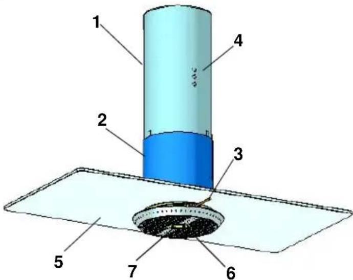
1 Upper chimney
2 Lower chimney
3 Switch lever
4 Light-emitting diode (LED)
5 Safety glass pane
6 Metal grease filter
7 Halogen lighting
Product description
Operating
The extractor hood is operated by a switch lever which can be moved to the left and to the right.
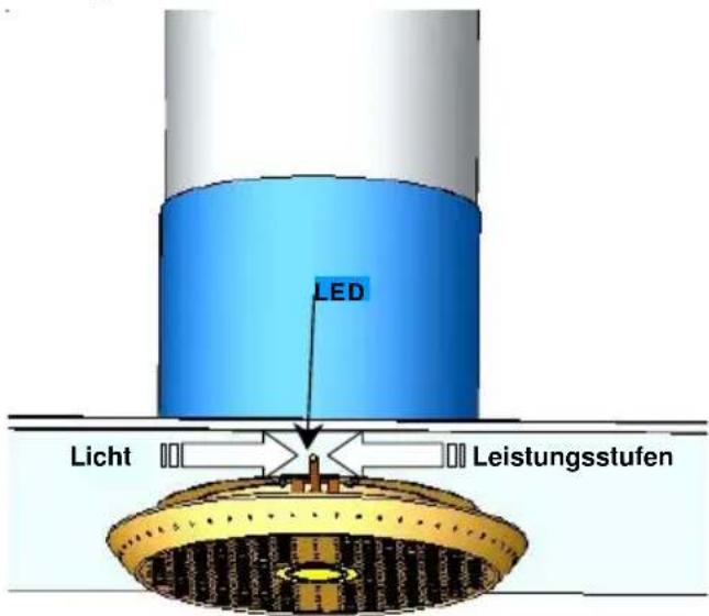
Power of the supercharger
The power of the supercharger is operated by pushing the switch lever to the left. The individual levels have to be switched step-by-step. Four different performance levels can be selected. In order to switch off the extractor please push the switch lever to the left as long as all lightemitting diodes have gone out. In order to switch off the supercharger from every step press the stick as long to the left, until all LED's have gone out.
Level 1 = low performance of the supercharger push to the left one time
Level 2 = middle performance of the supercharger push to the left two times
Level 3 = high performance of the supercharger push to the left three times
Level 4 = intensive level
(supercharger switches back after 3 min. to level 3)
push to the left four times
Automatic follow up
Press the rod to the left 5 times to activate the automatic after-run; 3 LEDs in the upper tower light up green and the lamp in the rod flashes. The extractor hood switches back from level 3 to level 1 and runs for approx. \~15 min. there before switching off.
Switching on the lighting
Please push the switch lever to the right for switching the light on and off.
Display cleaning of the filter
Please clean the filter after 15 operating hours of the extractor hood. At that time the red lightemitting diode in the upper chimney section is flashing. Please keep the switch lever pushed left for 5 sec. after the cleaning. This resets the counter and the red light-emitting diode goes out.
Cleaning and care
Cleaning of the surface
Risk of electric shock! Please separate the extractor hood from the power supply network by pulling the plug or the disconnection of the fuse. Please pay attention to the fact that no water seeps into the appliance during the cleaning process.
Untimely cleaning of the surface saves later a troublesome removing of stubborn soiling. For the cleaning use only commercial detergent or allpurpose cleaners which are suitable for stainless steel / aluminium. Please do not use scouring agents or steel wool! After the cleaning of the extractor hood please tend the stainless steel surfaces with a highgrade steelcare product.
Varnished surfaces have to be cleaned only with a light soapy water and a very soft cloth.
Please clean all glasssurfaces with a customary glass cleaning agent and with a soft cloth.
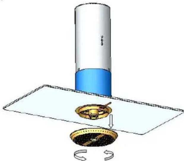
Exchange and cleaning of the metal grease filter
Fire risk! The performance of the extractor hood is affected by containing fat remains and therefore the fire risk increases. To prevent a fire risk please clean the metal filter regularly (see display “filter cleaning”). The metal grease filter must be cleaned every 2 weeks at the latest.
For the removal of the metal grease filter please unscrew it in anticlockwise direction. The metal filter can be taken out (top down).
The metal grease filter is to be cleaned at best in a dishwasher or in hot soapy water. Aggressive cleaners should not be used.
The guarantee can not be applied if a discolouring on the metal grease filter is a result of using an aggressive dishwashing liquid. Please avoid temperatures over 65 degrees.
Attention: do not use 3-phase-cleaners or clean the filter in a commercial dishwasher. The use of aggressive cleaners like fuel, acetone, trichlorethylene destroys the filter! After the cleaning please reinstall the filter by screwing it on in clockwise direction.
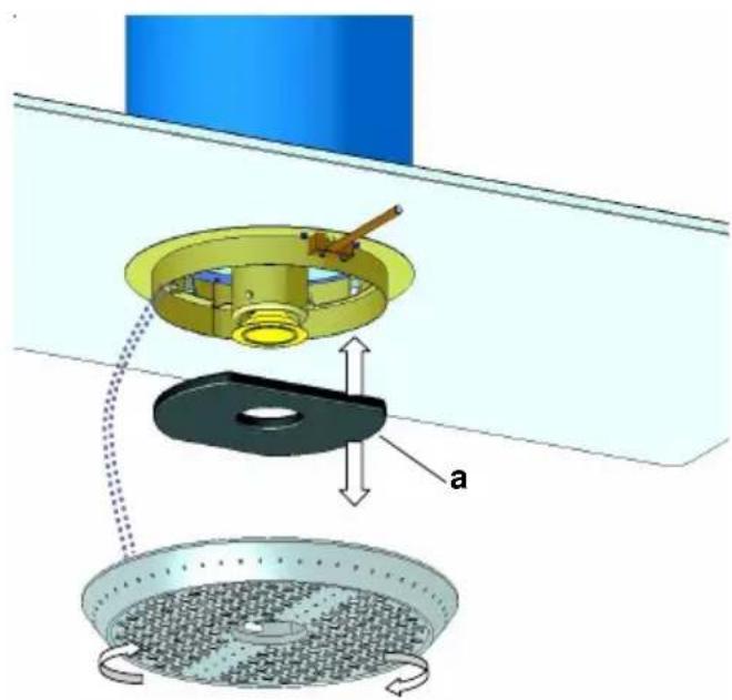
Exchange of the active carbon filter
(only extractor hoods with circular air – version D)
Active carbon filters (a) bundle up odorous substances which are contained in the
natural_image
Diagram of a mechanical assembly with a cylindrical component and a rotating base, showing motion arrows (no text or symbols)kitchen fume. According to the strain of work this filter has to be exchanged after 3-6 months.
The charcoal filter can be exchanged right after taking off the metal filter (see also cleaning of the metal grease filter).
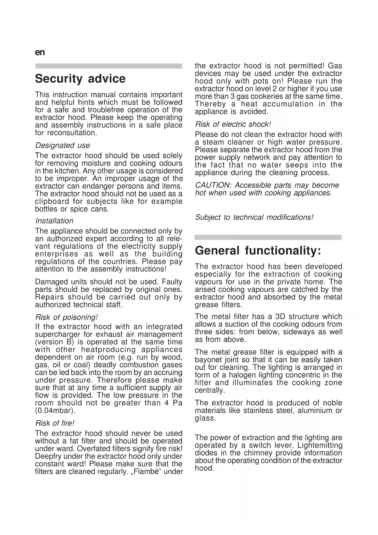
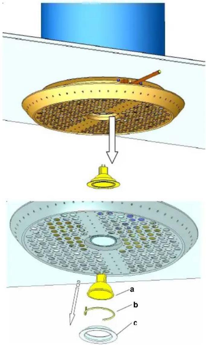
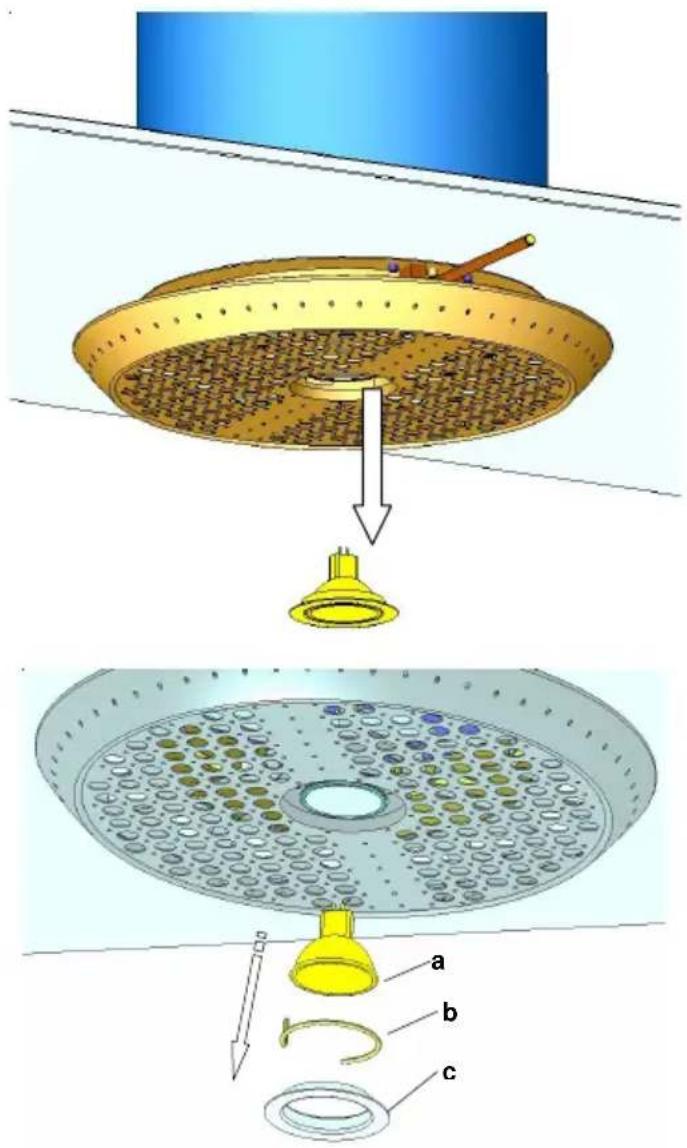
Exchange of the lighting
Please cut the connection between the extractor hood and the power supply system!
The lighting remains hot for some time. Please wait therefore for some time till the lighting has cooled off.
For the exchange of the lighting at first please take the retaining ring (c) out of the extractor hood with a screwdriver. Afterwards solve the plug of the light bulb (a) and separate it from the fixture. Therefore the feather ring (b) must be crushed and be removed upwards. The installation of the new lighting is made in reverse order.
Dysfunctions
Please refer to our customer service if
- the extractor hood produces too much undefined noise and the control of the exhaust air path reveals no faults;
- the supercharger works faulty;
- the circuit operates invalid.
Please indicate your type of extractor hood and the serial number. These informations are mentioned on the type sheet which is situated inside the hood on the filter.
Disposal
Packaging
The packaging of the appliance is recyclable. It is made up off cardboard and polyethylene foil (PE). Please dispose these materials in a environmentally aware, responsible way and in accordance with the regulations of your local authority.
Extractor hood
Your local community will be able to advise you on an environmentally compatible disposal of sorted out household appliances.
Environmental Information
This appliance is labelled in accordance with European Directive 2002/96/EG concerning used electrical and electronic appliances (waste electrical and electronic equipment - WEEE). The guideline determines the framework for the return and recycling of used appliances as applicable throughout the EU. Please ask your dealer about current means of disposal.
Technical data
Connection mains:
220 240V / 50 -60Hz, max. 460W, Option 300W
Lighting: Halogen cold light 12V 35Watt
Sockel MR16
natural_image
Diagram of a mechanical assembly with a cylindrical component and a rotating disc (no text or symbols)Cambio de bombillas
Problemas
natural_image
Diagram of a mechanical assembly with a cylindrical component and a rotating base, showing motion direction (no text or symbols)natural_image
Diagram of a ceiling-mounted fan or fixture with a yellow base and a blue top, showing internal components and airflow direction (no text or symbols)Storingen.
natural_image
Diagram illustrating a mechanical assembly with a blue cylinder, a rotating component, and a rotating base with directional arrows (no text or symbols)Замена фильтра с
pyc
Limpar as superfícies
natural_image
Diagram of a mechanical device with a cylindrical component and rotating base, showing motion arrows (no text or symbols)sv
Bästa kund,
1 Övre trumma
2 Nedre trumma
3 Manövreringsspak
4 Effektindikator (LED)
5 Säkerhetsglasskiva
6 Metallfilter
7 Halogenbelysning
Handhavande
natural_image
Diagram of a mechanical assembly with a cylindrical component and a rotating base, showing motion arrows (no text or symbols)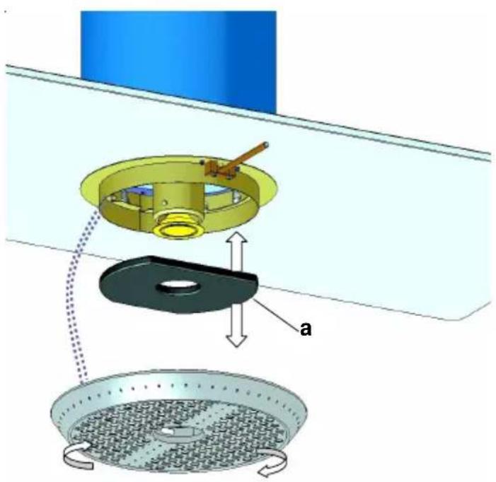
Byta lampa
Störningar
Fare for forgiftning!
1 Topptårn
2 Undertårn
3 Stavbetjening
4 Effektdisplay (LED)
5 Sikkerhetsglassrute
6 Metallfilter
7 Halogenlys
Betjening
Byte Iys
Feil

- de
- Beleuchtungswechsel
- Störungen
- Anomalies :
- Designated use
- Installation
- Risk of poisoning!
- Risk of fire!
- Risk of electric shock!
- General functionality:
- Product description
- Operating
- Power of the supercharger
- Automatic follow up
- Switching on the lighting
- Display cleaning of the filter
- Cleaning and care
- Cleaning of the surface
- Exchange and cleaning of the metal grease filter
- Exchange of the active carbon filter
- Exchange of the lighting
- Dysfunctions
- Disposal
- Packaging
- Extractor hood
- Environmental Information
- Technical data
- Cambio de bombillas
- Problemas
- Storingen.
- Замена фильтра с
- pyc
- Limpar as superfícies
- sv
- Handhavande
- Byta lampa
- Störningar
- Fare for forgiftning!
- Betjening
- Byte Iys
- Feil
Brand : V-ZUG
Model : DI Solo
Category : Basket