
RHV9102 - Basket ROSIERES - Free user manual and instructions
Find the device manual for free RHV9102 ROSIERES in PDF.
| Brand | Rosieres |
| Model | RHV9102 |
| Product type | Kitchen hood |
| Installation | Extraction or recirculation version (charcoal filter not supplied) |
| Dimensions (approx.) | Width 90 cm, depth 50 cm, variable height with telescopic chimney |
| Weight (approx.) | 15 kg |
| Power supply | 230 V ~ 50 Hz |
| Motor power (approx.) | 250 W |
| Lighting | Halogen bulbs (2 x 20 W) |
| Number of speeds | 4 speeds + 2 intensive (depending on controls) |
| Controls | Touch with display or buttons (depending on version) |
| Gas sensor | Yes (on some models), adjustable sensitivity |
| Grease filters | Metallic, dishwasher safe |
| Charcoal filter | Optional, to be replaced periodically |
| Maintenance alarm | 30 h for grease filters, 120 h for charcoal |
| Minimum distance from cooking surface | 350 mm |
| Exhaust duct diameter | 150 mm (recommended) |
| Included accessories | Wall bracket, plugs, screws, reduction ring (recirculation) |
| Manual pages | 28 pages (FR) |
Frequently Asked Questions - RHV9102 ROSIERES
User questions about RHV9102 ROSIERES
0 question about this device. Answer the ones you know or ask your own.
Ask a new question about this device
Download the instructions for your Basket in PDF format for free! Find your manual RHV9102 - ROSIERES and take your electronic device back in hand. On this page are published all the documents necessary for the use of your device. RHV9102 by ROSIERES.
USER MANUAL RHV9102 ROSIERES
INSTRUCTIONS FOR INSTALLATION AND USE
The hood may be in the filtering or the ducting version.
Filtering version (Fig. 1): The hood aspirates the kitchen air saturated with fumes and odours, purifies it through the grease filters and charcoal filters and returns clean air into the room. For constant efficiency, the charcoal filters must be replaced periodically. The charcoal filters are not supplied.
Ducting version (Fig. 2): The hood aspirates the kitchen air saturated with fumes and odours, passes it through the grease filters and expels it to the outside through an outlet pipe. With this version the charcoal filters are not required. Decide from the outset on the type of installation (filtering or ducting). For greater efficiency, we recommend you install the hood in the ducting version (if possible).
INSTALLATION
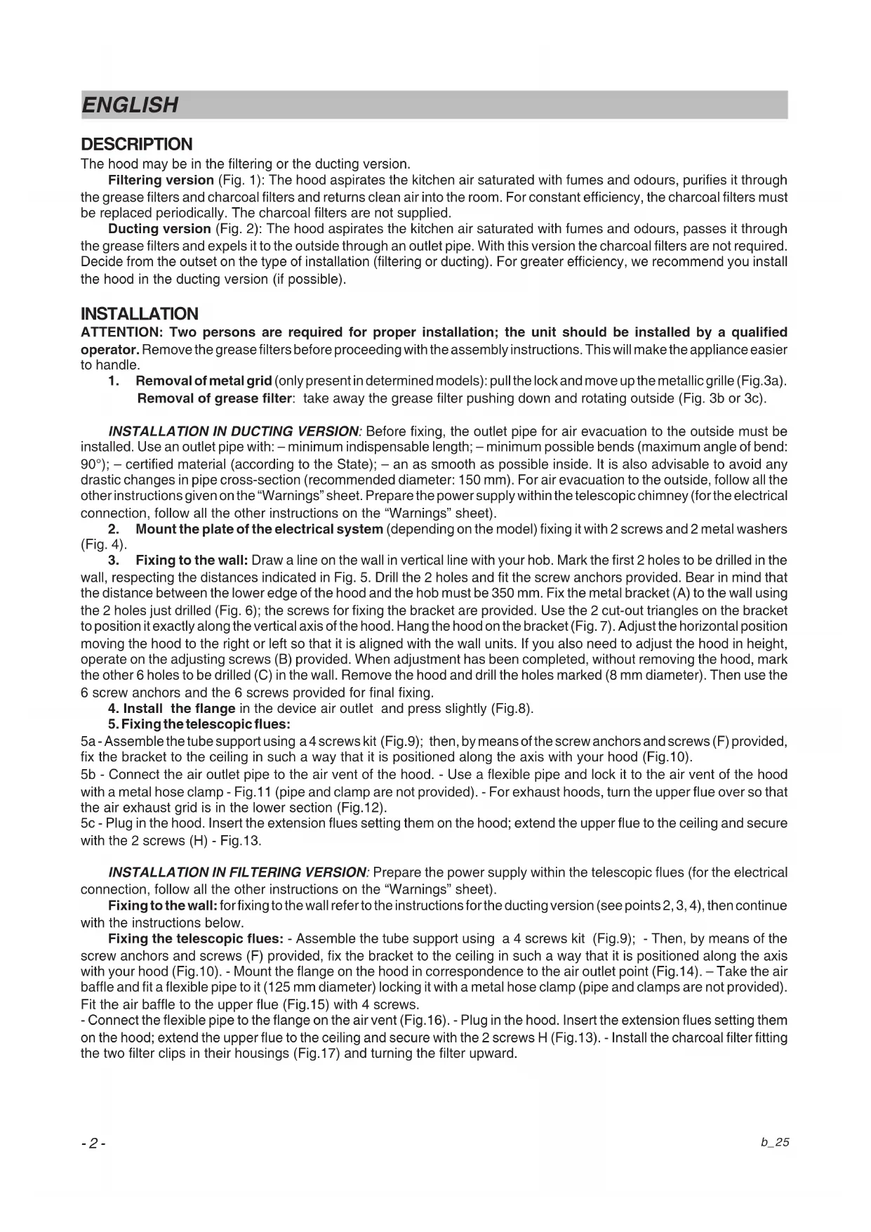
ATTENTION: Two persons are required for proper installation; the unit should be installed by a qualified operator. Remove the grease filters before proceeding with the assembly instructions. This will make the appliance easier to handle.
- Removal of metal grid (only present in determined models): pull the lock and move up the metallic grille (Fig.3a).
Removal of grease filter: take away the grease filter pushing down and rotating outside (Fig. 3b or 3c).
INSTALLATION IN DUCTING VERSION: Before fixing, the outlet pipe for air evacuation to the outside must be installed. Use an outlet pipe with: – minimum indispensable length; – minimum possible bends (maximum angle of bend: 90^ ); – certified material (according to the State); – an as smooth as possible inside. It is also advisable to avoid any drastic changes in pipe cross-section (recommended diameter: 150 mm). For air evacuation to the outside, follow all the other instructions given on the “Warnings” sheet. Prepare the power supply within the telescopic chimney (for the electrical connection, follow all the other instructions on the “Warnings” sheet).
-
Mount the plate of the electrical system (depending on the model) fixing it with 2 screws and 2 metal washers (Fig. 4).
-
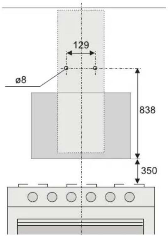
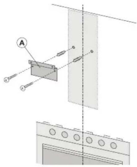
Fixing to the wall: Draw a line on the wall in vertical line with your hob. Mark the first 2 holes to be drilled in the wall, respecting the distances indicated in Fig. 5. Drill the 2 holes and fit the screw anchors provided. Bear in mind that the distance between the lower edge of the hood and the hob must be 350 mm. Fix the metal bracket (A) to the wall using the 2 holes just drilled (Fig. 6); the screws for fixing the bracket are provided. Use the 2 cut-out triangles on the bracket to position it exactly along the vertical axis of the hood. Hang the hood on the bracket (Fig. 7). Adjust the horizontal position moving the hood to the right or left so that it is aligned with the wall units. If you also need to adjust the hood in height, operate on the adjusting screws (B) provided. When adjustment has been completed, without removing the hood, mark the other 6 holes to be drilled (C) in the wall. Remove the hood and drill the holes marked (8 mm diameter). Then use the 6 screw anchors and the 6 screws provided for final fixing.
-
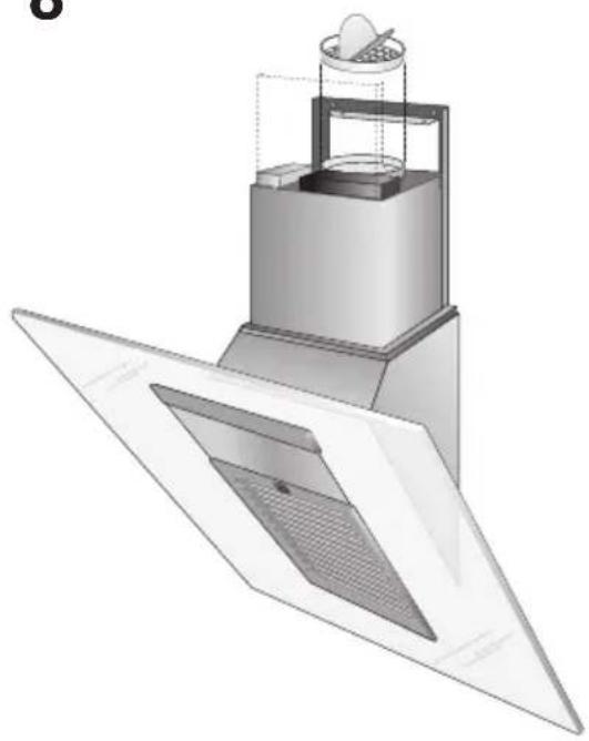
Install the flange in the device air outlet and press slightly (Fig.8).
-
Fixing the telescopic flues:
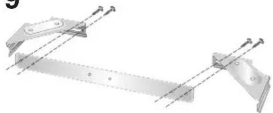
5a - Assemble the tube support using a 4 screws kit (Fig.9); then, by means of the screw anchors and screws (F) provided, fix the bracket to the ceiling in such a way that it is positioned along the axis with your hood (Fig.10).
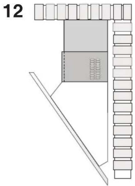
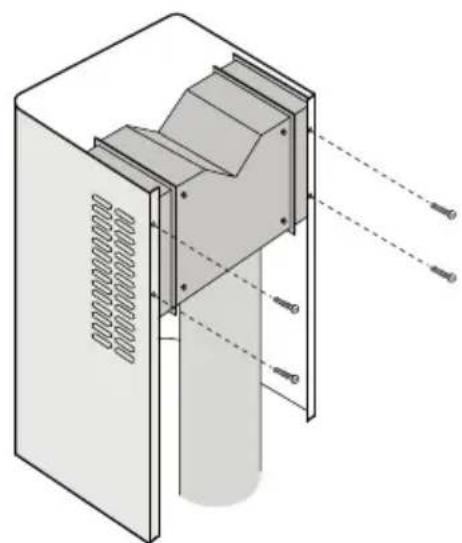
5b - Connect the air outlet pipe to the air vent of the hood. - Use a flexible pipe and lock it to the air vent of the hood with a metal hose clamp - Fig.11 (pipe and clamp are not provided). - For exhaust hoods, turn the upper flue over so that the air exhaust grid is in the lower section (Fig.12).
5c - Plug in the hood. Insert the extension flues setting them on the hood; extend the upper flue to the ceiling and secure with the 2 screws (H) - Fig.13.
INSTALLATION IN FILTERING VERSION: Prepare the power supply within the telescopic flues (for the electrical connection, follow all the other instructions on the "Warnings" sheet).
Fixing to the wall: for fixing to the wall refer to the instructions for the ducting version (see points 2, 3, 4), then continue with the instructions below.
Fixing the telescopic flues: - Assemble the tube support using a 4 screws kit (Fig.9); - Then, by means of the screw anchors and screws (F) provided, fix the bracket to the ceiling in such a way that it is positioned along the axis with your hood (Fig.10). - Mount the flange on the hood in correspondence to the air outlet point (Fig.14). - Take the air baffle and fit a flexible pipe to it (125 mm diameter) locking it with a metal hose clamp (pipe and clamps are not provided). Fit the air baffle to the upper flue (Fig.15) with 4 screws.
- Connect the flexible pipe to the flange on the air vent (Fig.16). - Plug in the hood. Insert the extension flues setting them on the hood; extend the upper flue to the ceiling and secure with the 2 screws H (Fig.13). - Install the charcoal filter fitting the two filter clips in their housings (Fig.17) and turning the filter upward.
OPERATION
Depending on the model, the unit is equipped with the following controls:
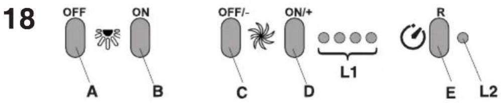
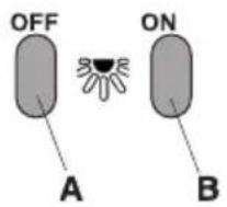
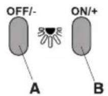
CONTROLS shown in Fig.18:
A) Turns the LIGHTS off
B) Turns the LIGHTS on.
C) Decreases speed down to minimum speed. If pressed for 2" the motor is turned off.
D) Activates the motor (calling the last speed used) and increases the speed until reaching maximum..
E) FILTER ALARM/TIMER RESET: when pressing the key during display of the filter alarm (motor off) it resets the hour counter. When pressing the key when the motor is running, the TIMER is activated and the hood will automatically be switched off after 5 minutes.
L1) The 4 green LEDs indicate the running speed.
L2) When the LED is red (motor off) it indicates the FILTER ALARM. When the LED is green (flashing) it indicates that the TIMER has been activated with the key E.
FILTER ALARM:
After 30h of operation, the LED L2 turns RED. It indicates that the grease filters need to be cleaned.
After 120h of operation, the LED L2 turns RED and flashes; It indicates that the grease filters need to be cleaned and the charcoal filters replaced.
After cleaning the grease filters (and/or replacing the charcoal filters), restart the hour counter (RESET) by pressing the key E during display of the filter alarm.
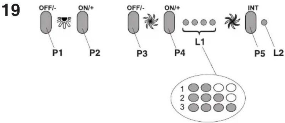
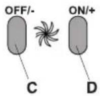
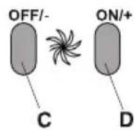
CONTROLS shown in Fig.19:
P1) OFF/- Lights: Decreases light intensity down to minimum intensity. If pressed for 2 seconds, the lights are switched off.
P2) ON/+ Lights: Switches on the lights using the last brightness level set (prior to the last time the lights were switched off). Increases light intensity up to maximum intensity.
P3) OFF/- Engine: Decreases speed down to minimum speed. If pressed for 2 seconds, the engine is switched off. If pressed for 2 seconds when FILTER ALARM is active, HOUR metering is reset.
P4) ON/+ Engine: Switches on the engine using the speed set (prior to the last time the engine was switched off). Increases the speed of the engine up to maximum speed (NON INTENSIVE). If pressed for 2 seconds, the 5-minute Timer is activated and HIGHLIGHTED by flashing speed indication LEDs. If pressed for 2 seconds when the Timer is active, it is ELIMINATED.
P5) INT: Only functions with ENGINE ON. If pressed once, it activates the FIRST intensive speed; if pressed for a second times, the SECOND intensive is activated; if pressed for a THIRD time, the speed set prior to the intensive (that is one of the first 4) is set again.
L1) The 4 green LEDs indicate the running speed.
L2) 2-colour LED: GREEN indicates the First Intensive Speed RED indicates the Second Intensive Speed. FILTER ALARM:
After 30h of operation, the first 2 leds (L1) flash; it indicates that the grease filters need to be cleaned.
After 120h of operation, - the last 2 leds (L1) flash; It indicates that the grease filters need to be cleaned and the charcoal filters replaced. After cleaning the grease filters (and/or replacing the charcoal filters), restart the hour counter (RESET) by pressing the key P3 during display of the filter alarm.
CONTROLS of Fig.20:
A) Turns the lights off.
B) Turns the lights on.
C) Reduces the motor speed until reaching zero. If pressed for 2" when the Filter Alarm is active, the HOUR counter is reset.
D) Drives the motor (calling the last speed used) and increases the speed until reaching maximum.
E) Activates/deactivates the sensor (AUTOMATIC or MANUAL mode). In Automatic mode the sensor is active and the letter "A" appears on the display (L).
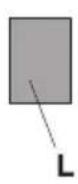
L) Display:
- signals the running speed
- signals Automatic mode by displaying the letter “A”. When the motor speed is changed, the running speed is displayed flashing 3 times, and then the letter “A” reappears.
- signals the filter alarm (with motor off) by displaying the central segment for 30".
FILTER ALARM: Displayed for 30" when the motor is off:
After 30h of operation the central segment lights up on the display; It indicates that the grease filters need to be cleaned. After 120h of operation, the central segment flashes on the display; It indicates that the grease filters need to be cleaned and the charcoal filters replaced. After cleaning the grease filters (and/or replacing the charcoal filters), restart the hour counter (RESET) by pressing the key C during display of the filter alarm.
GAS SENSOR SENSITIVITY: The sensitivity of the sensor can be modified to suit your requirements. To modify the sensitivity, the appliance must be in manual mode (i.e. the running speed and not the letter "A" must appear on the display); If not, press the key E. Modify the sensitivity by simultaneously pressing the keys D and E. The set sensitivity
is indicated on the display. By means of the buttons C(-) and D(+) the desired sensitivity is set Store the "new" sensitivity by pressing the key E.
ATTENTION: TO PREVENT DAMAGING THE SENSOR, DO NOT USE SILICONE PRODUCTS NEAR THE HOOD!
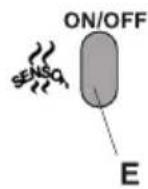
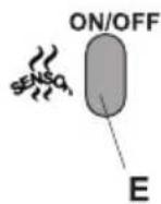
CONTROLS of Fig. 21:
A) Reduces the luminous intensity to minimum. When the key is pressed for 2" the lights go off.
B) Switches on the lights calling the last level of luminous intensity set. Increases the luminous intensity to maximum.
C) Reduces the motor speed until reaching minimum. If pressed for 2", the motor is switched off.
If pressed for 2" when the Filter Alarm is active, the HOUR counter is reset.
D) Drives the motor (calling the last speed used) and increases the speed until reaching maximum.
E) Activates/deactivates the sensor (AUTOMATIC or MANUAL mode). In Automatic mode the sensor is active and the letter "A" appears on the display (L).
L) Display:
- signals the running speed.
- signals Automatic mode by displaying the letter "A". When the motor speed is changed, the running speed is displayed flashing times, and then the letter "A" reappears.
- signals the filter alarm (with motor off) by displaying the central segment for 30".
FILTER ALARM: Displayed for 30" when the motor is off:
After 30h of operation, the letter “F” appears on the display; It indicates that the grease filters need to be cleaned. After 120h of operation, the letter “F” flashes on the display; It indicates that the grease filters need to be cleaned and the charcoal filters replaced.
After cleaning the grease filters (and/or replacing the charcoal filters), restart the hour counter (RESET) by pressing the key C during display of the filter alarm.
GAS SENSOR SENSITIVITY: The sensitivity of the sensor can be modified to suit your requirements. To modify the sensitivity, the appliance must be in manual mode (i.e. the running speed and not the letter "A" must appear on the display); If not, press the key E.
Modify the sensitivity by simultaneously pressing the keys D and E. The set sensitivity is indicated on the display. By means of the buttons C(-) and D(+) the desired sensitivity is set Store the “new” sensitivity by pressing the key E.
ATTENTION: TO PREVENT DAMAGING THE SENSOR, DO NOT USE SILICONE PRODUCTS NEAR THE HOOD!
Grease filters: special attention must be given to the grease filters which must be periodically cleaned, whenever the grease filter alarm trips. For instructions of the filter Alarm, refer to the Controls paragraph. Remove the filters as shown in para. 1 and wash with neutral detergent.
Charcoal filters: if the filtering version appliance is used, the charcoal filters will have to be periodically replaced when the charcoal filter alarm trips. For instructions on the filter Alarm, refer to the Controls paragraph. Removing the charcoal filter/s: take away the metallic grille (Fig.3a) and the grease filter (Fig.3b/3c). Remove the coal filter pushing the lock inside, rotate the filter until taking away the two small tongues from their sides (Fig.17).
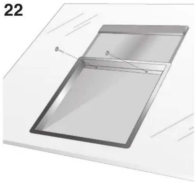
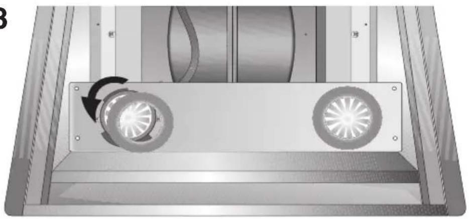
Lighting: to reach the lamps you remove the metallic support tightening the two screws (Fig.22) and moving it oo the right; to replace the halogen lamps tighten the locknut in the anti-clockwise direction and pull out the bulb (Fig.23). Replace the lamps of the same type.
BESCHREIBUNG
A) Desliga as LUZES.
B) Acende as LUZES.
natural_image
Diagram of a mechanical or fluid system with directional arrows indicating flow or movement (no text or symbols present)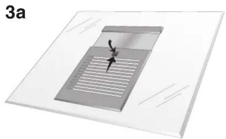
natural_image
3D diagram of a microfluidic device with internal channels and a central valve, labeled '3a' (no text or symbols on the device itself)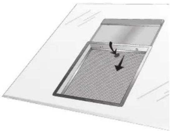
natural_image
Diagram of a microplate with a grid pattern and directional arrows indicating movement (no text or symbols)3b
natural_image
Diagram of a microplate with a grid pattern and directional arrows, labeled '3c' (no text or symbols on the diagram itself)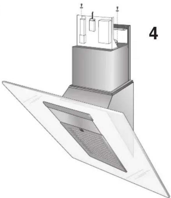
natural_image
3D technical illustration of a mechanical or architectural component with layered structure and ventilation grilles (no text or symbols)5
6
7
8
natural_image
3D technical illustration of a mechanical device with internal components and a fan-like base (no text or symbols)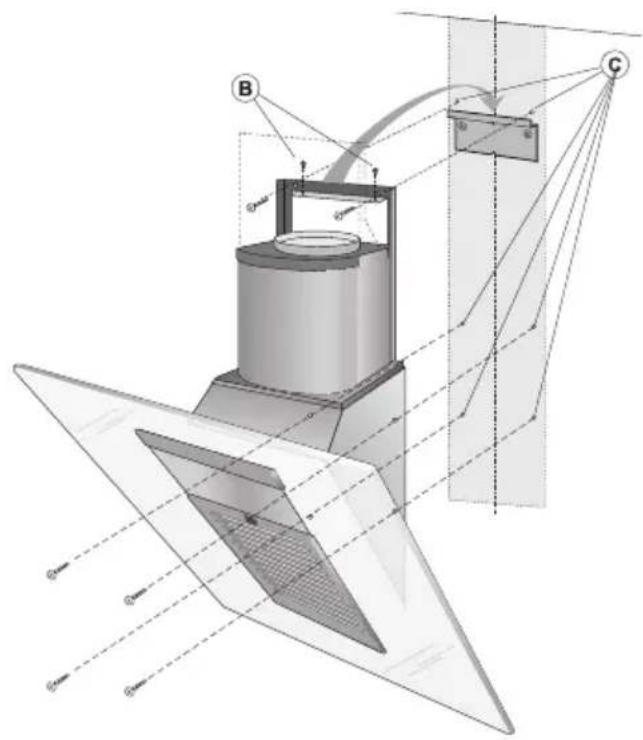
9
natural_image
Mechanical assembly diagram showing two metal frame assemblies with mounting holes and dashed alignment lines (no text or symbols)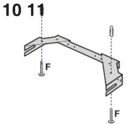
natural_image
Architectural floor plan diagram showing room layout and structural elements (no text or labels)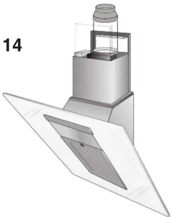
natural_image
3D technical illustration of a mechanical assembly with layered components and a labeled part '14' (no text or symbols on the diagram itself)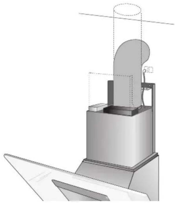
natural_image
Technical illustration of a mechanical assembly with a cylindrical component and base platform (no text or symbols)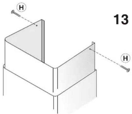
15
natural_image
Technical line drawing of a mechanical assembly with no visible text or symbols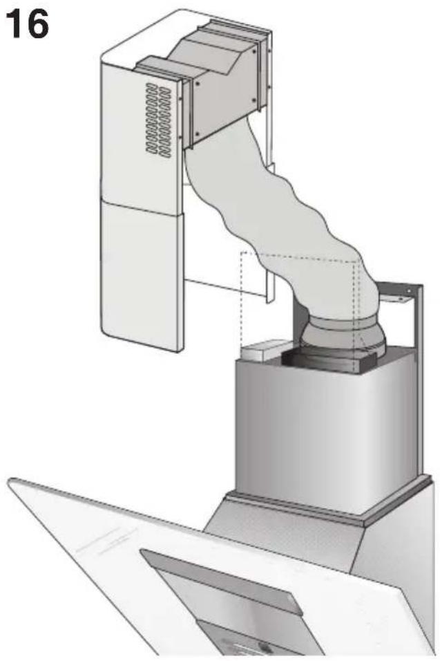
natural_image
Technical illustration of a mechanical device with a coiled duct and fan assembly (no text or symbols)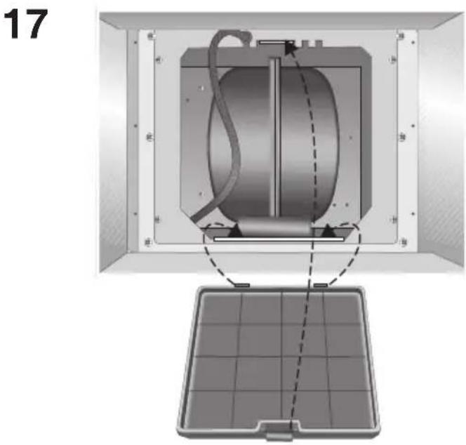
flowchart
graph TD
    subgraph Left_Section
        P1["OFF/-"] --> P2["ON/+"]
        P2 --> P3["OFF/-"]
        P3 --> P4["ON/+"]
        P4 --> L1["L1"]
        L1 --> P5["P5"]
        L1 --> L2["L2"]
    end
    subgraph Right_Section
        P4 --> L1
        L1 --> P5
        L1 --> L2
    end
    P1 -->|P1| P2
    P3 -->|P3| P4
    L1 -->|L1| L2
    style L1 fill:#ccc,stroke:#333
    style L2 fill:#ccc,stroke:#333
    style L1 fill:#ccc,stroke:#333
    style L2 fill:#ccc,stroke:#333
20
21
natural_image
Diagram of a rectangular container with internal structure and dashed lines indicating measurement or alignment (no text or symbols)23
natural_image
Mechanical assembly diagram showing a rotating component with two blades and a central hub (no text or symbols)
Brand : ROSIERES
Model : RHV9102
Category : Basket