
GMD7500M - AV receiver PIONEER - Free user manual and instructions
Find the device manual for free GMD7500M PIONEER in PDF.
| Product Type | Mono subwoofer amplifier |
| Brand | Pioneer |
| Model | GMD7500M |
| Maximum output power | 400 W x 1 (4 Ω) / 800 W x 1 (2 Ω) |
| Continuous output power | 200 W x 1 (4 Ω, 14.4 V, 20 Hz-240 Hz, ≤1% THD) / 400 W x 1 (2 Ω, 14.4 V, 50 Hz, ≤1% THD) |
| Load impedance | 4 Ω (acceptable 2 Ω to 8 Ω) |
| Frequency response | 10 Hz to 30 kHz (+0 dB, -3 dB) |
| Signal-to-noise ratio | 95 dB (IEC-A network) |
| Distortion | 0.03% (10 W, 100 Hz) |
| Low-pass filter | Cutoff frequency 40 Hz to 240 Hz, slope 12 dB/octave |
| Bass boost | 50 Hz, levels 0/6/12 dB |
| Adjustable gain (RCA) | 200 mV to 6.5 V |
| Adjustable gain (speaker) | 0.8 V to 10 V |
| Maximum input level/impedance (RCA) | 6.5 V / 22 kΩ |
| Maximum input level/impedance (speaker) | 10 V / 22 kΩ |
| Supply voltage | 14.4 V DC (10.8 V to 15.1 V acceptable) |
| Grounding | Negative pole |
| Power consumption | 18 A (4 Ω continuous supply) |
| Average current draw | 5.2 A (4 Ω for one channel) / 10.3 A (2 Ω for one channel) |
| Fuse | 40 A x 1 |
| Dimensions (W x H x D) | 245 mm x 56 mm x 200 mm |
| Weight | 2.1 kg (wiring cables not included) |
| Built-in protection | Protection function against excessive outputs and malfunctions |
Frequently Asked Questions - GMD7500M PIONEER
User questions about GMD7500M PIONEER
0 question about this device. Answer the ones you know or ask your own.
Ask a new question about this device
Download the instructions for your AV receiver in PDF format for free! Find your manual GMD7500M - PIONEER and take your electronic device back in hand. On this page are published all the documents necessary for the use of your device. GMD7500M by PIONEER.
USER MANUAL GMD7500M PIONEER
CLASS D MONO AMPLIFIER
AMPLIFICATEUR MONO DE CLASSE D
AMPLIFICATORE MONOFONICO DI CLASSE D
AMPLIFICADOR MONO CLASED
PykoBoDCTBO noIb30BaTeJIa
ThankyouforpurchasingthisPIONEERproduct.
Toensureproperuse,pleasereadthrougthismanualbeforeusingthisproduct. Pleasekeepthemanualinasafeandaccessibleplaceforfuturereference.

Beforeyoustart
Incaseoftrouble3
AboutThisProduct3
Beforeconnecting/installingtheamplifier3

SettingtheUnit
What'swhat5
Settinggainproperly5

Connectingtheunits
Connectiondiagram7
Beforeconnectingtheamplifier7
Connectingthespeakers8
Connectionswhenusingthespeakerinput wire8
Connectingthepowerterminal9
Connectingthespeakeroutput terminals10

Installation
Beforeinstallingtheamplifier11
Exampleofinstallationonthefloormator chassis11

Additional information
Specifications12
Beforeyoustart

Ifyouwanttodisposethisproduct,donotmix itwithgeneralhouseholdwaste.Thereiseaseparatecollectionsystemforusedelectronic productsinaccordancewithlegislationthatrequirespropertreatment,recoveryandrecyclng.
Privatehouseholdsinthememberstates of theEU,inSwitzerland and Norway may return theirusedelectronicproductsfreeofcharge todesignatedcollectionfacilitiesortoaretailer(ifyoupurchaseasimilarnewone).
For countriesnotmentionedabove,please contactyourlocalauthoritiesforthecorrect methodofdisposal.
Bydoingsoyouwillensurethatyourdisposed productundergoesthenecessarytreatment, recoveryandrecyclingandthuspreventpotentialnegativeeffectsontheenvironment andhumanhealth.
Incaseoftrouble
Shouldthisproductfailtooperateproperly, pleasecontactyourdealerornearestauthorizedPioneerServiceStation.
AboutThisProduct
Thisproductisamonoamplifierforsubwoofer.If bothL(left)andR(right)channelsareconnected totheRCAinputofthisproduct,outputismixed becausethisproductisamonoamplifier.
Beforeconnecting/ installingtheamplifier
WARNING
Theuseofaspecialredbatteryandground wireRD-223,availableseparately,isrecommended.Connectthebatterywiredirectlyto thecarbatterypositiveterminal ④ andthe groundwiretothecarbody.
- Thisunitisforvehicleswitha12Vbattery and negativegrounding.Beforeinstallinginrecreationalvehicles,trucksorbuses,checkthe batteryvoltage.
Theblackcableisground.Wheninstalling thisunit,makesuretoconnecttheground wirefirst.Ensurethatthegroundwireisproperlyconnectedtometalpartsofthecar's body.Thegroundwireoftheoneofthisunit mustbeconnectedtothecarseparatelywith differentscrews.lfhrescrewfortheground wireloosensorfallsout,itcouldresultinfire, generationofsmokeormalfunction.
- Useafuseoftheratingprescribed.
- Check the connection of the powersupply and speakers if the use of these separately sold batterywire or the amplifier fuses. Determine and resolve the cause, then replace the fuse with identical equivalent.
- Alwaysinstalltheamplifieronaflatsurface. Donotinstalltheamplifieronasurfacethat isnotflatoronasurfacewithaprotrusion. Doingsocouldresultimalfunction.
- Wheninstallingtheamplifier, donotallow partssuchasextrascrewstogetcaughtbetweentheamplifierandtheautomobile. Doingsocouldcausemalfunction.
- Donotallowthisunittocomeintocontact withliquids. Electricalshockcouldresult. Also,damagetothisunit,smoke,andoverheatingcouldresultfromcontactwithliquids. Thesurfacesoftheamplifierandanyattached speakersmayalsoheatupandcauseminor burns.
- Intheeventofanyabnormality, the power supplytotheamplifieriscutofftoprevent equipmentmalfunction. Ifthisoccurs, switch thesystempowerOFFandcheckthepower supplyandspeakerconnections. Ifyouareunabletodeterminethecause, pleasecontact yourdealer.
- Disconnectthenegativeterminalofthebatterybeforeinstallation.

CAUTION
- Alwayskeep the volume lowened to hear outside sounds.
- Extendeduseofthecarstereowhiletheengineisatrestoridlingmayexhaustthebattery.
- Connecteithertoftwosubwooferstotheamplifier;1:asubwooferwitha250Worlargernominalinputandanimpedance4Ω, or 2 : asubwooferwitha420Worlargernominalinputandanimpedance2Ω.Ifthenominalinputandimpedanceareoutoftheaboveranges,thesubwoofermaycatchfire,emitsmokeorbecomedamaged.
SettingtheUnit
What'swhat
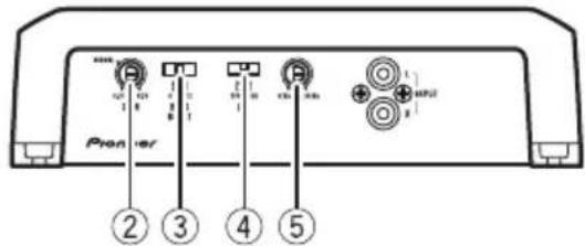
Frontside
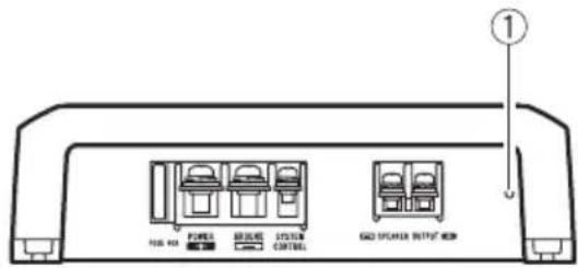
Rearside
Toadjusttheswitch,useaflatheadscrewdri- verifneeded.
①Powerindicator
Thepowerindicatorlightsuptoindicate powerON.
②GAIN(gain)control
Ifoutputremainslow,evenwhenthecar stereovolumeisturnedup,turncontrolsto lowerlevel. Ifdistortionoccurswhenthecar stereovolumeisturnedup, turntheseconrolstohigherlevel.
-
ForusewithanRCAequippedcarstereo (standardoutputof500mV),settothe NORMALposition.ForcewithanRCA equippedPioneercarstereo,withmax. outputof4Vormore,adjustlevelto matchthatofthecarstereooutput.
-
Ifyouheartoomuchnoisewhenusing thespeakerinputterminals,turnthe gaincontroltohigherlevel.
③ BASSBOOST(bassboostlevelcontrol) switch
You can select tabassboostlevel from 0 dB, 6 dB and 12 dB.
④LPF(low-passfilter)switch
Switchthesettingsbasedontheconnected speaker.
- WhentheSubwooferisconnected: SelectON.Thiseliminateshighrange frequency and outputslowrange frequency.
- Whenthefullrangespeakerisconnected:
SelectOFF.OFFoutputstheentirefrequencyrange.
LPF(low-passfilter)cutofffrequency control
You can select acutoffrequency from 40 Hz to 240 Hz.
Settinggainproperly
- Protectivefunctionincludedtoprevent malfunctionoftheunitand/orspeakers duetoexcessiveoutput,improperuseor improperconnection.
- When outputting high volumesoundetc., this function cuts off the output for a few seconds as anormalfunction, but output is restored when the volume of the head unitisturned down.
- Acutinsoundoutputmayindicateimpro-persettingofthegaincontrol.Toensure continuousoundoutputwiththehead unitatahighvolume,setamplifiergain controtoalevelapproprieforthepreout maximumoutputleveloftheheadunit,so that volumecanremainunchangedandto controlexcessoutput.
- Despitecorrectvolumeandgainsettings, theunitsoundstillcutsoutperiodically. In suchcases, please contact the nearest authorized Pioneer Service Station.
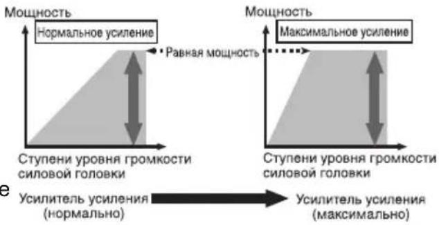
Gaincontrolofthisunit
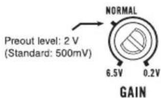
AboveillustrationsshowsNORMALgainsetting.
Relationshipbetweenamplifiergain andheadunitoutputpower
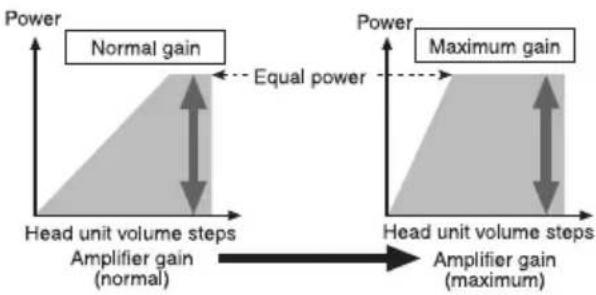
If amplifiergainisraisedimproperly,thiswill simply increasedistortion,withlittleincrease inpower.
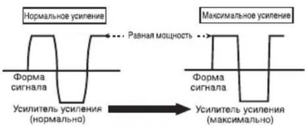
Signalwaveformwhenoutputting at highvolumeusingamplifiergain control
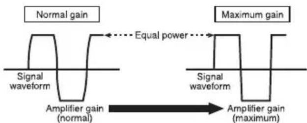
Signalwaveformdistortedwithhighoutput,if youraisethegainoftheamplifierthepower changesonlyslightly.
Connectingtheunits
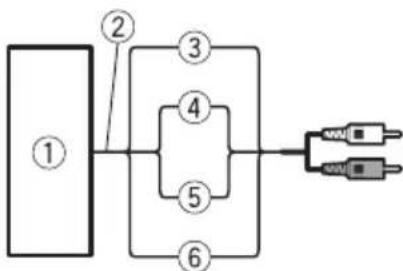
Connectiondiagram
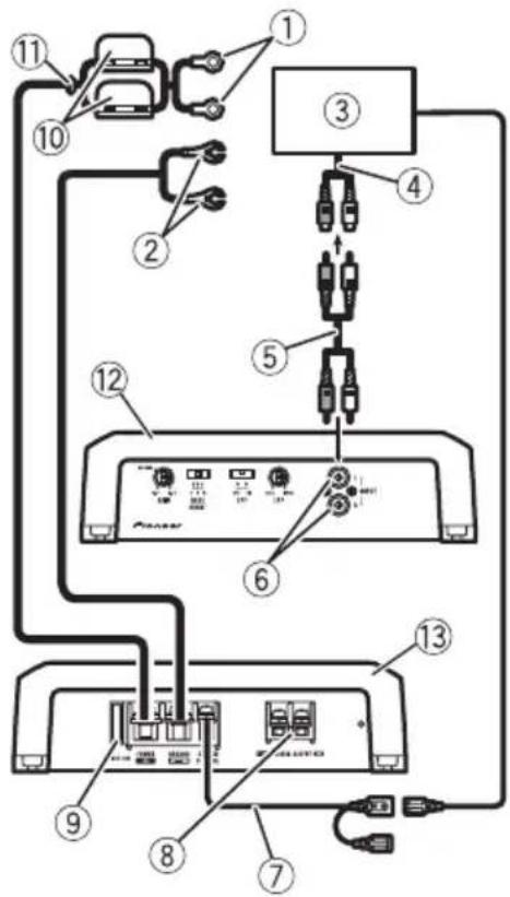
①Specialredbatterywire RD-223(soldseparate
Aftercompletingallotheramplifierconnections,finallyconnectthebatterywireterminal oftheamplifiertothepositive () battery terminal.
②Groundwire(Black)
RD-223(soldseparately)
Connecttoaclean,paint-freemetallocation.
③ CarstereowithRCAoutputjacks(soldseparately)
④ Externaloutput
⑤ConnectingwirewithRCApinplugs(soldseparately)
⑥RCAinputjack
⑦ Systemremotecontrolwire(soldseparately) Connectmaleterminalofthiswiretothesystemremotecontrolterminalofthecarstereo. Thefemaleterminalcanbeconnectedtothe auto-antennarelaycontrolterminal.lfhecar stereolacksystemremotecontrolterminal,
connectthemaleterminaltothepowerterminalviatheignitionswitch.
⑧ Speakeroutputterminals Pleaseseethefollowingsectionforspeaker connectioninstructions.RefertoConnections whenusingthespeakerinputwireonthenthenthpage.
⑨Fuse(40A)
Fuse(30A)×2
①Grommet
12Rearside
③ Frontside

Beforeconnectingthe amplifier

WARNING
- Securethewiringwithcableclampsoradhesivetape.Toprotecttthewiring,Wrapsectionsincontactwithmetalpartsinadhesivetape.
- Nevercuttheinsulationofthepowersupply tofeedpowertootherequipment.Current capacityofthewireislimited.

CAUTION
- Nevershortenanywires, the protection circuit may malfunction.
- Neverwirethespeakernegativecabledirectlytoground.
- Neverbandtogethermultiplespeaker'snegativecables.
- Ifthesystemremotecontrolwireoftheamplifierisconnectedtothepowerterminalviathe ignitionswitch(12VDC),theamplifierwillremainonwiththeignitionwhetherstearstereoisonoroff,whichmayexhaustbattery iftheengineisatrestoridling.
Connectingtheunits
Installandroutetheseparatelysoldbattery wireasfaraspossiblefromthespeakerwires. Installandroutetheseparatelysoldbattery wire,groundwire,speakerwiresandtheamplifierasfarawayaspossiblefromtheantenna,antennacableandtuner.
Connectingthespeakers
Connectthespeakerleadstosuitthemode accordingtothefiguresshownbelow.
One-channeloutput
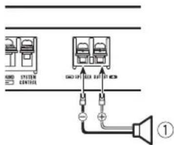
①Subwoofer
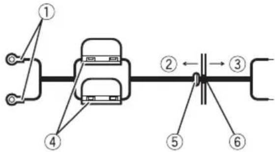
Connectionswhenusing thespeakerinputwire
Connectthecarstereospeakeroutputwires totheamplifierusingthesuppliedspeaker inputwirewithRCApincord.
①CarStereo
②Speakeroutput
③Red:Right
④Black:Right
⑤Black:Left-
⑥White:Left
⑦SpeakerinputwirewithRCApincord TotheRCAinputjackofthisunit

Note
- If speaker wires with an RCA pincord from a headunit are connected to this amplifier, the amplifier will automatically turn on when the headunit is turned on. Whenthe headunit is turned off, the amplifier turns off automatically. This function may not work with some headunits. Insuch cases, please use asystemremotecnrolwire(sold separately). If multiple amplifiers are connected togethersynchronously, connect the headunit and all amplifier viathesystemremotecntrlwire.
- Connectthesystemremotecontrolwirewhen youwishtoonlyturnnonthecarstereo,notthe amplifier.
- This amplifier automatically selects an input signal mode between the RCA level and the speaker level by detecting an input signal.

Connectingtheunits
Connectingthepowerterminal
Theuseofaspecialredbatteryandground wireRD-223,availableseparately,isrecommended.Connectthebatterywiredirectly tothecarbatterypositiveterminal () and thegroundwiretothecarbody.

WARNING
If the battery wire is not securely fixed to the terminal using the terminals screws, there is a risk of overheating, malfunction and injury, including minor burns.
1Routebatterywirefromenginecompartmenttothevehicleinterior.
Aftercompletingallotheramplifierconnections,finallyconnectthebatterywireterminal oftheampliertothepositive () battery terminal.
① Positive () terminal
② Enginecompartment
③Vehicleinterior
④Fuse(30A)×2
⑤InserttheO-ringrubbergrommetintothe vehiclebody.
⑥ Drilla14mmholeintothehvehiclebody.
2Twistthebatterywire,groundwire andsystemremotecntrlwire.
3Attachlugstowireends.Lugsnotsupplied.
Usepliers,etc.,tocrimplugstowires.
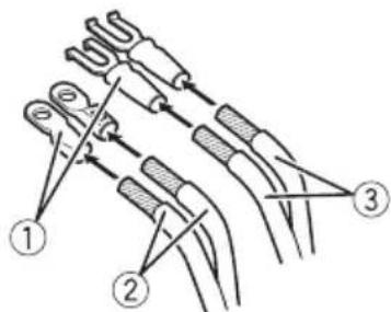
①Lug
② Batterywire
③Groundwire
4Connectthewirestotheterminal.
Fixthewiressecurelywiththeterminal screws.
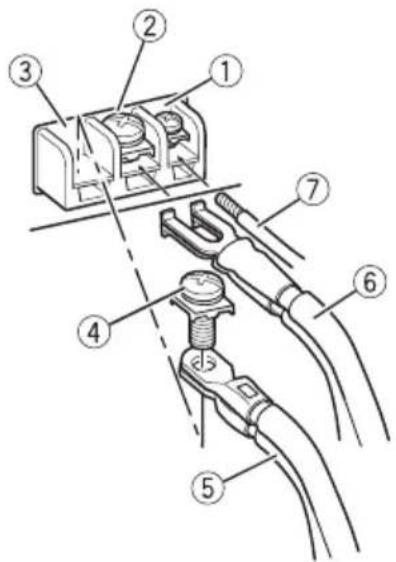
①Systemremotetocontrolterminal
②GNDterminal
③Powerterminal
Connectingtheunits
④Terminalscrews
⑤Batterywire
⑥Groundwire
⑦Systemremotecontrolwire

Connectingthespeaker outputterminals
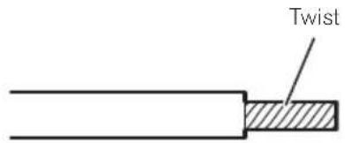
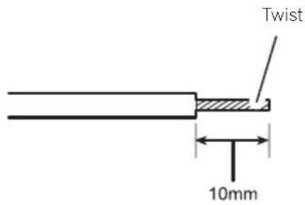
1Exposetheendofthespeakerwires usingnippersoracutterbyabout10mm andtwist.
2Attachlugstospeakerwireends.Lugs notsupplied.
Usepliers,etc.,tocrimplugstowires.
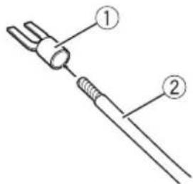
①Lug
②Speakerwire
3Connectthespeakerwiresthespeakeroutputterminals.
Fixthespeakerwiressecurelywiththeterminalscrews.
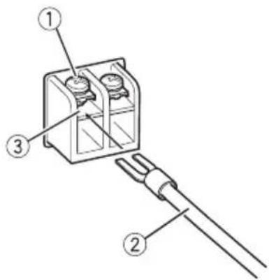
①Terminalscrews
②Speakerwires
③Speakeroutputterminals
Beforeinstallingtheamplifier

WARNING
- Donotuseunauthorizedpartsasthismay causemalfunctions.
- Donotinstallthisunitwhere:
-itmayinterferewithoperationofthevehicle.
-itmaycauseinjurytoapassengersaresultofasuddenstop.
Installtappingscrewsinsuchawaythatthe screwtipdoesnn'touchanywire.Thisisimportanttopreventwiresfrombeingcutbyvibrationofthecar,whichcanresultinfire. - Placeallcablesawayfrommovingparts,such asthegearshiftandseatrails.
- Whendrillingtoinstalltheamplifier,always confirmnopartsarebehindthepaneland protectallcablesandimportantequipment (e.g.fuel/brakelines,wiring)fromdamage.

CAUTION
Toensureproperheatdissipationoftheamplifier,ensurethefollowingduringinstallation:Allowadequatespaceabovetheamplifierforproperventilation.Donotcovertheamplifierwithafloormat orcarpet.
- Placeallcablesawayfromhotplaces,such asneartheheateroutlet.
Theoptimalinstallationlocationdiffersdependingonthecarmodel.Securethempliferatasufficientlyrigidlocation.
- Checkallconnectionsandsystemsbefore finalinstallation.
Afterinstallingtheamplifier, confirmthat the spare tire, jackandtoolscanbeeasilyremoved.
Exampleofinstallationon thefloormatorchassis
1Placethemamplifierinthedesiredinstallationlocation.
Insertthesuppliedtappingscrews(4mm× 18mm)intothescrewwholesandpushonthe screwswithascrewdriversotheymakeanimprintwheretheinstallationholesaretobelocated.
2Drill2.5mm diameter holes at the imprintseither on the carpeted directly on the chassis.
3Installtheamplifierwiththeuseof suppliedtappingscrews(4mm×18mm).
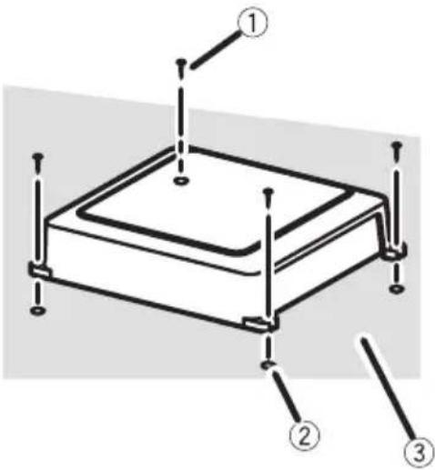
①Tapping-screws(4mm×18mm)
②Drillaa.5mm diameterhole
③ Floormatorchassis
Additionalinformation
Specifications
Powersource.14.4VDC(10.8Vto15.1V allowable)
Groundingsystem.. Negativetype
Currentconsumption.18A(atcontinuouspower, 4Ω)
Averagecurrentdrawn.....5.2A(4Qforonechannel) 10.3A(2Qforonechannel)
Fuse. 40A×1
Dimensions(W×H×D)...245mm×56mm×200 mm
Weight.21kg(Leadsforwiringnot included)
Maximum power output ....400 W x 1 (4 Ω) / 800 W x 1 (2Ω)
Continuouspoweroutput...200W×1(at14.4V,4Ω,20 Hzto240Hz,≤1%THD)
400W×1(at14.4V,2Ω,50
Hz,≤1%THD)
Load impedance 4Ω (2Ω to 8Ω allowable)
Frequencyresponse.10Hzto30kHz(+0dB,3 dB)
Signal-to-noiseratio. 95dB(IEC-Anetwork)
Distortion.0.03%10W,100Hz)
Lowpassfilter: Cutofffrequency.40Hzto240Hz Cutoffslope.12dB/oc
Bassboost: Frequency. .50Hz Level. 0dB/6dB/12dB
Gaincontrol: RCA.200mVto6.5V Speaker. 0.8Vto10V
Maximuminputlevel/impedance: RCA. .6.5V/22kΩ Speaker. .10V/22kΩ

Notes
- Specificationsandthedesignaresubjectto modificationswithoutnotice.
Theaveragecurrentdrawnisnearlythemaximumcurrentdrawnbthisisunitwhenanaudiosignalinput.Usethisvaluewhenworkingouttotalcurrentdrawnbymultiplepoweramplifiers.
Tabledesmatieres
Deversterkingsfactor (gain)instellen
OTHOWeHne Ko3ΦΦnUeHtA yCnJIeHnYcNlIteJI N BbIXoHOn MOuHOCTHOCHOBHOrO yCTpOiCTBa
Ipn qpe3MepHom NOBbIeHnn KO3oOuNHeHa YcUHeHn pe3KO yBeJIuHNaIbOTc NCKaKeHn,a MOUHOCTb NOBbIuaETCr He3HaHTeJbHo.
ΦopMa cnHaJa Ha BbIXOe npn BbvICOKOM yPOBHe rPOMKOCTH, CO3daHHOM C NOMoUbIO peryIaTopa KO3ΦΦnCnEHTa ycJIeHnYcNlnteJr
UckaeHHaOpMa CnHaJa npBbICOKOM ypoBHe rPOMKoCTn.Pnp NOBbiJeHm K03Φ- cHnueHtA ycJIeHnY cHJNTeJI MOHOCb N3MeHReTc He3HaHTeJIbHd
PerynpoBka Ko3ΦΦnueHtayCHeHna DaHHoro yCTpO'CTBa

Ha pncyHke Bblwe noka3aHO noIooKeHne peruJrTopa ycJIeHnHa ypoBHe NORMAL.
Ipeed nodkloucheHneM ycnJInteJ

NPEyPPEKDEHNE
3aKpEnIte npoBoDa npn nOMOu 3aXIMOB Hnn N3OJauHHOJ JeHTb.I.ДЯ 3aUHTbI npoBOdkn 3aN3OJnpuTe npoBoDa B MeCTax IX COpnKOCHOBeHna C MeTaNlHuECKMn DeTaJIaMn.
He Hapuatae n3oJauIO npOBOOB nTahnA DnI NOaun nTaNHa Ha dpyroe o6OpydoBaHne.IpObOda ImeOT orpaHnueHHyO dony-CTIMyIO Harpy3Ky No TOky.

BHIMAHNE
-3anpeaetcyaKopauNbBaTb npoBoda,ueNB 3aunTb MoKeT BblTN N3 CTPOJ.
MaKcImaJIbHaB BbIXoHHa MoUHOCTb 400BT×1(4Ω)/800BT× 1(2Ω)
HOMHaJIbHaB BbIXoDHa MOnuOcTb 200BT×1 (npn14,4B,4 Ω,ot20ΓUdo240ΓU,cym- MapHoe 3NaueHne Ko3ΦΦn UHeNTa HeINHeNbIX NCKaKeHn ≤ 1% 400BT×1 (npn14,4B,2 Ω,50ΓU,cymMapHoe 3Ha- YeHne K03ΦΦnUeHTa HeINHeNbIX NCKaKeHn ≤ 1%)
COnpoTnBHeHne Harpy3Kn 4Ω(DOnyctnMo-ot2Ω do8Ω)
AmnntyndHo-actoTHa xapaKTeepuCTnka 10Tcdo30Kt(+0d5, -3D6)
OTHOeHne cHnA/Um ... 95 d (ceTb IEC-A)
UckaeHne 0,03% (10 Bt, 100 T)
Фильтpr Hn3knx YacToT: Yactota cpe3a .OT 40 Tcdo 240 Tc KpyTu3Ha xapaKTePncTnK n cpe3a -12 D6/OKT
YcHHeHHe HnKHX 3ByKObBix YactOT: Yactota .50U ypoBeHb .0D6/6D6/12D6
PerylnpOBka K0aΦΦnueHtaycHHeHnRA RCA . 200 mB do 6,5 BrpoMKorOBopntb . 0T 0,8 Bdo 10B
MaKcHMaJIbHa amnIHTyda BXoJHO rHana /conpoTnBHeHne: RCA 6,5 B/22 KΩ POMKOROBOpTeNb 10 B/22 KΩ
Приимechаиме:
B COOTBETCTBUN co CTAbEi 53aKoHa PocnCKoI Φeepaun "O 3aUInTe npab noTpe6nteJ"n NocTaHOBJIeHEmnpaHTeJIbCTBa PocnCKoI Φeepaun N9720ot 16.06.97kompanna PioneerEuropeNVorOBapuBaET cJeDyUoIcn cPOK cLyXbbl3deIIN,oΦNuaJIbHO NOCTABJIeEMbIX HaPOCCNCKN pBIHOK.
ABym06nJIbHa 3neKtpoHnka:6 neT Dpyrue n3dEInn (HayuHnKn,Mnkpofohbl n T.n.):5JeT

Ppimechnna
XapakTepeNCTnKn N KOHCTpyKuMa MOryT 6bITb n3MeHeHbI 6e3 npedBapntelbHoro yBeDOMJIeHn.
- CpeHHee 3HaueHHe Toka 6Jn3K K MaKcImMaJIbHOMy 3HaueHIno TOka,Notpe6JrEmOMy DaHHbIM yCTpOInCTBOM,KorDa Ha BXoI NOJaEtCaydNocnHAn.NcNoIb3yInTe 3To 3HaueHHe Npi NODcHTe CymMapHorO TOKa, Notpe6JrEmOro HeCKOJIbKIMN YcNJNTeJIaMm MOUHOCTN.
JaHoe yCTPOINCTBO npOn3BeDeHO B Kntae.


http://www.pioneer.eu
Visit www.pioneer.co.uk (or www.pioneer.eu) to register your product. Visitez www.pioneer.fr (ou www.pioneer.eu) pour enregistrer votre apparéil. Si prega di visitare il site www.pioneer.it (o www.pioneer.eu) per registrarile il prodotto. Visite www.pioneer.es (o www.pioneer.eu) para registrar su producto. Zum Registrieren Ihres Produktés besuchen Sieitte www.pioneer.de (oder www.pioneer.eu). Bezoek www.pioneer.nl (of www.pioneer.eu) om uw producte te registrareren. Nocétinte www.pioneer-rus.ru (ил www.pioneer.eu)對於 picaquin npno6pehenhoro Bamn nndenna.
PIONEERCORPORATION
4-1,MEGURO1-CHOME,MEGURO-KU
TOKYO153-8654,JAPAN
Kopnpaun Paonnp
4-1, Merypo 1-Yome, Merypo-Ky, Tokno
153-8654,Яноня
PIONEERELECTRONICS(USA)INC.
P.O.Box1540,LongBeach,California90801-1540,U.S.A.
TEL:(800)421-1404
PIONEEREUROPENV
Haven1087,Keetberglaan1,B-9120Melsele,Belgium/Belgique
TEL:(0)3/570.05.11
PIONEERELECTRONICSASIACENTREPRELTD.
253AlexandraRoad,#04-01,Singapore159936
TEL:65-6472-7555
PIONEERELECTRONICSAUSTRALIAPTY.LTD.
178-184BoundaryRoad,Braeside,Victoria3195,Australia
TEL:(03)9586-6300
PIONEERELECTRONICSOFCANADA,INC.
300AllstateParkway,Markham,OntarioL3R0P2,Canada
TEL:1-877-283-5901
TEL:905-479-4411
PIONEERELECTRONICSDEMEXICO,S.A.deC.V.
PublishedbyPioneerCorporation.
Copyright20092008byPioneer
Corporation. All rights reserved.
PubliéparPioneerCorporation.Copyright
20092008parPioneerCorporation.Tous
droitsréservés.
PrintedinChina
ImpriméenChine


- ThankyouforpurchasingthisPIONEERproduct.
- Beforeyoustart
- SettingtheUnit
- Connectingtheunits
- Installation
- Additional information
- Incaseoftrouble
- AboutThisProduct
- Beforeconnecting/ installingtheamplifier
- WARNING
- CAUTION
- What'swhat
- ①Powerindicator
- ②GAIN(gain)control
- ③ BASSBOOST(bassboostlevelcontrol) switch
- ④LPF(low-passfilter)switch
- LPF(low-passfilter)cutofffrequency control
- Settinggainproperly
- Gaincontrolofthisunit
- Relationshipbetweenamplifiergain andheadunitoutputpower
- Signalwaveformwhenoutputting at highvolumeusingamplifiergain control
- Connectiondiagram
- Beforeconnectingthe amplifier
- Connectingthespeakers
- One-channeloutput
- Connectionswhenusing thespeakerinputwire
- Note
- Connectingthepowerterminal
- 1Routebatterywirefromenginecompartmenttothevehicleinterior.
- 2Twistthebatterywire,groundwire andsystemremotecntrlwire.
- 3Attachlugstowireends.Lugsnotsupplied.
- 4Connectthewirestotheterminal.
- Connectingthespeaker outputterminals
- Beforeinstallingtheamplifier
- Exampleofinstallationon thefloormatorchassis
- 1Placethemamplifierinthedesiredinstallationlocation.
- 2Drill2.5mm diameter holes at the imprintseither on the carpeted directly on the chassis.
- 3Installtheamplifierwiththeuseof suppliedtappingscrews(4mm×18mm).
- Additionalinformation
- Specifications
- Notes
- Tabledesmatieres
- Deversterkingsfactor (gain)instellen
- OTHOWeHne Ko3ΦΦnUeHtA yCnJIeHnYcNlIteJI N BbIXoHOn MOuHOCTHOCHOBHOrO yCTpOiCTBa
- ΦopMa cnHaJa Ha BbIXOe npn BbvICOKOM yPOBHe rPOMKOCTH, CO3daHHOM C NOMoUbIO peryIaTopa KO3ΦΦnCnEHTa ycJIeHnYcNlnteJr
- PerynpoBka Ko3ΦΦnueHtayCHeHna DaHHoro yCTpO'CTBa
- Ipeed nodkloucheHneM ycnJInteJ
- NPEyPPEKDEHNE
- BHIMAHNE
- Приимechаиме:
- Ppimechnna
- http://www.pioneer.eu
- PIONEERCORPORATION
- Kopnpaun Paonnp
Brand : PIONEER
Model : GMD7500M
Category : AV receiver