PDM4210 - TV YAMAHA - Free user manual and instructions
Find the device manual for free PDM4210 YAMAHA in PDF.
| Product type | High-definition plasma television (plasma screen monitor) |
| Brand and model | YAMAHA PDM4210 |
| Screen size | 42 inches (diagonal 1059 mm, 922 x 522 mm) |
| Native resolution | 1024 (H) x 1024 (V) pixels |
| Aspect ratio | 16:9 |
| Dimensions (without stand) | 1030 (W) x 636 (H) x 91 (D) mm |
| Weight (without stand) | 34.9 kg |
| Power supply | AC 100-240 V, 50/60 Hz |
| Power consumption | 365 W (max), less than 3 W in standby (RGB1) or less than 1 W (RGB2 100-120 V) |
| Audio output | 12 W + 12 W (6 Ω) |
| Input connectors | RGB1 (DVI-D), RGB2 (D-sub 15-pin), AV1-4 (Composite, S-Video, Component, SCART), audio (stereo mini-jack) |
| Compatible signals | PC: 640x400 to 1600x1200 (UXGA); Video: PAL, SECAM, NTSC, 480i/p, 576i/p, 1080i, 720p |
| Main functions | High-performance digital processor, remote control, OSD display, automatic image adjustment, display modes (Full, Normal, Real, Zoom 1-3), power saving mode, anti-image retention functions (shutter, inverse, white sleep), optional video unit support |
| Cleaning and maintenance | Turn off and unplug; use a soft, slightly damp cloth (warm water); do not use abrasive or alcohol-based detergents |
| Safety | Do not block ventilation, do not expose to moisture, use a grounded outlet, do not disassemble, call a qualified installer for wall mounting |
| Spare parts and repairability | Options: wall mount bracket PWK-242, video unit PTB-4210; in case of problems, contact your dealer |
| Operating ambient temperature | 5°C to 35°C |
| Relative humidity | 20% to 80% (without condensation) |
Frequently Asked Questions - PDM4210 YAMAHA
User questions about PDM4210 YAMAHA
0 question about this device. Answer the ones you know or ask your own.
Ask a new question about this device
Download the instructions for your TV in PDF format for free! Find your manual PDM4210 - YAMAHA and take your electronic device back in hand. On this page are published all the documents necessary for the use of your device. PDM4210 by YAMAHA.
USER MANUAL PDM4210 YAMAHA
Thank you very much for purchasing the Yamaha High Definition Plasma Monitor.
Before using your monitor, please carefully read this manual so you will know how to operate the monitor properly. Keep this manual in a safe place. You will find it useful in the future.
Notes on Installation Work:
This product is marketed assuming that it is installed by qualified personnel with enough skill and competence. Always have an installation specialist or your dealer install and set up the product. YAMAHA cannot assume liabilities for damage caused by mistake in installation or mounting, misuse, modification or a natural disaster.
Note for Dealers:
After installation, be sure to deliver this manual to the customer and explain to the customer how to handle the product.
Notes about This Manual
This information in this manual is subject to change without notice.
- While meticulous care has been taken in the preparation of this manual, you are requested to notify your dealer or us should you have any comments, views or questions about our product.
- Fully understand the prerequisites to using the product, such as hardware and software specifications and constraints, in using the product. We are not held liable for damages caused by improper handling of the product.
- Reproduction of this manual in whole or in part without our prior written permission is prohibited.
The product names mentioned in this manual may be trademarks or registered trademarks of their respective owners.
READ ALL INSTRUCTIONS CAREFULL. KEEP THIS USER'S MANUAL FOR FUTURE REFERENCE.
For future reference, record the serial number of your monitor.
SERIAL NO.
The serial number is located on the rear of the monitor.
FEATURES
Large-screen, high-definition plasma display panel
The 42-inch colour plasma display panel, with a resolution of 1024 (H) x 1024(V) pixels, creates a high-definition, large-screen (aspect ratio : 16:9) and low-profile flat display. Free from electromagnetic interferences from geomagnetic sources and ambient power lines, the panel produces high-quality display images free from colour misconvergence and display distortion.
High Performance Digital Processor
A wide range of personal computer signals can be handled, from 640 x 400, 640 x 480 VGA to 1600 x 1200 UXGA.
Easy-to-use remote control and on screen display system
The remote control included eases the work of setting display controls. Further, the on-screen display system, displays the status of signal reception and display control settings in an easy-to-view fashion.
TruBass TruBass
TruBass, SRS and (O) symbol are trademarks of SRS Labs, Inc. TruBass technology is incorporated under license from SRS Labs, Inc.
About the Optional Video Unit
The following functions can be obtained by connecting the optional video unit.
(1) A Composite/S video terminal and two component terminals have been added. A composite video output terminal is also provided as a monitoring output.
(2) A wide range of devices other than personal computers can also be connected.
(3) It is possible to switch the component terminal to RGB input from the Menu screen.
(4) A SCART terminal is also provided for the signal of the European standard. It operates as composite/S/RGB input terminal, or video output terminal.
Options
Ask your local retail dealer for further details on the following optional attachments.
-
Wall Mounting Unit PWK-242
Video Unit PTB-4210 -
This User's Manual was printed before final product development. After printing, some product specifications may change due to operational upgrades and other reasons. In this case, the specifications of the product itself will take precedence over the specifications in this manual.
- TRADEMARK ACKNOWLEDGEMENT
VGA and XGA are registered trademarks of International Business Machines Corporation.
APPLE and Macintosh are registered trademarks of Apple Computer, Inc.
All brand or product names are trademarks or registered trademarks of their respective holders.
CONTENTS
FEATURES 2
CAUTION:READ THIS BEFORE OPERATING YOUR UNIT. 3
PRECAUTIONS 7
COMPONENT NAMES 8
Main Unit 8
Remote control 9
Loading Batteries 9
Handling the Remote Control 9
INSTALLATION INSTRUCTIONS 10
Installation 10
Anti-tumble measures 10
Connecting to a PC 11
Power Cord Connection 12
OPERATINGINSTRUCTIONS 13
Turning Power On and Off 13
Input Switching 14
Volume Adjustment 14
Audio Mute 14
Size Switching 15
Input Signal Screen Display 15
Automatic Adjustment of Screen Position and the Clock 16
Independent Operation of Multiple Monitors 16
Using the Menu Screen 16
PICTURE MENU. 17
AUDIO MENU. 18
TIMER MENU 18
FUNCTION MENU 19
SETUP MENU 20
LANGUAGE MENU 21
OTHER FEATURES 21
Automatic Store 21
Signal Check 22
Power Save Mode 22
IMAGE RETENTION OF PLASMA DISPLAY PANEL 23
NOTES 23
TROUBLESHOOTING 24
Symptoms That Appear to be Failures 24
Actions to Correct Abnormal Displays 26
PRODUCT SPECIFICATIONS 27
Signal Input 27
Recommended Signal List 28
SUPPLEMENT 30
Optional Video Unit Function 31
Optional Tuner Unit Function 43
CAUTION: READ THIS BEFORE OPERATING YOUR UNIT.
This Plasma monitor has been designed and manufactured to meet international safety standards, but like any electrical equipment, care must be taken if you are to obtain the best results and safety is to be assured.
Before using this product, please read and understand the Safety Instructions thoroughly to ensure correct usage, and follow all the instructions.
Never use the monitor if a problem occurs.
Abnormal operations such as smoke, strange odor, no image, no sound, excessive sound, damaged casing, elements, cables, penetration of liquids or foreign matter, etc. can cause a fire or electrical shock.
In such case, immediately turn off the power switch and then disconnect the power plug from the power outlet. After making sure that the smoke or odor has stopped, contact your dealer. Never attempt to make repairs yourself because this could be dangerous.
Do not insert liquids or foreign objects.
Penetration of liquids or foreign objects could result in fire or electrical shock. Use special caution in households where children are present.
If liquids or foreign objects should enter the projector, immediately turn off the power switch, disconnect the power plug from the power outlet and contact your dealer.
- Do not place the monitor in a bathroom.
- Do not expose the monitor to rain or moisture.
Do not place flower vases, pots, cups, cosmetics, liquids such as water, etc on or around the monitor. - Do not place metals, combustibles, etc on or around the monitor.
Never disassemble or modify the monitor.
The monitor contains high voltage components. Modification could result in fire or electrical shock.
- Never remove any fixed cover.
Do not give the monitor any shock or impact.
If the monitor should be shocked and/or broken, it could result in an injury, and continued use could result in fire or electrical shock.
If the glass panel is broken or damaged, immediately turn off the power switch, disconnect the power plug from the power outlet and contact your dealer.
Do not place the monitor on an unstable surface.
If the monitor should be dropped and/or broken, it could result in an injury, and continued use could result in fire or electrical shock.
- Do not place the monitor on an unstable, slanted or vibrating surface such as a wobbly or inclined stand.
Do not obstruct the ventilation of the monitor.
If the ventilation is obstructed during the operation of the monitor or just after switching off the power, it could result in damage and shorten the lifespan of your monitor due to overheating. Make sure there is ample ventilation.
- Keep a space of 100mm (10cm) or more between the sides, rear and top of the monitor and other objects such as walls.
- Do not place anything around ventilation openings of the monitor.
- Never block ventilation openings.
- Do not put the plasma display panel side up.
- Do not cover the monitor with a tablecloth, etc.
- Do not place the monitor on a carpet or bedding, or near a curtain.
Use only the correct power outlet.
Incorrect power supply could result in fire or electrical shock. Use only the correct power outlet depending on the indication on the monitor and the safety standard.
- The enclosed power cord must be used depending on the power outlet to be used.
Be cautious of the power cord connection.
Incorrect connection of the power cord could result in fire or electrical shock.
- Do not touch the power cord with a wet hand
- Check that the connecting portion of the power cord is clean (with no dust), before using. Use a soft and dry cloth to clean the power plug.
- Insert the power plug into a power outlet firmly. Avoid using a loose, unsound outlet or contact failure.
- Do not cut off the fitted power plug, the removal of which could lead to impaired performance. If you wish to extend the lead, obtain an appropriate extension lead or consult your dealer.
- Should you require replacing the fuse in the molded plug with a new fuse, then please replace with new one of the same value, type and approval as the original. Ensure the fuse cover is returned to its original position.
Be sure to keep safety ground connection.
Connect the ground terminal of AC inlet of this monitor with the ground terminal provided at the power outlet using the enclosed power cord. If the provided plug does not fit your outlet, consult an electrician for replacement of the obsolete outlet.
Be careful in handling the power cord and external connection cables.
If you keep using a damaged the power cord or cables, it can cause a fire or electrical shock. Do not apply too much heat, pressure or tension to the power cord and cables.
If the power cord or cables are damaged (exposed or broken core wires, etc.), contact your dealer.
- Do not place the monitor or heavy objects on the power cord and cables. Also, do not place a spread, cover, etc, over them because this could result in the inadvertent placing of heavy objects on the concealed power cord or cables.
- Do not pull the power cord and cables. When connecting and disconnecting the power cord or cables, do it with your hand holding the plug or connector.
- Do not place the cord near the heater.
- Do not touch the power plug just after disconnecting it from the power outlet to prevent electric shock.
- Do not touch the power plug when lightening is close to you.
- Avoid coiling the power cord and bending it sharply.
- Protect the power cord from being walked on, pinched particularly at plugs, conveniences receptacles, and the point where they exit from the apparatus.
- Do not modify the power cord.
CAUTION: READ THIS BEFORE OPERATING YOUR UNIT. (continued)
Be careful in handling the battery of the remote control.
Incorrect handling of the battery could result in fire or personal injury. The battery may explode if not handled properly.
- Keep the battery away from children and pets. If swallowed consult a physician immediately for emergency treatment.
- Do not allow the battery to be exposed to fire or water.
- Avoid fire or high-temperature environment.
- Do not hold the battery with metallic tweezers.
- Keep the battery in a dark, cool and dry place.
- Do not short circuit the battery
- Do not recharge, disassemble or solder the battery.
- Do not physically impact the battery.
- Use only the battery specified in the manual of this monitor.
- Make sure the plus and minus terminals are correctly aligned when loading the battery.
If you observe a leakage of the battery, wipe out the liquid and then replace the battery. If the liquid adheres your body or clothes, rinse well with water. - Obey the local laws on disposing the battery.
FOR THE CUSTOMERS IN THE U.K.
THIS PRODUCT IS SUPPLIED WITH A TWO PIN MAINS PLUG FOR USE IN MAINLAND EUROPE. FOR THE U.K. PLEASE REFER TO THE NOTES ON THIS PAGE.
IMPORTANT FOR UNITED KINGDOM
WORDING FOR CLASS I EQUIPMENT INSTRUCTION BOOKS AND LABELS
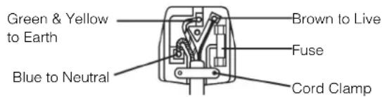
The mains lead on this equipment is supplied with a molded plug incorporating a fuse, the value of which is indicated on the pin face of the plug. Should the fuse need to be replaced, an ASTA or BSI approved BS 1362 fuse must be used of the same rating. If the fuse cover is detachable never use the plug with the cover omitted. If a replacement fuse cover is required, ensure it is of the same colour as that visible on the pin face of the plug. Fuse covers are available from your dealer.
DO NOT cut off the mains plug from this equipment. If the plug fitted is not suitable for the power points in your home or the cable is too short to reach a power point, then obtain an appropriate safety approved extension lead or consult your dealer.
Should it be necessary to change the mains plugs, this must be carried out by a competent person, preferably a qualified electrician.
If there is no alternative to cutting off the mains plug, ensure that you dispose of it immediately, having first removed the fuse, to avoid a possible shock hazard by inadvertent connection to the mains supply.
WARNING: THIS EQUIPMENT MUST BE EARTHED IMPORTANT
The wires in the mains lead are coloured in accordance with the following code :
Green and Yellow = Earth, Blue = Neutral, Brown = Live.
As these colours may not correspond with the coloured markings identifying the terminals in your plug, proceed as follows:
The wire which is coloured GREEN and YELLOW must be connected to the terminal in the plug which is marked with the letter E or by the earth symbol coloured GREEN or GREEN and YELLOW.
The wire coloured BLUE must be connected to the terminal marked with the letter N or coloured BLUE or BLACK. The wire coloured BROWN must be connected to the terminal marked with the letter L or coloured BROWN or RED.
Be careful in moving the monitor.
Neglect could result in an injury or damage.
- Do not move the monitor during use. Before moving, disconnect the power plug and all external connections.
- You are advised to move the monitor with two persons.
- Avoid any impact or shock to the monitor; particularly take care of glass screen.
Do not put anything on top of the monitor.
Placing anything on the monitor could result in loss of balance or falling, and cause an injury or damage. Use special caution in households where children are present.
Avoid a humid or dusty place.
Placing the monitor in a smoke, a highly humid, dusty place, oily soot or corrosive gas could result in fire or electrical shock.
- Do not place near the kitchen, a humidifier or other place where there is oil, smoke or humidity.
Avoid a high temperature environment.
The heat could have adverse influence on the monitor and other parts, and could result in transformation, melting or fire.
- Do not place the monitor, the remote control and other parts in direct sunlight or near a hot object such as heater, etc.
- Do not put the monitor in a place where the temperature is widely changing.
Remove the power cord for complete separation.
- For safety purposes, disconnect the power cord if the monitor is not to be used for prolonged periods of time.
- Before cleaning, turn off and unplug the monitor. Neglect could result in fire or electrical shock.
Installation environment
Do not obstruct a ventilation hole.
Do not put the monitor on carpet or blanket, or near a curtain which has a possibility of obstructing a ventilation hole of the monitor.
Do not put the monitor in the following places.
- Hot places such as near heater, place exposed to the direct rays of the sun.
- A place where the temperature is widely changing.
- Places with soot, dust or high humidity.
Poor air ventilation place. - Place near fire.
- A wet place such as bathroom, or shower room.
- Place where you can trip over it.
Always vibrating or strongly vibrating places.
Distorted or unstable places.
How to view the monitor
If you use the monitor in too dark a room, your eyes may become tired.
Please use it in a reasonably bright room.
Avoid direct rays of the sun to the screen in order to prevent eye fatigue.
Your eyes will get fatigued after viewing the monitor for long period of time.
Relax your eyes by viewing away from the monitor from time to time.
Please watch the monitor in downward direction.
Note on image retention
The plasma monitor illuminates phosphor to display images. The phosphor has a finite illumination life. After extended periods of illumination, the brightness of the phosphor will be degraded to such extent that stationary images would burn-in that part of the screen as grayed-out images.
Tips to prevent such image retention are:
- Do not display images having sharp brightness differences or high-contrast images, such as monochrome characters and graphic patterns, for long.
- Do not leave stationary images appearing for long, but try to refresh them at appropriate intervals of time, or try to move them using screen saver function.
- Turn down the contrast and brightness controls.
How to clean the plasma display panel of the monitor
Before cleaning the monitor, turn off the monitor and disconnect the power plug from the power outlet.
To prevent scratching or damaging the plasma display panel face, do not knock or rub the surface with sharp or hard objects. Clean the screen with a soft cloth moistened with warm water and dry with a soft cloth. If it is not enough, then use a cloth with mild detergent. Do not use harsh or abrasive cleaners.
How to clean the cabinet of the monitor
Use a soft cloth to clean the cabinet and control panel of the monitor. When the plasma monitor is excessively soiled dilute a neutral detergent in water, wet and wring out the soft cloth and afterward wipe with a dry soft cloth.
Never use acid/alkaline detergent, alcoholic detergent, abrasive cleaner, powder soap, OA cleaner, car wax, glass cleaner, etc. especially because they would cause discoloration, scratches or cracks.
Prevention of an obstacle to Radio receivers
This monitor has been designed pursuant to the international EMI standards. This is to prevent a problem to Radio receivers.
- Keep the monitor away from Radio.
- Adjust Radio antennas in order for the monitor not to receive interference.
- The antenna cable of Radio should be kept away from the monitor.
- Use a coaxial cable for antenna.
You can check if this monitor influences Radio receivers by turning off all other equipment other than the monitor.
If you find a problem receiving Radio when using the monitor, check the instructions mentioned above.
Precautions for the cable connection
- Do ensure that all connections, (including the power plug, extension leads and interconnections between the pieces of equipment), are properly made and in accordance with the manufacturers instructions. Switch off and withdraw the power plug before making or changing connections.
- Confirm the connector is fixed tightly when the signal cable is connected.
Also confirm the screws on the connector are tightened. - Plug the power cord of the monitor into a different socket from that for other equipment, such as Radio etc..
- Use a plug with ground terminal and make sure that it connects to the ground.
CAUTION: READ THIS BEFORE OPERATING YOUR UNIT. (continued)
Precaution during transportation
Please pay attention when you transport this monitor because it is heavy.
Furthermore, use the original carton box and its packaging materials when the monitor is transported.
Failure to transport the monitor in any carton except the original carton may result in damage to the monitor.
Save the original carton box and all packing material.
Do not physically impact the remote control.
A physical impact could cause damage or malfunction of the remote control.
Take care not to drop the remote control.
- Do not place heavy objects on the remote control.
Avoid strong rays.
Any strong rays (such as direct sun rays or room lighting) onto the remote control sensors could invalidate the remote control.
Avoid radio interference.
Any interfering radiation could cause distorted images or noises.
- Avoid radio generator such as a mobile telephone, transceiver, etc. around the monitor.
Set the sound volume at a suitable level.
It is better to keep the volume level low and close the windows at night to protect the neighborhood environment.
Precautions for the installation
- Do not use makeshift pedestals and NEVER fix legs with wood screws - to ensure complete safety, always fit the manufacturers approved pedestal or legs with the fixings provided according to the instructions.
- Use only with the cart, pedestal, tripod, bracket, or table specified by the manufacturer, or sold with the apparatus. When a cart is used, use caution when moving the cart/apparatus combination to avoid injury from tip-over.
- This product is designed to comply with the recommended safety standards for tilt and stability. Do not apply excessive pulling force to the front, or top, of the cabinet that could cause the product to overturn resulting in product damage and/or personal injury.
- Follow instructions for wall, shelf or ceiling mounting as recommended by the manufacturer.
- Only use the attachments/accessories specified by the manufacturer.
- Consult your dealer if you are in any doubt about installation, operation or safety of your equipment.
Other precautions
- Do not leave equipment switched on when it is unattended unless it is specifically stated that it is designed for unattended operation or has a stand-by mode. Switch off using the switch on the equipment and show your family how to do this. Make special arrangements for infirm or handicapped people.
- Disposal of this product may require specific instructions pertaining to your resident region.
- Never guess or take any chances with electrical equipment of any kind - it is better to be safe than sorry!
PRECAUTIONS
- Please read this User's Manual thoroughly, especially the "CAUTION:READ THIS BEFORE OPERATING YOUR UNIT." and the "PRECAUTIONS" sections. Mis-use may cause damage to your plasma monitor, which could shorten its lifespan, or cause injury to yourself. Should you encounter any difficulty in the set-up or operation of your monitor, firstly refer to the Troubleshooting guide at the rear of this manual.
In the unlikely event of a problem occurring with your plasma monitor, switch off at the mains sockets, pull out the plugs, and contact your dealer immediately. - Under no circumstances remove the rear cover of your plasma monitor.
Never guess or take any chances with electrical equipment of any kind - it is better to be safe than sorry! - It is prohibited for the end user of this product to copy, reverse engineer or reverse compile the software included therein, save to the extent permitted by law.
After the plasma monitor has been turned on for any length of time, you will notice that the screen becomes warm. Please note that this is normal. Sometimes the screen might have some tiny bright or dark spots. Please note that this is normal. - To prevent scratches or damages to the plasma display panel, do not knock or rub the surface with sharp or hard objects.
COMPONENT NAMES
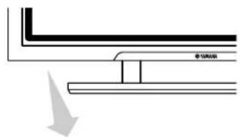
Main Unit
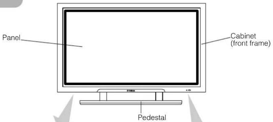
Front
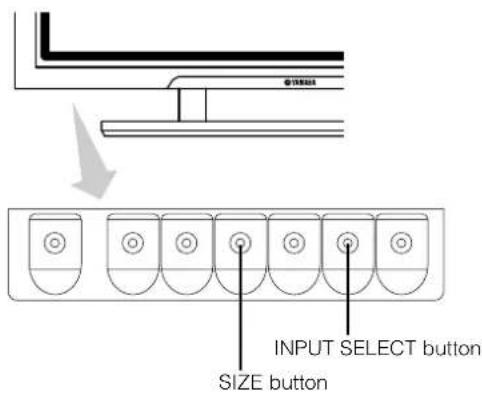
Control panel
- Adjustment buttons are located on the bottom.
The back cover is provided with indications to distinguish the adjustment buttons.
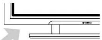
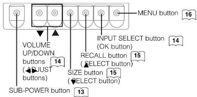
- ( ) indicates the function while the MENU is displayed on the screen.
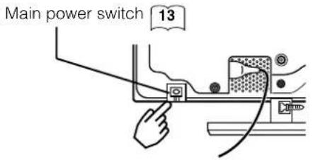
- The main power switch is located at the back, on the lower surface.
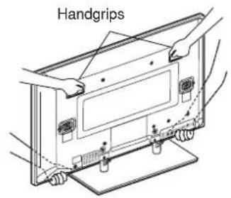
Caution when moving the main unit
- As this product is heavy, whenever it is moved, two people are required to transport it safely.
- Whenever the unit is moved it should be lifted forwards using the two handgrips at the back, and the unit should then be held at the base on both sides for stability.
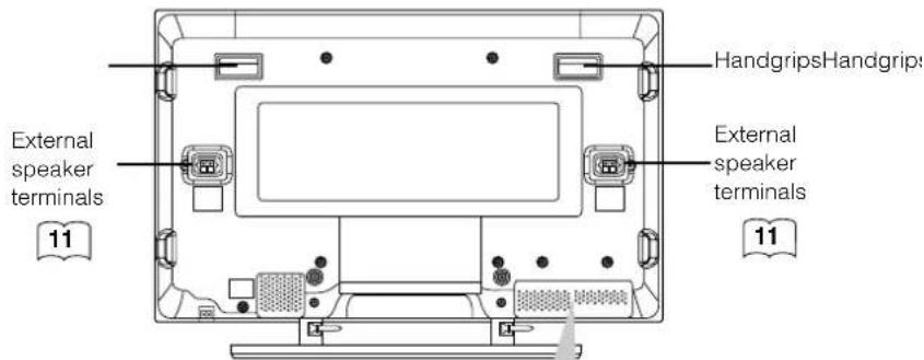
Rear
External device connection terminals
COMPONENT NAMES (continued)
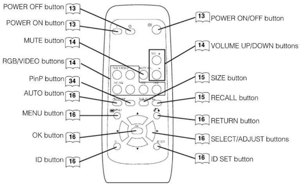
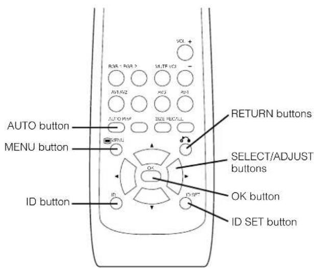
Remote control
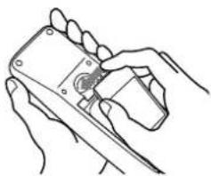
Loading Batteries
1. Open the battery cover.
- Slide back and remove the battery cover in the direction of the arrow.
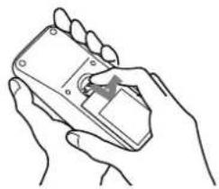
2. Load the batteries.
- Load the two Size AA batteries included, matching polarity markings on the batteries to those on the case.
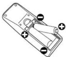
3. Close the battery cover.
- Replace the battery cover in the direction of the arrow and snap it back into place.
CAUTION
- Do not use new and old batteries together. The batteries could explode or leak, resulting in fires, physical injury, or stains.
- When loading batteries, observe their correct polarities as marked on the product. If loaded in the wrong direction, the batteries could explode or leak, resulting in fires, physical injury, or stains.
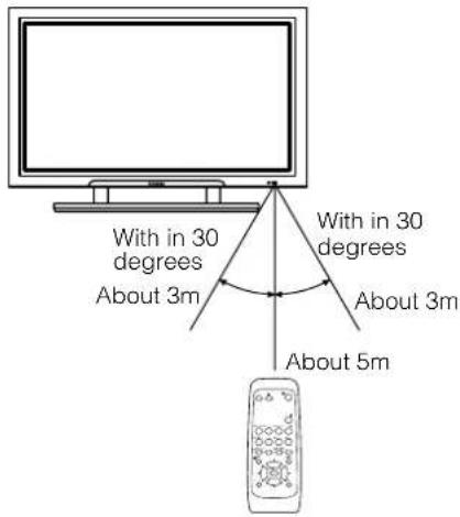
Handling the Remote Control
Use the remote control within about 5m from the front of the unit, within a 30 degree arc either side of the remote control sensor.
ATTENTION
- Do not drop exert undue force on the remote control.
- To avoid possible failures. Do not splash the remote control with water or put it on a wet object.
- It you do not intend to use the remote control for an extended period of time, remove the batteries from it.
- If the remote control begins to lack responsiveness, replace the batteries.
- Strong light such as direct sunlight impinging on the photoreceptor of the remote control can cause operational failure. Position this unit to avoid direct contact with such light.
INSTALLATION INSTRUCTIONS
Installation
- When installing the monitor, use the pedestal.
The pedestal has been used for the illustrations in this manual.
CAUTION
- Use one of the special mount units to install this product. A mount of insufficient strength or inadequate design can cause overturning or dropping and result in fire, electrical shock or injury. Please note that our company assumes absolutely no responsibility for personal injuries or property damage caused by use of other mount units or improper installation.
- Installation of the wall mount unit and ceiling mount unit can be dangerous, so do not attempt this work yourself. Ask your dealer to provide the name of a qualified installer.
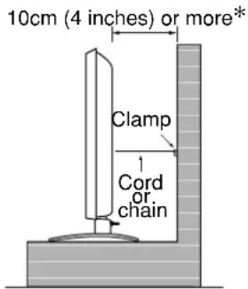
- In order to prevent an internal temperature increase, maintain a space of 10cm (4 inches: For a desktop setup) or more between the sides and other objects such as walls, etc., so that the ventilation holes are not blocked. ()
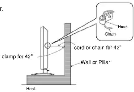
Anti-tumble measures
CAUTION
Have this unit mounted in a stable place. Take measures to prevent it from tumbling down to avoid possible physical injury.
Securing to a wall or pillar
Use a commercially available cord or chain, and a clamp to secure the set to a firm wall or pillar.
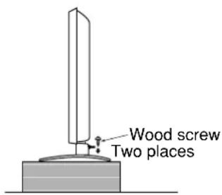
Securing to desktop
1) Using wood screws (two), fasten the set to the clamping screw holes on the rear of the pedestal as shown.
2) Using commercially available wood screws, secure the set firmly in position.
INSTALLATION INSTRUCTIONS(continued)
Read CAUTION: READ THIS BEFORE OPERATING YOUR UNIT. and PRECAUTIONS ( 3 to 7 ) carefully to ensure maximum safety before proceeding to these steps:
- Choose a safe level location to install the product.
- Install the monitor to have ready access to a power socket available.
- Make sure that the power switch of this device is turned off.
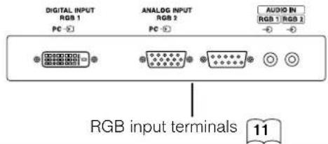
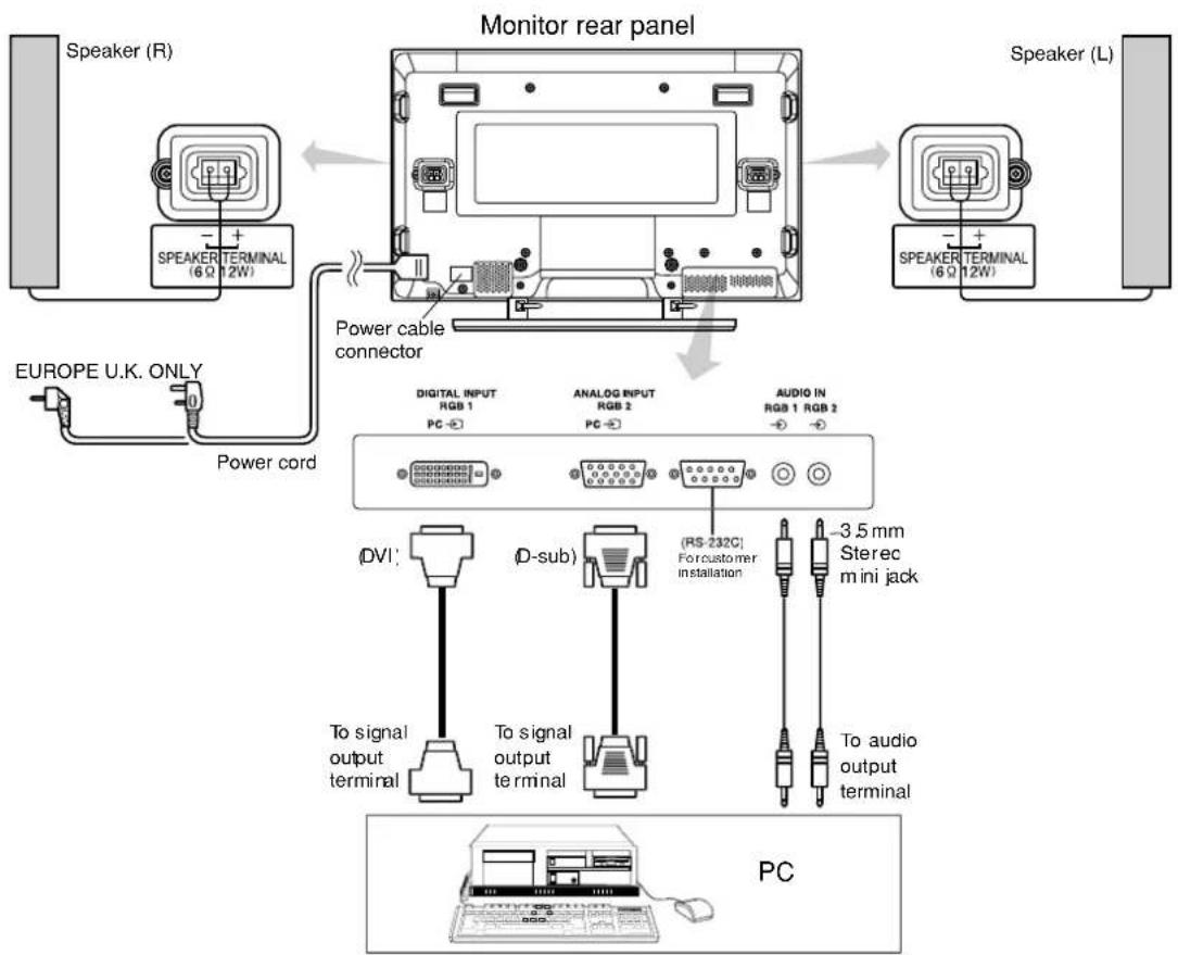
Connecting to a PC
(1) Make sure that the display signal of the personal computer to be used is compatible with the specifications of this device.
See "Product Specifications" concerning the specifications of this device. 27 29
(2) Make sure that the power switch of the personal computer is turned off.
(3) Connect the signal input terminal (RGB 1 or RGB 2) on the rear panel of this device to the display signal output terminal of the personal computer.
- Use a cable that fits the input terminal of this device and the output terminal of the personal computer.
- Depending on the type of personal computer being connected, the use of an optional conversion adapter or the adapter provided with the personal computer may be necessary in some cases. For details, refer to the instruction manual of the personal computer or ask the personal computer manufacturer or your local retail dealer.
INSTALLATION INSTRUCTIONS (continued)
Power Cord Connection
Connect the power cord after completing all other connections.
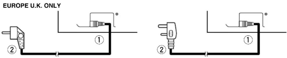
① Connect the power cord to this device.
② Connect the power cord plug to the power outlet.
(The type of plug is different from this drawing for some countries.)
CAUTION
- Use only the power cord provided.
- Do not use a power supply voltage other than that indicated (AC100-240V, 50/60Hz) as this may cause fire or electric shock.
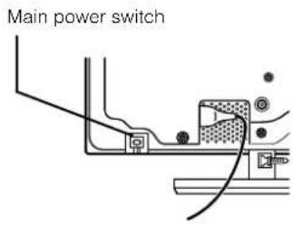
SUB-POWER button
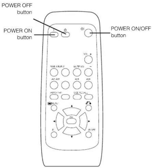
Turning Power On and Off
- To turn the monitor power on, press the main power switch on the monitor main unit to ON, and then press the SUB POWER button or the ON/OFF or ON button on the remote control.
-
To turn the monitor power off, press the SUB POWER button or the ON/OFF or OFF button on the remote control, and then set the main power switch on the monitor main unit to OFF.
-
During normal use, the main power switch is set in the ON position, and the monitor can then be turned ON/OFF using the SUB POWER button or the ON/OFF button on the remote control.
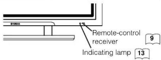
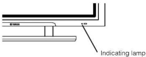
Indicating lamp
| Indicating lamp | Power status | Operating |
| Off Off | When the main power switch is set to OFF. | |
| Lights red | Off(standby) | When the main power switch is ON, and the OFF button on the remote control or the SUB POWER button on the underside of the front of the frame is OFF. |
| Lights green | On | When the main power switch is ON, and the ON button on the remote control or the SUB POWER button on the underside of the front of the frame is ON. |
| Lights orange | Off(Power Save) | When the main power switch is ON, and the ON button on the remote control or the SUB POWER button on the underside of the front of the frame is ON.However, the indicator also light orange when the unit is in POWER SAVE mode. |
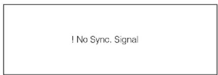
When the indicating lamp lights in orange or the message "No Sync. Signal", "Power Save" or "Invalid Scan Freq." appears on the screen, see "Power Save Mode" or "Symptoms that Appear to be
ATTENTION
- Avoid repeatedly turning the monitor on and off at short intervals. Failures might result from such operation.
- Turn off the main power switch if you do not plan to use the monitor for an extended period of time.
- If a power failure occurs while the main unit is running, it will be powered on upon recovery from the failure. Turn off the unit main power switch before you leave the area in which the main unit is located.
OPERATING INSTRUCTIONS (continued)
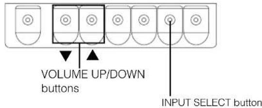
Input Switching
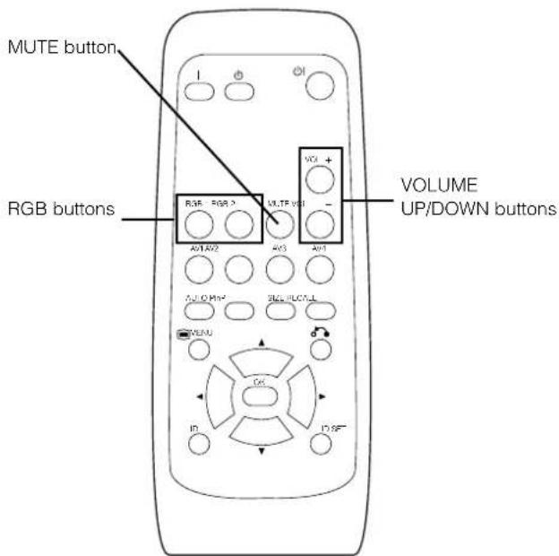
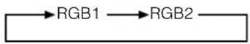
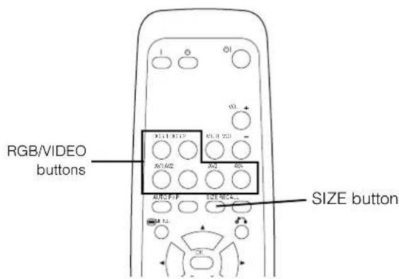
- Input can be switched by pressing the RGB1, RGB2, buttons of the remote control.
- Input can be switched in the sequence of RGB1 → RGB2 by pressing the INPUT SELECT button of the monitor.
Volume Adjustment
The volume can be adjusted by pressing the VOL+ and VOL- buttons of the remote control (or the and volume buttons of the monitor unit).
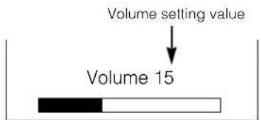
Adjustment status guide display
- When a button is pressed, the volume adjustment status guide will be displayed.
The volume will increase when the VOL+ (or ) button is pressed while the guide is being displayed.
The volume will decrease when the VOL- (or ) button is pressed while the guide is being displayed.
Audio Mute
The audio volume can be temporarily muted by pressing the MUTE button of the remote control.
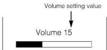
Adjustment status guide display (The display colour will change to magenta.)
- When a button is pressed, the volume adjustment status guide (magenta) will be displayed.
The volume setting can be lowered by pressing the VOL- button while the audio is mute.
- The muting can be cancelled by pressing the VOL+ button or MUTE button while the audio is mute.
When the MUTE button of the remote control is pressed again, the audio will be restored and the volume display (green) will appear.
OPERATING INSTRUCTIONS (continued)
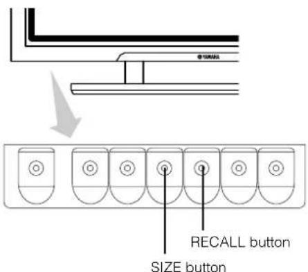
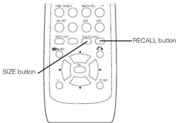
Size Switching
Each time the SIZE button of the remote control or the monitor is pressed, the screen display area will change in sequence and the status will be displayed at the bottom of the screen.
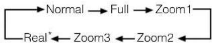
- Real mode gives an image of the same shape as it is displayed on a computer monitor. This mode is only available for VGA (640 X 480) and WVGA (864 X 480).
Display area selection diagram (RGB input)
| Resolution Ful | display Circular display | |||||
| Display Full | Normal Real Zoom1 | Zoom2 Zoom3 | ||||
| 640 X 480(VGA) | ||||||
| 800 X 600(SVGA) | ||||||
| 1024 X 768(XGA) | * VGA and W-VGA only | |||||
| 1280 X 1024(SXGA) | ||||||
| 1600 X 1200(UXGA) | ||||||
Processes such as compression (thinning) and expansion are performed for the above signal display. Because of this, there is a possibility that flicker may become noticeable on Zoom (1 ~ 3) depending on the display contents. If this occurs, turning the Vertical Filter On can reduce the flicker.
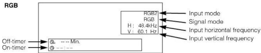
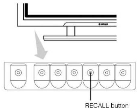
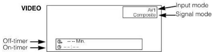
Input Signal Screen Display
The input signal status can be displayed on the screen by pressing the RECALL button of the remote control or the monitor.
The display will go out in approximately 6 seconds.
Automatic Adjustment of Screen Position and the Clock
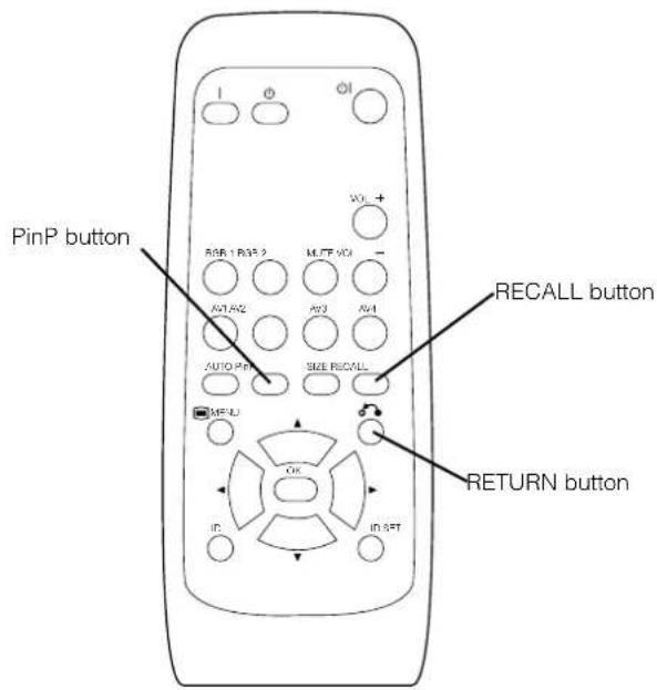
Adjustment of the screen to a position suitable for the PC signal and the clock adjustment can be performed automatically by pressing the AUTO button of the remote control.
CAUTION
Perform this adjustment for each input (RGB1 or RGB2) and for each signal.
- Depending on the signal, satisfactory adjustment may not be possible in some cases. In such cases, adjust by referring to the Setup Menu item.
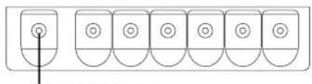
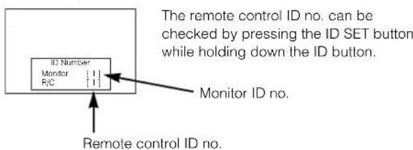
Independent Operation of Multiple Monitors (ID No)
Setting the ID No. of the remote control allows separate control of up to a maximum of seven monitors. Remote control ID No. 2 (initially ID no. 1) can be set by pressing the ID SET button for 2 sec. or more while holding down the ID button. The number will be incremented (2·s6 7 1 2) when this button pressed continuously.
The ID remote control is operated by pressing the various buttons while holding down the ID button; Operation is possible only when the remote control and monitor ID nos. are the same.
The remote control can be operated normally by pressing the various remote control buttons without holding down the ID button.
- Set the monitor using the ID No. of Function MENU. 19
Using the Menu Screen (On-screen display system)
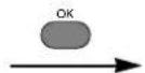
When the MENU button is pressed, the adjustment menu screen will be displayed; from there, PC signal adjustment and setting is possible by using the SELECT button, ADJUST button and OK button.
Refer to 17 - 21 concerning the adjustment items and the settings.
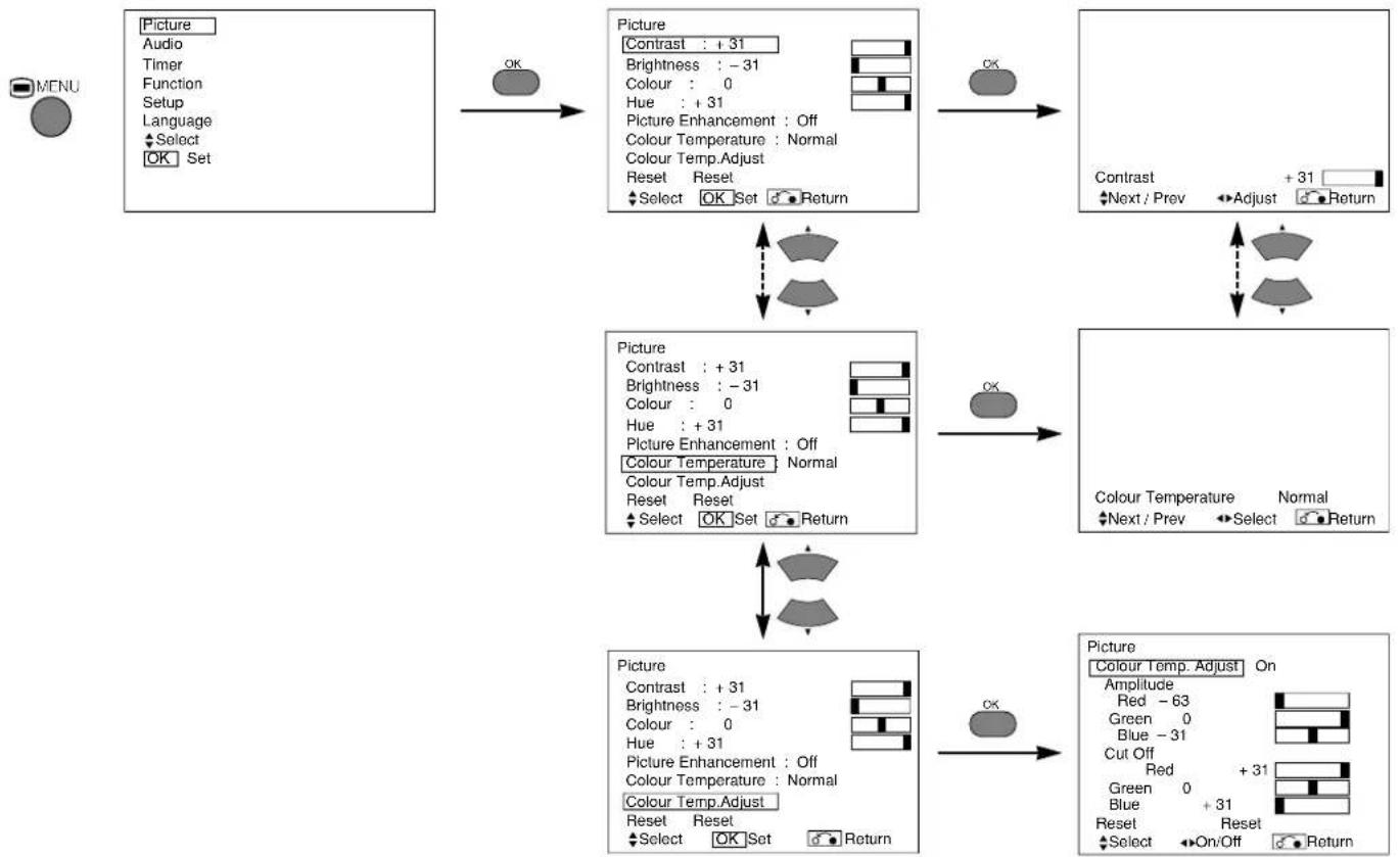
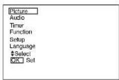
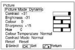
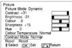
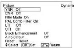
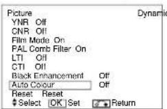
Example: Selecting the Picture screen
- Press the MENU button to display the Main Menu screen.

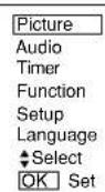
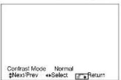
- Press the OK button to display the Picture Menu screen. (Use the and SELECT buttons to select other items.)

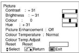
- Use the and SELECT buttons to select the item to be adjusted and then use the and ADJUST buttons to adjust (example: Contrast).
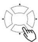
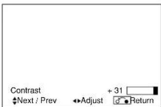
- Press the RETURN button to return to the previous screen.
- If there is no operation for a period of one minute, the Adjustment Menu screen will be closed automatically.
OPERATING INSTRUCTIONS (continued)
PICTURE MENU
| Selected characters | ← | → | Setup hint | |
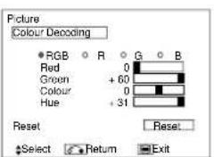
| Contrast | Narrows the gap between brightness and darkness. | Broaders the gap between brightness and darkness. | Adjust for maximum visibility to suit the ambient brightness. Adjust further till [+40] by pressing and holding cursor button at [+31]. The color for [+32] to [+40] numbers will change from white to magenta. This special mode is better for dark scenes. For brighter scene some parts of the picture might not be clear. We recommend to set at [+31]. "Panel Life" in the Function Menu should be set to Normal when Contrast setting is adjusted. | |
| Brightness | Black is subdued for increased overall darkness. | Black is set off for increased overall brightness. | Adjust to taste. | |
| Colour | Darkens colours. | Lightens colours. | Adjust to taste. | |
| Hue | Enhances red and weakens green. | Enhances green and weakens red. | This is not available for adjustment when receiving PAL/SECAM signal. In this case the character will be grayed out. Adjust for the most realistic skin colour. | |
| Picture Enhancement | Off←Low←Middle←High | Sets the clarity of small details to the desired level. | ||
| Colour Temperature | Cool←Normal←Warm←Black/White | Normally set to Normal. | ||
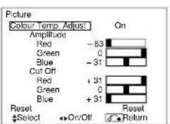
| Colour Temp. Adjustment | Off←On← | Turn On when you wish to change colour temperature to suit user preferences. | ||
| Amplitude | Red | Brighter scenes are decreased in reddish colour. | Brighter scenes are increased in reddish colour. | Adjust colour temperature to suit user preference. These settings are independently stored in each of the 4 Colour Temperature modes. |
| Green | Brighter scenes are decreased in greenish colour. | Brighter scenes are increased in greenish colour. | ||
| Blue | Brighter scenes are decreased in bluish colour. | Brighter scenes are increased in bluish colour. | ||
| Cut Off | Red | Dark scenes are decreased in reddish colour. | Dark scenes are increased in reddish colour. | |
| Green | Dark scenes are decreased in greenish colour. | Dark scenes are increased in greenish colour. | ||
| Blue | Dark scenes are decreased in bluish colour. | Dark scenes are increased in bluish colour. | ||
| Reset | (Selects the Reset mode) | The original factory settings for the items of this Menu page can be restored by pressing the OK button. | ||
OPERATING INSTRUCTIONS (continued)
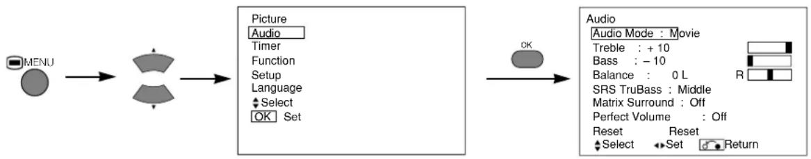
AUDIO MENU
| Selected characters Setup hint | ► | ||
| Audio Mode | Movie → Music → Speech → Favourite ← | Movie: This selects the audio mode suitable for Movies. Music: This selects the audio mode suitable for Music. Speech: This selects the audio mode suitable for News, Talk show etc. Favourite: This mode should be adjusted to suit your preference. | |
| Treble | Suppresses treble. Enhances treble. Adjust to taste. | ||
| Bass | Suppresses bass. Enhances bass. Adjust to taste. | ||
| Balance | Suppresses right-side sound. Suppresses left-side sound. Adjust to taste. | ||
| SRS TruBass | Off←Low←Middle←High← | SRS TruBass takes advance of the ability of the human ear to distinguish between two different tones. By using this ability, TruBass gives enhanced bass sound that otherwise would not be heard. Adjust it depending on the user's preference. | |
| Matrix Surround | Off←On← | This features the spacious sound effects of a stadium. | |
| Perfect Volume | Off←On← | This will automatically adjust volume so each channel and input has the same average volume level. | |
| Reset | (Selects the Reset mode) | The original factory settings for the items of this Menu page can be restored by pressing the OK button. | |
TIMER MENU

| Selected characters Setup hint | ▲ | ||
| Off Timer | --Min.←30Min.←60Min.→120Min.←90Min.← | This function automatically sets the power to standby status when the indicated time period has elapsed. | |
| On Timer | --(: --) hours | (-:)-- minutes | This automatically sets the power from standby to ON when the indicated time period has elapsed. The settable time is 00:00~11:59. Input the required time by ▼▲ SELECT buttons on the remote control. |
OPERATING INSTRUCTIONS (continued)
FUNCTION MENU
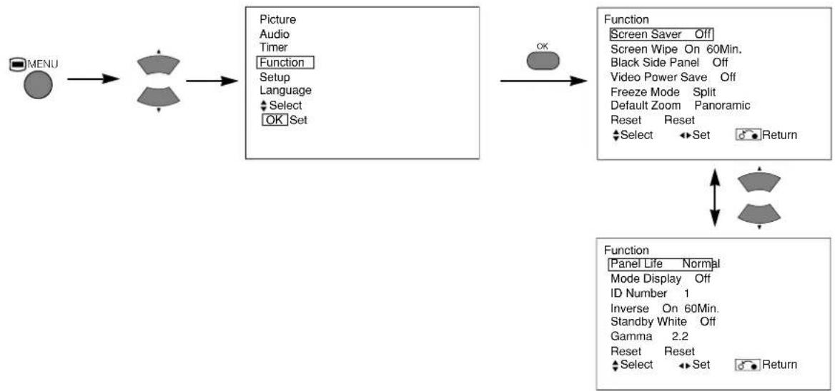
| Selected characters | ← | → | Setup hint |
| Screen Saver | →Off←5Min.←10Min.←60Min.←40Min.←20Min.← | This moves the picture around the screen in small amounts, at set intervals, to reduce the panel image retention. Image retention occurs when stationary objects, such as screen logos, leave a slight image visible after they should have disappeared. | |
| Screen Wipe | On | 60Min. | This is used to reduce the panel image retention that can occur with stationary pictures by displaying a completely white screen. Select On (continuous operation) or 60 Min. (time limit operation) and press the OK button. Press the MENU or RETURN button on the remote control to return to normal viewing. |
| Black Side Panel | →Off←On← | This turns the gray sidebars On/Off when watching normal mode screen size area. It is always set to Off when the monitor is powered On. It is recommended to set Black Side Panel to off to reduce the panel image retention. | |
| Video Power Save | Optional (grayed out) | ||
| Freeze Mode | Optional (grayed out) | ||
| Default Zoom | Optional (grayed out) | ||
| Reset | (Selects the Reset mode) | The original factory settings for the items of this Menu page can be restored by pressing the OK button. | |
| Panel Life | Normal←Extend 1←Extend 2 | This function suppresses the contrast of the screen regardless of the Contrast setting in the Picture Menu. By this control, power consumption can be reduced or degradation of a panel can be mitigated. The order of power consumption is Extend 2 < Extend 1 < Normal. If the Contrast setting is changed when this item is set to Extend 1 or 2, it will be changed to Normal automatically. | |
| Mode Display | →Off←On← | This functions displays the Input Signal Screen Display every time the input mode and signal mode are changed. Set to OFF if the Input Signal Screen Display is not needed when switching signals. | |
| ID Number | 1←2←3←47←6←5 | Assigns ID nos. to the monitors so that they can be controlled individually (up to 7 monitors can be controlled). | |
| Inverse | On | 60Min. | This function changes each level of RGB signal invert to reduce the panel image retention. When this function is required, select On (continuous operation) or 60Min. (time limit operation) and press the OK button. And press the Menu or Return button to exit. |
| Standby White | →Off←15Min.←30Min.→120Min.←60Min. | This function is also provided to prevent image retention. If time is set for this item, the screen changes into a white pattern when the monitor enters power save mode, and continues for the period of setting time. | |
| Gamma | →2.2←→2.8 | Normally set to 2.2. | |
OPERATING INSTRUCTIONS (continued)
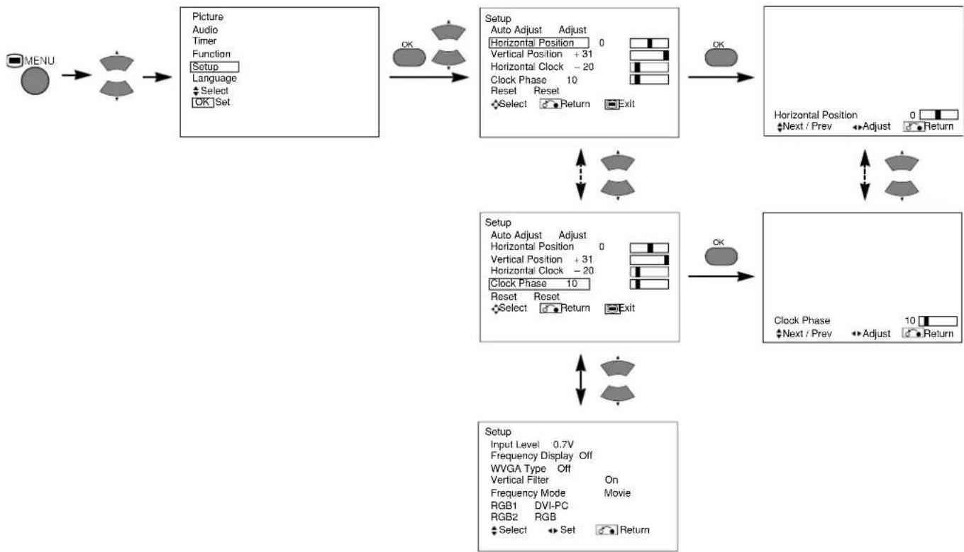
SETUP MENU
| Selected characters Setup hint | |||
| Auto Adjust* | ( Menu) (Adjust) | Press the OK button to start automatic regulation. | Horizontal Position, Vertical Position, Horizontal Clock and Clock Phase are adjusted automatically. |
| Horizontal Position | Moves the horizontal position to left. | Moves the horizontal position to right. | Adjust the left-side display position. (This function is only for RGB2. It is not available (grayed out) for RGB1.) |
| Vertical Position | Moves down the vertical position. | Moves up the vertical position. | Adjust the vertical display position. (This function is only for RGB2. It is not available (grayed out) for RGB1.) |
| Horizontal Clock | Reduces the dot clock frequency (shrinks the right side). | Increases the dot clock frequency (expands the right side). | Adjust for maximum character clarity. (This function is only for RGB2. It is not available (grayed out) for RGB1.) |
| Clock Phase | Slows the dot clock phase (shifts slightly to left). | Advances the dot clock phase (shifts slightly to right). | Adjust for clear character visibility. (This function is only for RGB2. It is not available (grayed out) for RGB1.) |
| Reset | (Selects the Reset mode) | The original factory settings for the items of this Menu page can be restored by pressing the OK button. (This is effective only for RGB2.) | |
| Input Level | 0.7V←→1.0V← | Normally set to 0.7 V. If white is found to spread across the screen, set to 1.0 V. (This is effective only for RGB2.) | |
| Frequency Display | Off←→On← | Set this to Off if the frequency information of the Input Signal Screen Display is not required. | |
| WVGA Type | Off←→On← | This is only available for W-VGA signal. When it is set to On, the display area modecan be selected Full or Real. | |
| Vertical Filter | Off←→On← | Turn On when concerned about screen flicker. | |
| Frequency Mode | Movie←→PC← | Set to Movie when viewing moving images on a personal computer. | |
| RGB1 | Optional (grayed out) | ||
| RGB2 | Optional (grayed out) | ||
- Depending on the type of signal displayed, displays may not be optimized through automatic adjustment. Adjust manually to optimize them.
OPERATING INSTRUCTIONS (continued)
LANGUAGE MENU
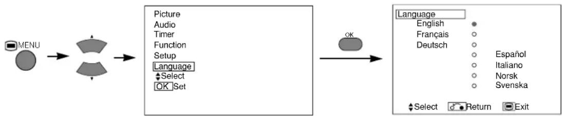
Select a language using the SELECT buttons and press the OK button.
OTHER FEATURES
Automatic Store
Approximately 1 sec. after adjustment is completed, the adjustments will be recorded as shown in the table below.
| Menu Display Registration condition | ||
| Picture | Contrast | For every input function, 1 setting is registered. |
| Brightness | ||
| Colour | ||
| Hue | ||
| Picture Enhancement | ||
| Colour temperature | ||
| Colour Temp. Adjust | ||
| R Amplitude | For every Colour Temperature, 1 setting is registered. | |
| G Amplitude | ||
| B Amplitude | ||
| R Cut Off | ||
| G Cut Off | ||
| B Cut Off | ||
| Audio | Audio Mode 1 setting | is registered. |
| Treble | For every Audio Mode, 1 setting is registered. | |
| Bass | ||
| Balance 1 setting is registered. | ||
| SRS TruBass | For every Audio Mode, 1 setting is registered. | |
| Matrix Surround | ||
| Perfect Volume | ||
| Menu Display Registration condition | |
| Function | Screen Saver 1 setting is registered. |
| Screen Wipe (not registered) | |
| Black Side Panel (not registered) | |
| Panel Life 1 setting is registered. | |
| Mode Display | |
| ID Number | |
| Inverse | |
| Standby White | |
| Gamma | |
| Setup | Auto Adjust (not registered) |
| Horizontal Position For every signal Mode, 1 setting is registered. (Only for RGB2) | |
| Vertical Position | |
| Horizontal Clock | |
| Clock Phase | |
| Input Level 1 setting is registered. | |
| Frequency Display | |
| WVGA Type | |
| Vertical Filter | |
| Frequency Mode | |
| Language | |
The previously recorded items will be lost.
- The signal mode can be identified by the horizontal/vertical sync frequency and the sync signal polarity. Different signals for which all the elements are the same or similar will be handled as the same signal.
OTHER FEATURES (continued)
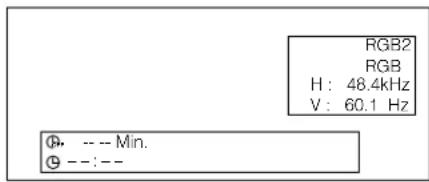
Signal Check
Changes in the signal status are displayed on the screen as they arise.
| Status Display | Action | |
| When Mode Display is set to ON, the input signal is switched or when the RECALL button is pressed. | A guide is displayed for the input terminal and the horizontal and vertical sync frequency. | |
| When the sync signal is no longer detected. | ·A guide displays No Sync. Signal, and Power Save (for approx. 5 sec.) ·When the condition continues and the sync signal cannot be detected, the indicator lamp of the power source changes in orange and the mode switches to power save mode. | Recheck the personal computer power switch status and the connection status. |
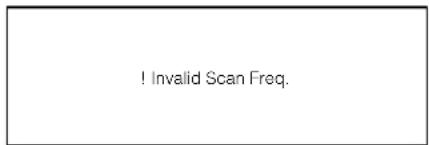
| When the input signal does not match the monitor specifications or is in an unstable state. | "Invalid Scan Freq" appears on the display panel. | Recheck the input signal specifications. |
RGB
Power Save Mode
When the RGB, RGB2 input is selected
- When this unit is connected to a VESA DPMS computer, the Power Save (Off) mode can be set to be activated automatically when the computer is not being used to reduce power consumption by this unit.
| RGB sync signal | Horizontal Yes | No Yes No | |||
| Vertical Yes | Yes No No | ||||
| PC signal Active (normal) | display) Blank (no display) | ||||
| Operation mode | On | Off | |||
| Indicating lamp | Lights green | Lights orange | |||
| Power consumption 365W (42") | 3W or less (RGB1)1W or less (RGB2 ; 100V≤AC≤120V)3W or less (RGB2 ; 120V<AC≤240V) | ||||
Returning to operating status
- Operate the personal computer, or press either the INPUT SELECT button of the main unit or the RGB1/RGB2 buttons of the remote control to return the unit to power on mode.
IMAGE RETENTION OF PLASMA DISPLAY PANEL
There are different characteristics that result in panel image retention depending on how the plasma monitor is used. Situations and effective usage methods related to ghosting are provided below.
Image retention characteristics of a plasma display panel
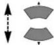
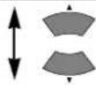
The image retention phenomenon of a plasma display panel occurs due to partial phosphor degradation arising from partial character and figure display.
For example, when the character image as shown in Fig. A at the right is continuously displayed for a long period of time, the only part of the phosphor (Red,Green, Blue) that will degrade will be the colour of the applicable character display portion. Consequently, when a white image is displayed on the entire screen as shown in Fig. a, the character marks displayed up to that time will become a colour difference visible to the eye, but the phosphor will never burn.

[Fig. A] [Fig. a]
The degree of image retention is proportional to the brightness of the characters and figures displayed as well as the display time.
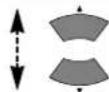
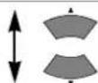
- The tendency of the phosphor is to degrade more the brighter the characters and figures are displayed. When images of figures with different levels of brightness, as shown in Fig. B, are continuously displayed for a long period of time, it becomes easier for image marks at locations when the brighter figures are displayed to be noticeable.

[Fig. B] [Fig. b]
The image retention images in this document are exaggerated for the purpose of explanation. The actual manner in which the image retention is seen differs depending on the operation time and brightness.
Methods to Reduce the Occurrence of Image Retention
- Lower the Contrast and Brightness settings of the plasma display panel as much as possible.
A function is provided in the display that allows you to control the brightness of the screen to reduce degradation of the panel. Using this function makes it possible to reduce image retention.
Refer to Panel Life (Extend 1.or Extend 2 shown on 19
- Set the plasma monitor to an "Screen Wipe" or "Inverse" display.
The occurrence of image retention when displaying images of identical patterns, such as static images, for long periods of time can be reduced by displaying a reversed colour or completely white screen for about 1 ~ 2 hours after terminating the display.
(Settings can be made using Screen Wipe and Inverse of Function MENU shown on 19)
- Using in combination with moving images
Since the degradation of the fluorescent material progresses comparatively uniformly for moving images, the occurrence of partial image retention can be controlled. We recommend using the plasma monitor in combination with moving images such as those of DVD.
Please be careful since image retention will occur if display is left in a two screen display state for a long period of time.
Television broadcasts include images displayed for long periods of time in which the left and right or top and bottom of the image are cut and broadcast station name or time are displayed for a long period of time at the same portion of the screen. Image retention in these portions can be expected to occur, so please be aware.
NOTES
About screen defects
- High precision technology is used in the making of plasma display panel but there may be dark spots (points that do not illuminate) and bright spots (points that are too bright) in some cases. These do not indicate a malfunction.
About residual images
- In some cases, residual images may remain after the short-term display of still images and another image is displayed, but these will disappear and return to normalcy. This is not a malfunction.
About the panel screen
- Plasma display panels display images by means of electrical discharges inside the panel. Because of this, the temperature of the panel surface may rise in some cases. Also, plasma display panels are made of finely processed glass. A reinforced glass filter is installed over the panel surface but avoid strong impact because there is still danger of glass breakage.
Symptoms That Appear to be Failures
Make the checks suggested below depending on the symptoms observed. If the symptoms remain uncorrected, contact your dealer.
CAUTION
Customer servicing can be hazardous.
| Symptom | Point to check | See page |
| ·No picture with the power-indicating lamp off. | ·Check the way the power cable is connected. ·Press the power switch. | 12 13 |
| ·The message "No Sync. Signal" or "Power Save" is displayed. ·No picture, with the power indicating lamp lit orange. | No sync signal is detected. ·Check the way the signal cable is connected. ·Make sure that the switch of the computer, imaging equipment, etc., is turned on. ·Make sure the computer is not in the power-saving mode. ·Check to see if the input selection matches the connection terminal. | 11 |
| ·The message "Invalid Scan Freq." is displayed. ·Invalid Scan Freq. | An input signal is not received normally. ·Check to see if the input signal matches the monitor specifications. ·Check the way the signal cable is connected. | 11 28 29 |
| ·The power indicating lamp is lit normally but no picture displays. | ·Check the contrast and brightness settings (adjust them for higher contrast and brightness). ·Check the way the signal cable is connected. | 17 11 |
| ·The display image appears flowing slantwise. ·Text displayed across the screen appears vertically streaked, with the characters in vertical columns blurred. | ·Adjust the dot clock frequency and phase. (Adjust the dot clock frequency first, the dot clock phase next.) (RGB input) | 20 26 |
| ·Text displayed across the screen appears blurred. ·A fine pattern flickers when displayed on the screen. | ·Adjust the dot clock phase for the clearest viewing. (RGB input) | 20 26 |
| ·The remote control does not work. | ·Check to see if the batteries are loaded in the remote control in opposite direction. ·Check to see if the batteries in the remote control are OK. ·Check if the setting of remote control ID no. is correct. | 9 16 |
Symptoms That Appear to be Failures (continued)
| Symptom Point to check See page | ||
| The temperature of the display panel surface is high. | Plasma display panel is lighting the phosphors in the display panel by the discharge of internal radiation. In some cases, this may cause the temperature of the panel surface to increase. Please note that this is not a malfunction. | - |
| There are points (*) on the screen that differ in colour from the periphery of the screen. *Points that do not light, points with brightness different from that of the periphery, points with color different from that of the periphery, etc. | High-precision technology is used to manufacture the plasma display panel. However in some cases, there are minor defects in some parts of the screen. Please note that this is not a malfunction. | - |
| Vertical stripes appear, depending on the screen contents. | The plasma display panel is lighting the phosphors by the discharge of internal radiation. Depending on the screen contents, in rare cases this may cause vertical stripes to appear because of failure to light. Please note that this is not a malfunction. | - |
| Coarse horizontal stripes appear in FULL display. | Adjusting the Clock Phase will reduce the horizontal stripes. (RGB input) | 20 |
| Flickering in the form of horizontal lines oscillating up and down. (PC INPUT MODE only) | If the direct frequency from the computer is below 85Hz, try a higher frequency (upper limit 85Hz). There may be a slight attenuation of the current image. Try turning the Vertical Filter On. For this case however, the vertical resolution will drop. | 20 |
| The fan motor is noisy. (Fan application model only) | Use the fan that controls the temperature in the main body to lower the temperature of this unit. If the ambient air temperature increases, the fan will start, the RPMs will increase and motor noise will grow louder. This is not a malfunction though. | - |
| The top of the monitor heats up. | When used for long periods of time, the top of the monitor may heat up. This is not a malfunction. | - |
| Text characters are displayed with varying thicknesses. | The thicknesses of characters and lines may vary if images with a vertical resolution greater than 512 lines are displayed; however, this is not a malfunction. | - |
Actions to Correct Abnormal Displays (continued)
Depending on the kind of system equipment used, images may not be displayed normally. In this case, make the adjustments suggested below. (only for RGB2)
| Symptom 1 | Text displayed across the screen appears vertically streaked, with some characters blurred (figure 1). The display image appears flowing (figure 2) (RGB input). |
| Example | Figure 1 Vertical streaks Before adjustment Some characters are blurred. ABC ABC After adjustment All characters appear crisp now. ABC ABC After adjustment All characters are blurred. |
| Adjustment procedure | 1) Press the AUTO button on the remote control. |
| When adjustment is not possible with Auto Adjust 2) Press the MENU button. The Main Menu will be displayed. 3) Press the SELECT button and select Setup. 4) Press the OK button. The Setup Menu will be displayed. 5) Press the SELECT button and select Horizontal Clock. (Display fine patterns as characters or a vertical striped pattern over the entire screen during Horizontal Clock adjustment.) 6) Press the for ADJUST buttons and search for clear characters over the entire screen. 7) Perform adjustment for symptom 2 below, when the characters are blurred on the entire screen. |
The display image may be momentarily disturbed during clock adjustment but this is not a failure.
| Symptom 2 | Text displayed across the screen appears blurred in its entirety (figure 2). A fine pattern flickers when displayed on the screen (figure 3). | |
| Example | Figure 2 | Before adjustment ABC After adjustment ABC |
| Adjustment procedure | 1) Press the AUTO button on the remote control. | |
| When adjustment is not possible with Auto Adjust 2) Press the MENU button. The Main Menu will be displayed. 3) Press the SELECT button and select Setup. 4) Press the OK button. The Setup Menu will be displayed. 5) Press the SELECT button and select Clock Phase. (Display fine patterns as characters or a vertical striped pattern over the entire screen during Clock Phase adjustment.) | ||
| 6) Press or ADJUST buttons to make the text appear clean across the screen. | 6) Press or ADJUST buttons to make the text appear without flickering. | |
PRODUCT SPECIFICATIONS
Product specifications and designs are subject to change without notice.
| Panel | Display dimensions | Approx. 42 inches (922 (H) x 522 (V) mm, diagonal 1059mm) |
| Resolution | 1024 (H) x 1024 (V) pixels | |
| Net dimensions (excluding pedestal) | 1030 (W) x 636 (H) x 91 (D) mm | |
| Net weight (excluding pedestal) | 34.9kg | |
| Ambient conditions | Temperature | Operating: 5°C to 35°C, Storage: 0°C to 40°C |
| Relative humidity | Operating: 20% to 80%, Storage: 20% to 90% (non-condensing) | |
| Power supply | AC100 - 240V, 50/60Hz | |
| Power consumption/at standby | 365W / <3W | |
| Audio output | 12W + 12W (6Ω) | |
| (RGB Input) | ||
| Input signals | Input terminals | RGB1 DVI input terminal (DVI-D) RGB1 audio input terminal (3.5mm Stereo Mini Jack) RGB2 analog RGB input terminal (D-sub 15-pin) RGB2 audio input terminal (3.5mm Stereo Mini Jack) |
| Video signals | 0.7 V/1.0 Vp-p, analog RGB (Recommended Signal) | |
| Sync signals | H/V separate, TTL level [2KΩ] H/V composite, TTL level [2KΩ] Sync on green, 0.3 Vp-p [75Ω] | |
| Recommended signal | 43 modes 28 29 | |
- The monitor takes at least 30 minutes to attain optimal picture quality.
Signal Input
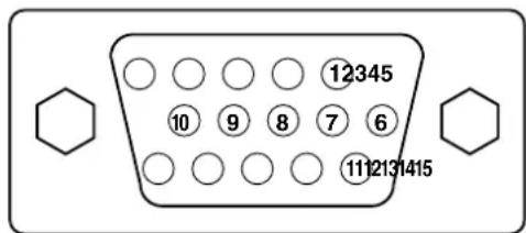
RGB terminal (D-sub 15-pin connector)
| Pin | Input signal |
| 1 | R |
| 2 G or sync on green | |
| 3 | B |
| 4 No connection | |
| 5 No connection | |
| 6 R.GND | |
| 7 G.GND | |
| 8 B.GND | |
| 9 No connection | |
| 10 GND | |
| 11 No connection | |
| 12 [SDA] | |
| 13 H. sync or H/V composite sync | |
| 14 V-sync. [V.CLK] | |
| 15 [SCL] | |
- When different kinds of input signals are simultaneously input to the monitor via a graphics board or the like, the monitor will automatically select the signals in the following priority order:
| Sync signal type Priority | |
| H/V separate sync. 1 | |
| H/V composite sync. 2 | |
| sync.on Green * 3 |
*Even in the case of the recommended signals shown on the following page, there may be instances when correct display is not possible. In this case, use H/V separate sync, H/V composite sync.
Signal Input (continued)
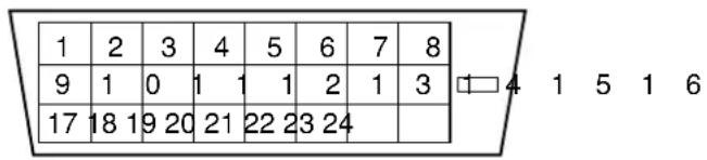
DVI terminal (DVI-D)
| Pin | Input signal | Pin | Input signal |
| 1 | T.M.D.S. Data2- | 14 | +5V Power |
| 2 | T.M.D.S. Data2+ | 15 | Ground (for+5V) |
| 3 | T.M.D.S. Data2/4 Shield | 16 | Hot Plug Detect |
| 4 | T.M.D.S. Data4- | 17 | T.M.D.S. Data0- |
| 5 | T.M.D.S. Data4+ | 18 | T.M.D.S. Data0+ |
| 6 | DDC Clock | 19 | T.M.D.S. Data0/5 Shield |
| 7 | DDC Data | 20 | T.M.D.S. Data5- |
| 8 | No Connect | 21 | T.M.D.S. Data5+ |
| 9 | T.M.D.S. Data1- | 22 | T.M.D.S. Clock Shield |
| 10 | T.M.D.S. Data1+ | 23 | T.M.D.S. Clock+ |
| 11 | T.M.D.S. Data1/3 Shield | 24 | T.M.D.S. Clock- |
| 12 | T.M.D.S. Data3- | Frame | GND |
| 13 | T.M.D.S. Data3+ |
Recommended Signal List
With Digital RGB signal input (RGB1 input)
| No. | Signalmodus | Horizontal frequency (kHz) | Dot clock frequency (MHz) | Remarks | ||
| Signal Name | Resolution | Vertical frequency (Hz) | ||||
| 1 | VGA | 640 X 400 | 70.08 | 31.47 | 25.18 | |
| 2 | 640 X 480 | 59.94 | 31.47 | 25.18 | ||
| 3 | W-VGA | 864 X 480 | 59.94 | 31.47 | 34.24 | WVGA type:On |
| 4 | VESA | 640 X 480 | 72.81 | 37.86 | 31.50 | |
| 5 | 640 X 480 | 75.00 | 37.50 | 31.50 | ||
| 6 | 640 X 480 | 85.01 | 43.27 | 36.00 | ||
| 7 | 800 X 600 | 56.25 | 35.16 | 36.00 | ||
| 8 | 800 X 600 | 60.32 | 37.88 | 40.00 | ||
| 9 | 800 X 600 | 72.19 | 48.08 | 50.00 | ||
| 10 | 800 X 600 | 75.00 | 46.88 | 49.50 | ||
| 11 | 800 X 600 | 85.06 | 53.67 | 56.25 | ||
| 12 | 1024 X 768 | 60.00 | 48.36 | 65.00 | ||
| 13 | 1024 X 768 | 70.07 | 56.48 | 75.00 | ||
| 14 | 1024 X 768 | 75.03 | 60.02 | 78.75 | ||
- Make sure that the signal of the equipment to be connected is compatible with the specifications on this list.
Recommended Signal List (continued)
With Analog RGB signal input (RGB2 input)
| No. | Signal mode | Horizontal frequency (kHz) | Dot clock frequency (MHz) | Remarks | ||
| Signal Name | Resolution | Vertical frequency (Hz) | ||||
| 1 | VGA | 640 X 400 70.0 | 8 31.47 25.18 | |||
| 2 | 640 X 480 59.94 3 | 1.47 25.18 | ||||
| 3 | VGA 864 X 480 | 59.94 31.47 34.24 | W VGA type:On | |||
| 4 | 640 X 480 72.8 | 1 37.86 31.50 | ||||
| 5 | 640 X 480 75.00 3 | 7.50 31.50 | ||||
| 6 | 640 X 480 85.01 4 | 8.27 36.00 | ||||
| 7 | 800 X 600 56.25 3 | 5.16 36.00 | ||||
| 8 | 800 X 600 60.32 3 | 7.88 40.00 | ||||
| 9 | 800 X 600 72.19 4 | 8.08 50.00 | ||||
| 10 | 800 X 600 75.00 4 | 6.88 49.50 | ||||
| 11 | 800 X 600 85.06 5 | 8.67 56.25 | ||||
| 12 | 1024 X 768 60.00 | 48.36 65.00 | ||||
| 13 | 1024 X V88A70.07 | 56.48 75.00 | ||||
| 14 | 1024 X 768 75.03 | 60.02 78.75 | ||||
| 15 | 1024 X 768 85.00 | 68.68 94.50 | ||||
| 16 | 1152 X 864 75.00 | 67.50 108.00 | ||||
| 17 | 1280 X 1024 60.02 | 63.98 108.00 | ||||
| 18 | 1280 X 1024 75.03 | 79.98 135.00 | ||||
| 19 | 1280 X 1024 85.02 | 91.15 157.50 | ||||
| 20 | 1300 X 1200 60.00 | 75.00 162.00 | ||||
| 21 | 1300 X 1200 75.00 | 93.75 202.50 | ||||
| 22 | 1300 X 1200 85.00 | 106.25 229.50 | ||||
| 23 | 640 X 480 66.67 | 35.00 30.24 | ||||
| 24 | 32 X 624 74.55 4 Macintosh | 9.72 57.28 | ||||
| 25 | 1024 X 768 74.93 | 60.24 80.00 | ||||
| 26 | 152 X 870 75.06 | 68.68 100.00 | ||||
| 27 | W-XGA | 1280 X 768 59.833 | 47.986 81.00 | |||
| 28 | 1280 X 768 69.997 | 56.137 94.760 | ||||
The type of video board or connecting cable used may not allow for correct display adjustment of Horizontal Position, Vertical Position, Horizontal Clock and Clock Phase.
The monitor may fail to display an animation image correctly when a signal having a vertical frequency of 85Hz or higher is input to it.
The monitor differentiates signal modes according to the horizontal and vertical frequencies and the horizontal and vertical sync signal polarities. Note that different signals having all these elements alike may be handled as the same signal.
- Displaying images with more than 512 lines of vertical resolution at Full display (compressed display) can result in the interpolation of stripes.
SUPPLEMENT
Optional Video Unit Function
Additional functions when the optional video unit is installed are as follows: (3142)
INSTALLATION INSTRUCTIONS
Connecting to a Video Imaging Device
(1) Make sure that the power switch of the monitor is turned off.
(2) Make sure that the power switch of the imaging device is turned off.
(3) Use a commercially available cable and connector to connect the signal input terminal on the rear panel of this device and the signal output terminal of the imaging device.
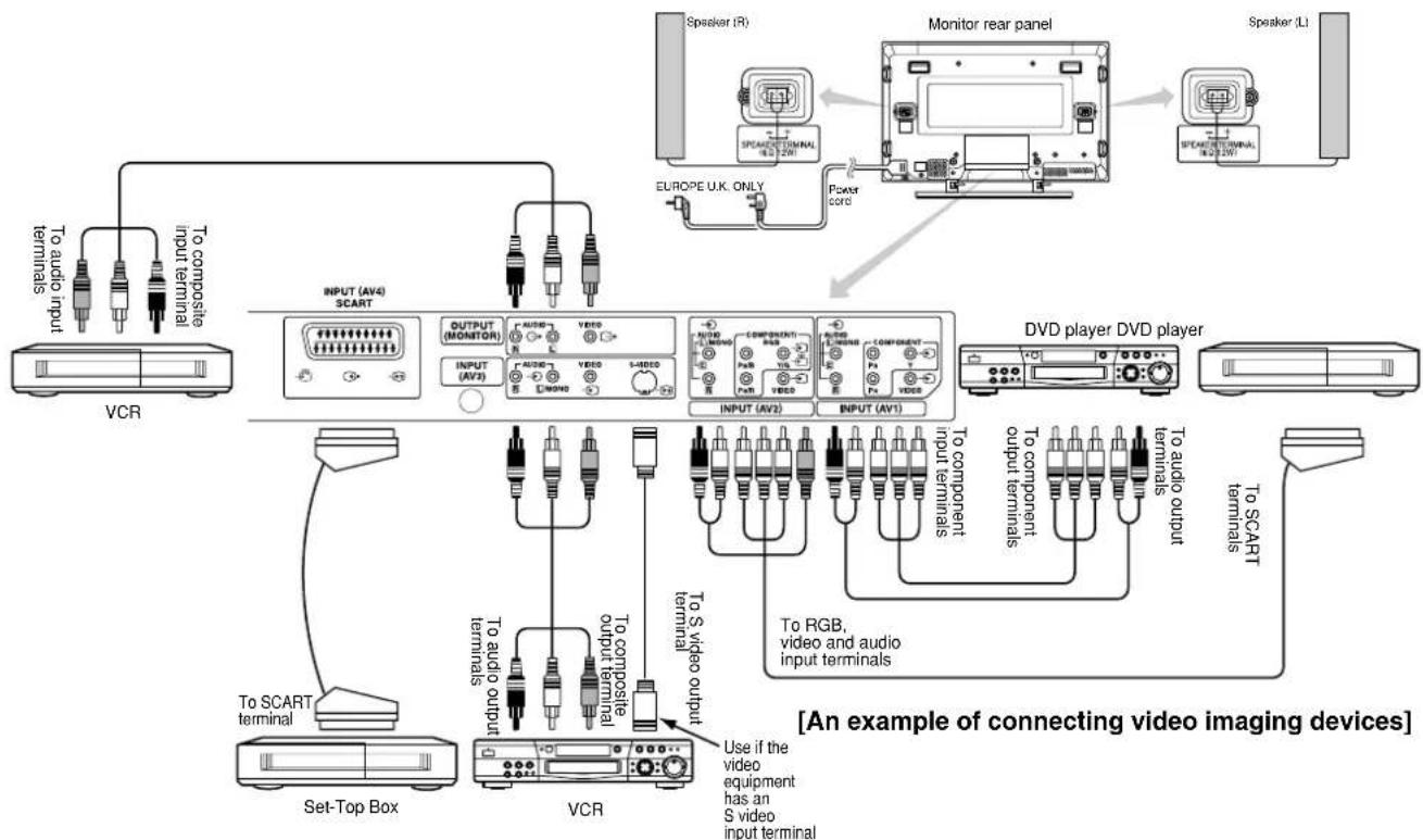
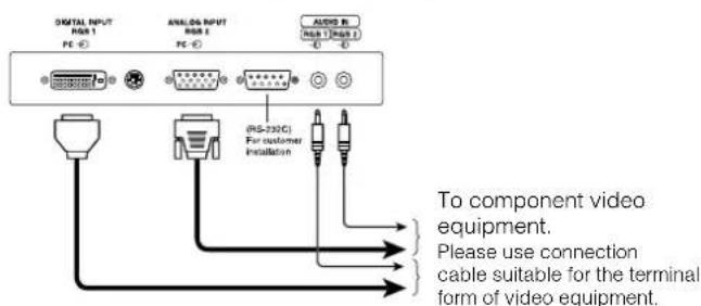
DVI-STB and RGB component setup
- If video equipment with an S video output terminal is used, connection with S video cable is recommended to provide finer video quality. (If the S video input terminal and the video input terminal of AV3 connect to the monitor at the same time, S video input would govern.)
- If the OUTPUT (MONITOR) terminal is connected to an external monitor with a 75 Ohm terminal, it is possible to view the same image as on the main unit. But it is possible to monitor only the composite video signal from AV1, AV2, AV3, or AV4 input that is displayed on the screen at the time.
Applicable video signals for each input terminal (See PRODUCT SPECIFICATIONS for details. 40)
| Terminal RC | A/SCART DVI D-sub Remarks | ||||||||
| Signal | CVBS | S-video | Component | RGB | PC | STB | RGB | Component | |
| AV1 | ○ | ○ | |||||||
| AV2 | ○ | ○ | ○ | Refer to Setup Menu. 38 | |||||
| AV3 | ○ | ○ | |||||||
| AV4 | ○ | ○ | ○ | Refer to Setup Menu. 38 | |||||
| RGB1 | ○ | ○ | Refer to Setup Menu. 39 | ||||||
| RGB2 | ○ | ○ | Refer to Setup Menu. 39 | ||||||
( Available)
OPERATING INSTRUCTIONS
Input Switching
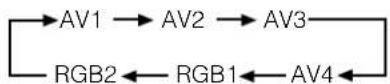
- Input can be switched by pressing the AV1, AV2, AV3, AV4, RGB1 or RGB2 buttons of the remote control.
- Input can be switched in the sequence of AV1 AV2 AV3 AV4 RGB1 RGB2 by pressing the INPUT SELECT button of the monitor.
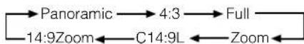
Size Switching
Each time the SIZE button of the remote control or the monitor is pressed, the screen display size will change in sequence and the status will be displayed at the bottom of the screen.
- DuringVIDEO signal input (AV1, AV2, AV3)
The size will be fixed Full mode and not change when receiving the component signal of 1080i/50, 1080i/60 or 720p/60.
Full
- During AV4 signal input
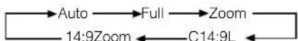
- [Auto] is the mode using the Switch signal from the equipment connected to AV4 terminal included in SCART connector No.8 pin which indicate the picture format of the video source. When Switch signal has not been detected, Default Zoom setting in the Function Menu is used to choose.
- And during some input mode except AV4, if the Switch signal is detected under the condition that [Auto] is selected for the picture size of AV4, the input mode will automatically transfer to AV4.
Display size selection diagram
| When you want to | Set the display size to | Input signal Displysplay screen Remarks | ||
| Play a 4:3 image in a 16:9 screen. | 4 : 3 | (4:3 signal) | ( ) | Blanking occurs on both sides. |
| Play a 4:3 image in a 16:9 screen with the height and width of the middle of the screen enlarged on equal scales and with both sides appearing somewhat enlarged. | Panoramic | ( ) | ||
| Play a 16:9 VISTA size image from a 4:3 image faithfully reproduced on the 16:9 screen. | Zoom | (Vista) | ( ) | • The 4:3 image is called a letterbox image. • In some cases, some slight blanking may remain at the top and bottom. |
| Play a 4:3 image faithfully from a 16:9 screen in the standard vertical size and horizontally squeezed.* | Full | (Squeeze) | ( ) | * An image with an aspect ratio of 16:9 shrunk horizontally to 4:3 to display in a 4:3 screen |
| Play a 14:9 image in a 16:9 screen expanded vertically and squeezed horizontally. | C14 : 9L | (14:9 signal) | ( ) | This mode is provided for the broadcasting program with WSS code-C14:9L. |
| Play a 14:9 image expanded vertically on the 16:9 screen. | 14 : 9Zoom | (14:9 signal) | ( ) | This mode is provided for the broadcasting program with WSS code-14:9Zoom. |
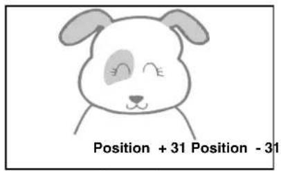
Vertical picture position can be adjusted for [Panoramic], [Zoom], [C14:9L] and [14:9Zoom] mode as follows.
- Press the SIZE button and SELECT buttons during picture size display.
- The position display will appear.
- The adjustment range of each picture size is as shown below.
[Panoramic] - 12 to + 12
[Zoom] - 31 to +31
[C14:9L] and [14:9Zoom] - 16 to +16
- When 1080i/50 or 1080i/60 component signal is received, vertical position can be adjusted only one step up. (The range: 0 to +1)
Press

Press
ATTENTION
Using a wide-screen monitor
This monitor has a screen mode selection feature. If an incompatible screen mode is selected to play certain software, such as a TV program, the image will appear different from the original. Take this into consideration when making screen mode choices.
- Use of this monitor in its enlarged display mode with the wide feature enabled in coffee shops, hotels and other establishments for commercial or public viewing purposes could infringe on the copyright holder's rights protected by Copyright Law.
- When a normal 4:3 image is displayed over the entire screen in the Panoramic mode, parts of the periphery of the image may disappear and/or appear distorted in some cases. Use the 4:3 mode to view images which were created in 4:3 mode.
This mode allows 4:3 content to be viewed without picture distortion.
OPERATING INSTRUCTIONS (continued)
Displaying MULTI PICTURE
If the PinP button on the remote control is pressed MULTI PICTURE will display.
Activating the P-in-P mode from the RGB input screen
Pressing the PinP button once will display 2 pictures.
- This mode can be available from RGB1(DVI-PC) and RGB2(RGB) input.
The speaker icon can be shifted left and right by pressing the and SELECT buttons; the audio of the video will be output from
the side on which the speaker icon is located.
- The sub-screen position can be selected up and down by pressing SELECT buttons.
- When the speaker icon appears on the left of the subscreen, as in the illustration at right, you can use the AV1, AV2, AV3 or AV4 buttons to select the subscreen input mode.
- Pressing the PinP button or the RETURN button will cancel the 2 pictures display.
- "Frequency Mode" in the Setup Menu should be set to Movie when sub-screen is the component signal of 1080i/50 or 1080i/60.
AV1: Displays the Video input signal of the sub-screen.
Activating the Split mode from the video input screen
Pressing the PinP button one time will display 2 pictures.
- The speaker icon can be shifted left and right by pressing the and SELECT buttons; the audio of the video will be output from the side on which the speaker icon is located.
The same video input mode cannot be selected for both screens at the s - Pressing the PinP button again or the RETURN button will cancel the 2 pictures display.
- When the Video input is set to RGB Video, this Split mode is not possible.
Refer to the table for 2 pictures (Split) mode.
2 Pictures (Split)
- Even if the input of the horizontal / vertical synchronizing signal (or video signal) stops in the MULTI PICTURE display, the mode will not change to power save mode.
- Please be careful since image retention will occur if the plasma monitor is left in a MULTI PICTURE display state for a long period of time.
Input Signal Screen Display
The input signal status can be displayed on the screen by pressing the RECALL button of the remote control or the monitor.
The display will go out in approximately 6 seconds.
OPERATING INSTRUCTIONS (continued)
PICTURE MENU

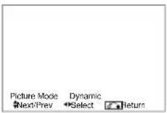


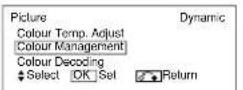
OPERATING INSTRUCTIONS (continued)
PICTURE MENU (continued)
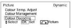
| Selected characters Setup hint | Dynamic | Natural | Dynamic: This setting is best for very bright ambient lighting. Natural: This setting is for normal lighting conditions. | |
| Picture Mode | →Dynamic →Natural → | Adjust for maximum visibility to suit the ambient brightness. This can be adjusted further till [+40] by pressing and holding cursor button at [+31]. The color for [+32] to [+40] numbers will change from white to magenta. This special mode is better for dark scenes. For normal viewing we recommend that the Contrast is set to [+31]. 'Panel Life' in the Function Menu should be set to Normal when this Contrast setting is adjusted. | ||
| Contrast | Narrows the gap between brightness and darkness. | Broadens the gap between brightness and darkness. | Adjust to taste. | |
| Brightness | Black is subdued for increased overall darkness. | Black is set off for increased overall brightness. | Adjust to taste. | |
| Colour | Darkens colours. Lightens colours. Adjust to taste. | |||
| Sharpness | Soft Sharp | Normally set to Centre position. Shift to the minus (-) side for a softer effect and plus (+) for a sharper picture. | ||
| Hue | Enhances red and weakens green. | Enhances green and weakens red. | This is adjustable when receiving PAL/SECAM signal. Then the character will be grayed out. Adjust for most realistic skin colour. | |
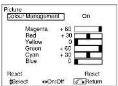
| Colour Temperature | Cool → Normal → Warm → Black / White → | Normally set to Cool. | ||
| Contrast Mode | Normal → Auto → Dynamic → | Dynamic: Emphasizes the differences between video shadings to improve the feeling of contrast. Normal : The gradation of an image is reproduced as faithfully as possible. Auto: Detects image brightness and automatically adjusts for natural brightness. | ||
| Reset | (Selects the Reset mode) | The original factory settings for the items of this Menu page can be restored by pressing the OK button. | ||
| YNR | Off → Low → High → | Performs picture signal noise reduction. Turn up to reduce noise. | ||
| CNR | Performs colour signal noise reduction. Turn up to reduce noise. It will be fixed as Off only when selecting DVI-STB mode. | |||
| Film Mode | →Off → On → | On: Automatically detects the movie film material and faithfully reproduces the original film image. Off: Set to OFF when switching between images does not appear natural. | ||
| PAL Comb Filter | →Off → On → | This is available only when receiving a PAL composite signal. Turn On to reduce the discolorations in fine picture detail and provide purer colour. | ||
| LTI | Off → Low → Middle → High → | Adjusts the sharpness of the picture signal. | ||
| CTI | Adjusts the sharpness of the colour signal. | |||
| Black Enhancement | Adjusts the black level compensation. | |||
| Auto Colour | →Off → On → | This is available only when receiving an NTSC composite/S Video signal. This monitors and adjusts the colour to maintain constant colour levels. It also maintains natural flesh tones while preserving fidelity of background colours. | ||
| Colour Temp. Adjustment | →Off → On → | Turn On when you wish to change colour temperature depending on the user's preference. | ||
| Amplitude | Red | Brighter scenes are decreased in reddish colour. | Brighter scenes are increased in reddish colour. | Adjust colour temperature depending on the user's preference. These settings are independently stored in each of the 4 Colour Temperature modes. |
| Green | Brighter scenes are decreased in greenish colour. | Brighter scenes are increased in greenish colour. | ||
| Blue | Brighter scenes are decreased in bluish colour. | Brighter scenes are increased in bluish colour. | ||
| Cut Off | Red | Dark scenes are decreased in reddish colour. | Dark scenes are increased in reddish colour. | |
| Green | Dark scenes are decreased in greenish colour. | Dark scenes are increased in greenish colour. | ||
| Blue | Dark scenes are decreased in bluish colour. | Dark scenes are increased in bluish colour. | ||
PICTURE MENU (continued)
| Selected characters Setup hint | Turn On when the original balance of each colour is required to adjust to suit user preferences. | ||
| Colour Management | Off On | ||
| Magenta | Magenta is weakened. Magenta is strengthened. | ||
| Red | Red is weakened. Red is strengthened. | ||
| Yellow | Yellow is weakened. Yellow is strengthened. | ||
| Green | Green is weakened. Green is strengthened. | ||
| Cyan | Cyan is weakened. Cyan is strengthened. | ||
| Blue | Blue is weakened. Blue is strengthened. | ||
| Colour Decoding | RGB←R←G←B← | Select the single colour screen you need to adjust R/G/B level individually depending on the user's preference. Set it back to RGB mode that indicates each colour (R/G/B) mode after adjusting. Press the OK button every time the setting is changed. | |
| Red | Darkens red only. Lightens red only. | This adjusts R/G/B level or tint to make the colour appear natural. These settings are independently stored in each of the 4 Colour Temperature modes. | |
| Green | Darkens green only. Lightens green only. | ||
| Colour | Darkens colours. Lightens colours. | ||
| Hue | Enhances red and weakens green. Enhances green and weakens red. | ||
FUNCTION MENU
2 item is added to the Menu shown in the page 19
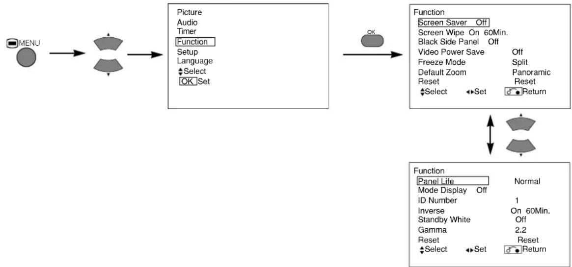
| Selected characters Setup hint | ← | → | |
| Video Power Save | →Off←On← | This is used to reduce power consumption for video input when there is no video signal. Setting it to On will place the monitor to the standby mode when the AV input with no signal is selected. | |
| Default Zoom | →Panoramic←4:3→14:9 Zoom← | This selects the screen display size that appears first when the power turned on. | |
OPERATING INSTRUCTIONS (continued)
SETUP MENU
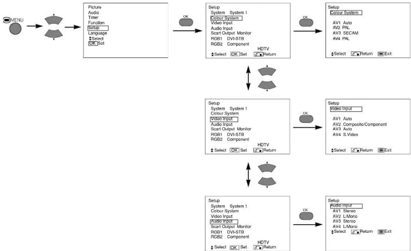
| Selected characters Setup hint | ||
| System | →System1←→System2← | |
| Colour System | ||
| AV1 | →Auto←→PAL←→SECAM←→NTSC3.58←→NTSC4.43← | This should correspond to the colour system of the signal from the equipment that is connected to the AV1 video input terminal. · Normally, set this to Auto. The system of the input signal will be automatically recognized. · If the input signal contains a lot of noise or has a low level at Auto and the operation is erratic, set this to match the input signal. · When the component signal is received, this setting is not available (grayed out). |
| AV2 | (Same to AV1) | |
| AV3 | ||
| AV4 | ||
| Video Input | ||
| AV1 | →Auto←→HDTV←→SDTV/DVD← | This should correspond to the signal mode of the signal from the equipment that is connected to AV1 video input terminal. · Normally, set this to Auto. The signal mode of the input signal will be automatically recognized. · If the input signal contains a lot of noise or has a low level at Auto and the operation is erratic, set this to match the input signal. |
| AV2 (1st step) | →RGB←→Composite/Component← | This should correspond to the signal mode of the signal from the equipment that is connected to AV2 video input terminal. |
| AV2 (2nd step) | →Auto←→HDTV←→SDTV/DVD← | This step should be set only when [Composite/Component] is selected on the 1st step. The procedure is same as for AV1. |
| AV4 | →S.Video←→Composite← | · If the signal from the equipment that is connected to the AV4 Scart input terminal is S.Video or Composite, set this to correspond to that signal. · If the signal is RGB, it will be automatically recognized and this setting will have no effect. |
OPERATING INSTRUCTIONS (continued)
SETUP MENU (continued)
| Selected characters Setup hint | |||
| Audio Input | |||
| AV1 | →Stereo←L/Mono← | This should correspond to the audio signal from the equipment that is connected to the AV1 audio input terminal. If the signal is monaural audio, set this to L/Mono. | |
| AV2 | (Same to AV1) | ||
| AV3 | |||
| AV4 | |||
| Scart Output | Not Available (grayed out) | ||
| RGB1 | →DVI-PC←DVI-STB← | This should correspond to the signal mode of the signal from the equipment that is connected to the RGB1 DVI terminal. | |
| RGB2 (1st step) | →RGB←Component← | This should correspond to the signal mode of the signal from the equipment that is connected to the RGB2 D-sub terminal. | |
| RGB2 (2nd step) | →Auto←HDTV←SDTV/DVD← | This step should be set only when [Component] is selected on the 1st step. This should correspond to the signal mode of the signal from the equipment that is connected to the RGB2 D-sub terminal. · Normally, set this to Auto. The signal mode of the input signal will be automatically recognized. · If the input signal contains a lot of noise or has a low level at Auto and the operation is found erratic, set this to match the input signal. | |
OTHER FEATURES
Automatic Store
Approximately 1 sec. after adjustment is completed, the adjustments will be recorded as shown in the table below.
| Menu Display Registration condition | |
| Picture | Picture Mode 1 setting is registered. |
| Contrast For every input function and every Picture Mode, 1 setting is registered. | |
| Brightness | |
| Colour | |
| Sharpness | |
| Hue | |
| Colour Temperature | |
| Contrast Mode | |
| YNR | |
| CNR | |
| Film Mode | |
| PAL Comb Filter | |
| LTI | |
| CTI | |
| Black Enhancement | |
| Auto Colour | |
| Colour Temp. Adjust | |
| R Amplitude For every Colour Temperature, 1 setting is registered. | |
| G Amplitude | |
| B Amplitude | |
| R Cut Off | |
| G Cut Off | |
| B Cut Off | |
| Colour Management For every input function and every Picture Mode, 1 setting is registered. | |
| Magenta 1 setting is registered. | |
| Red | |
| Menu Di | splay Registration | condition |
| Picture | Yellow | 1 setting is registered. |
| Green | ||
| Cyan | ||
| Blue | ||
| Colour Decoding | - | |
| Red | For every Colour Temperature, 1 setting is registered. | |
| Green | ||
| Colour | For every input function and every Picture Mode, 1 setting is registered. | |
| Hue | ||
| Function | Video Power Save | 1 setting is registered. |
| Default Zoom | ||
| Setup | System 1 setting is registered. | |
| Colour System | 1 setting is registered. | |
| AV1 | ||
| AV2 | ||
| AV3 | ||
| AV4 | ||
| Video Input - | ||
| AV1 | 1 setting is registered. | |
| AV2 | ||
| AV4 | ||
| Audio Input - | ||
| AV1 | 1 setting is registered. | |
| AV2 | ||
| AV3 | ||
| AV4 | ||
| RGB1 | ||
| RGB2 | ||
The previously recorded items will be lost.
Symptoms That Seemingly Appear to be Failures
Make the checks suggested below depending on the symptoms observed. If the symptoms remain uncorrected, contact your dealer.
CAUTION
Customer servicing can be hazardous.
| Symptom Point to check See page | ||
| ·The screen becomes dark and the images cannot be seen during VCR special playback (fast forward, rewind). | ·This sometimes occurs when a component output VCR such as the 480i is connected. This is not a malfunction; therefore, please take note that this may occur. When it does occur, change to composite output, or S video output. | - |
PRODUCT SPECIFICATIONS
This table shows the specifications when the optional video unit has been inserted.
| Panel | Display dimensions | Approx. 42 inches (922 (H) x 522 (V) mm, diagonal 1059mm) |
| Resolution | 1024 (H) x 1024 (V) pixels | |
| Net dimensions(excluding pedestal) | 1030 (W) x 636 (H) x 91 (D) mm | |
| Net weight(excluding pedestal) | 34.9kg | |
| Ambient conditions | Temperature | Operating: 5°C to 35°C, Storage: 0°C to 40°C |
| Relative humidity | Operating: 20% to 80%, Storage: 20% to 90% (non-condensing) | |
| Power supply | AC100 - 240V, 50/60Hz | |
| Power consumption/at standby | 365W / <3W | |
| Audio output | 12W + 12W (6Ω) | |
| (RGB input) | ||
| Input signals | Input terminals | RGB1 DVI input terminal (DVI-D) RGB1 audio input terminal (3.5mm Stereo Mini Jack) RGB2 analog RGB input terminal (D-sub 15-pin) RGB2 audio input terminal (3.5mm Stereo Mini Jack) |
| Video signals | 0.7 V/1.0 Vp-p, analog RGB (Recommended Signal) 480i, 576i, 480p, 576p, 1080i/50, 1080i/60, 720p/60 | |
| Sync signals | H/V separate, TTL level [2KΩ] H/V composite, TTL level [2KΩ] Sync on green, 0.3 Vp-p [75Ω] | |
| Recommended signal | 46 modes 29 42 | |
| (Video input) | ||
| Input signals | Input terminals | AV1: composite video input terminal (RCA) AV1: Y PB PR video input terminal (RCA) AV1: L/R audio input terminal (RCA) AV2: composite video input terminal (RCA) AV2: Y/G PB/B PR/R video input terminal (RCA) AV2: L/R audio input terminal (RCA) AV3: composite video input terminal (RCA) AV3: S video input terminal (RCA) AV3: L/R audio input terminal (RCA) AV4: composite video / S video / RGB / L/R audio input terminal (Scart) |
| Video signals | AV1: PAL, SECAM, NTSC4.43, NTSC3.58 AV1: 480i, 576i, 480p, 576p, 1080i/50, 1080i/60, 720p/60 AV2: PAL, SECAM, NTSC4.43, NTSC3.58 AV2: 480i, 576i, 480p, 576p, 1080i/50, 1080i/60, 720p/60, RGB AV3: PAL, SECAM, NTSC4.43, NTSC3.58 AV4: PAL, SECAM, NTSC4.43, NTSC3.58 AV4: RGB | |
| Video output Signal | OUTPUT (MONITOR): composite video monitor-output terminal (RCA) OUTPUT (MONITOR): L/R audio monitor- output terminal (RCA) AV4: composite video / L/R audio monitor-output terminal (SCART) | |
| Recommended signal | 15 modes 42 | |
The monitor takes at least 30 minutes to attain optimal picture quality.
Signal Input
RGB terminal (D-sub 15-pin connector)
| Pin | Input signal |
| 1 | R (Pr/Ch) |
| 2 | G or sync on green (Y) |
| 3 | B (Pb/Ce) |
| 4 | No connection |
| 5 | No connection |
| 6 | R.GND (Pr/Ch, GND) |
| 7 | G.GND (Y, GND) |
| 8 | B.GND (Pb/Cb, GND) |
| 9 | No connection |
| 10 | GND |
| 11 | No connection |
| 12 | [SDA] |
| 13 H. sync or H/V composite sync | |
| 14 | V(sync. [V.CLK] |
| 15 | [SCL] |
- When different kinds of input signals are simultaneously input to the monitor via a graphics board or the like, the monitor will automatically select the signals in the following priority order:
| Sync signal type | Priority |
| H/V separate sync. | 1 |
| H/V composite sync. | 2 |
| sync on Green * | 3 |
*There may be instances when correct display is not possible, even when displaying the signals listed on the following page. In this case, use H/V separate sync, H/V composite sync.
S-input connector pin specifications
| Pin Input signal | |
| 1 | Y |
| 2 Y-GND | |
| 3 | C |
| 4 C-GND | |
| Frame GND | |
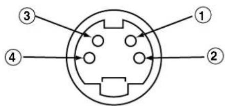
Scart connector pin specifications
| Pin | Signal Pin Signal | ||
| 1 | AUDIO OUT (RIGHT) | 12 | Not Used |
| 2 | AUDIO IN (RIGHT) | 13 | RGB-R GND |
| 3 | AUDIO OUT (LEFT/MONO) | 14 | GND |
| 4 | AUDIO GND | 15 | RGB-R / S.VHS CHROMINANCE IN |
| 5 | RGB-B GND | 16 | BLANKING SIGNAL |
| 6 | AUDIO IN (LEFT/MONO) | 17 | COMPOSITE VIDEO GND |
| 7 | RGB-B IN | 18 | BLANKING SIGNAL GND |
| 8 | AUDIO/RGB SWITCH / 16:9 | 19 | COMPOSITE VIDEO OUT |
| 9 | RGB-G GND | 20 | COMPOSITE VIDEO / S.VHS LUMINANCE IN |
| 10 | Not Used | 21 | GND / SHIELD (CHASSIS) |
| 11 | RGB-G IN |
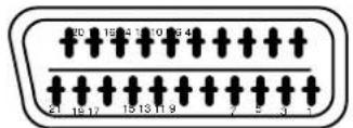
PRODUCT SPECIFICATIONS (continued)
Recommended Signal List
With Digital RGB signal input (RGB1 input)
| No. | Signal mode | Horizontal frequency (kHz) | Dot clock frequency (MHz) | Setup Menu Condition | Remarks | |||
| Signal Name | Resolution | Vertical frequency (Hz) | DVI-PC | DVI-STB | ||||
| 1 | VGA | 640 X 400 70.08 | 31.47 25.18 | ○ | ||||
| 2 | 640 X 480 59.94 | 31.47 25.18 | ○ | |||||
| 3 | W-VGA | 864 X 480 | 59.94 | 31.47 | 34.24 | ○ | WVGA type : On | |
| 4 | VESA | 640 X 480 72.81 | 37.86 31.50 | ○ | ||||
| 5 | 640 X 480 75.00 | 37.50 31.50 | ○ | |||||
| 6 | 640 X 480 85.01 | 43.27 36.00 | ○ | |||||
| 7 | 800 X 600 56.25 | 35.16 36.00 | ○ | |||||
| 8 | 800 X 600 60.32 | 37.88 40.00 | ○ | |||||
| 9 | 800 X 600 72.19 | 48.08 50.00 | ○ | |||||
| 10 | 800 X 600 75.00 | 46.88 49.50 | ○ | |||||
| 11 | 800 X 600 85.06 | 53.67 56.25 | ○ | |||||
| 12 | 1024 X 768 | 60.00 48.36 65.00 | ○ | |||||
| 13 | 1024 X 768 | 70.07 56.48 75.00 | ○ | |||||
| 14 | 1024 X 768 | 75.03 60.02 78.75 | ○ | |||||
| 15 | 480p | 720 X 480 | 59.94 | 31.47 | 27.00 | ○ | EIA-861 | |
| 16 | 720p/60 | 1280 X 720 | 60.00 | 45.00 | 74.25 | ○ | EIA-861 | |
| 17 | 1080i/60 | 1920 X 1080 | 60.00 | 33.75 | 74.25 | ○ | EIA-861 | |
| No. | Signal mode | Horizontal frequency (kHz) | Dot clock frequency (MHz) | Remarks | ||
| Signal Name | Resolution | Vertical frequency (Hz) | ||||
| 1 | NTSC4.43 | 525 59.94 15 | 73 — | |||
| NTSC3.58 | ||||||
| 2 | PAL | 625 50.00 15 | 63 — | |||
| SECAM | ||||||
With R, G, B Video input (AV2 and AV4 input).
| No. | Signal mode | Horizontal frequency (kHz) | Dot clock frequency (MHz) | Remarks | ||
| Signal Name | Resolution | Vertical frequency (Hz) | ||||
| 1 | NTSC4.43/3.58 | 525 | 59.94 | 15.73 | - | |
| PAL, SECAM | 625 | 50.00 | 15.63 | |||
With component input (AV1, AV2 and RGB2-component input).
| No. | Signal mode | Horizontal frequency (kHz) | Dot clock frequency (MHz) | Remarks | ||
| Signal Name | Resolution | Vertical frequency (Hz) | ||||
| 1 576i 576 50.00 15.63 | — | |||||
| 2 480i 480 59.94 15.73 | — | |||||
| 3 576p 576 50.00 31.26 | — | |||||
| 4 480p 480 59.94 31.47 | — | |||||
| 5 1080i/50 1080 50.00 | 28.13 — | |||||
| 6 1080i/60 1080 60.00 | 33.75 — | |||||
| 7 720p/60 720 60.00 45.00 — | ||||||
The monitor differentiates the signal modes according to the horizontal and vertical frequencies and the horizontal and vertical sync signal polarities. Note that different signals having all these elements alike may be handled as the same signal.
- Displaying images with more than 512 lines of vertical resolution at Full display (compressed display) can result in the interpolation of stripes.
Optional Tuner Unit Function
The optional tuner unit works when installed with the optional video unit.
Additional functions when the optional tune unit is installed are as follows: (4356
COMPONENT NAMES
Remote control (provided for the optional tuner unit)
This type of remote control is provided for the optional tuner unit as a substitute for the one shown in page 9.
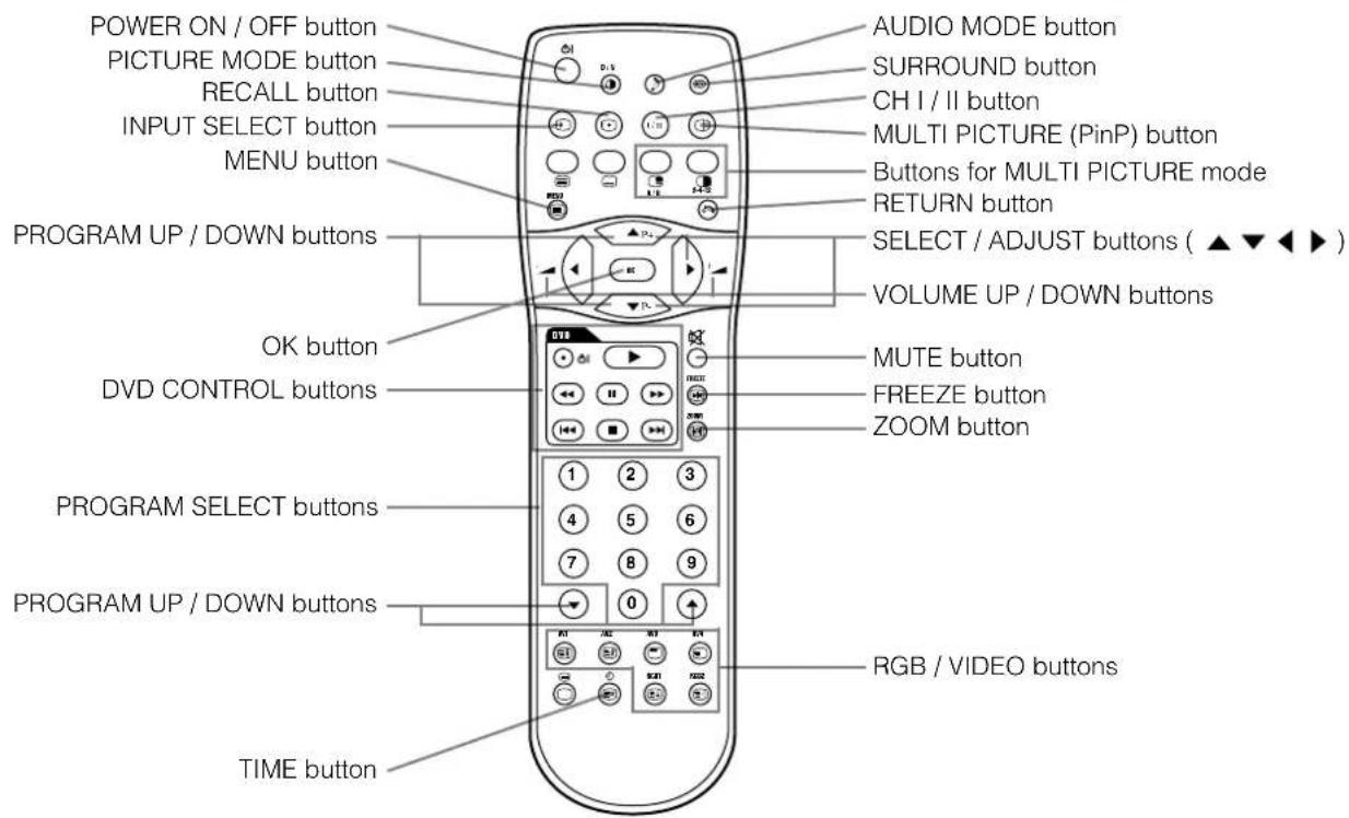
Loading Batteries
1. Open the battery cover.
- Slide back and remove the battery cover in the direction of the arrow.
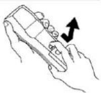
2. Load the batteries.
- Load the two Size AA batteries included, matching polarity marking on the batteries to those on the case.
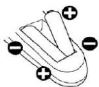
3. Close the battery cover.
- Replace the battery cover in the direction of the arrow and snap it back into place.
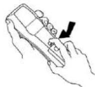
CAUTION
- Do not use new and old batteries together. The batteries could explode or leak, resulting in fires, physical injury, or stains.
- When loading batteries, observe their correct polarities as marked on the product. If loaded in the wrong direction, the batteries could explode or leak, resulting in fires, physical injury, or stains.
Handling the Remote Control
Use the remote control within about 5m from front of the unit's remote-control sensor and within 30 degrees on both sides.
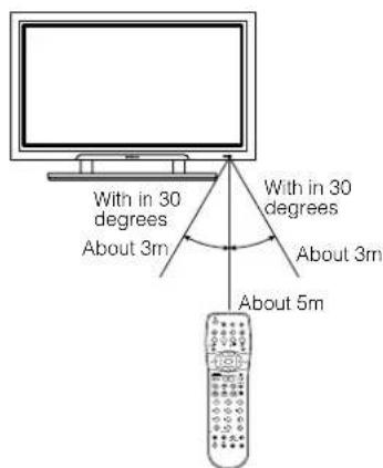
ATTENTION
- Do not drop or impact the remote control.
- Do not splash the remote control with water or put it on a wet object to avoid possible failures.
Before leaving the remote control out of use for an extended period of time, remove the batteries from it. - If the remote control begins to lack responsiveness, replace the batteries.
- Strong light such as direct sunlight impinging on the photoreceptor of the remote control can cause operational failure. Position this unit to avoid direct contact with such light.
Remote control (provided for the optional tuner unit) (continued)
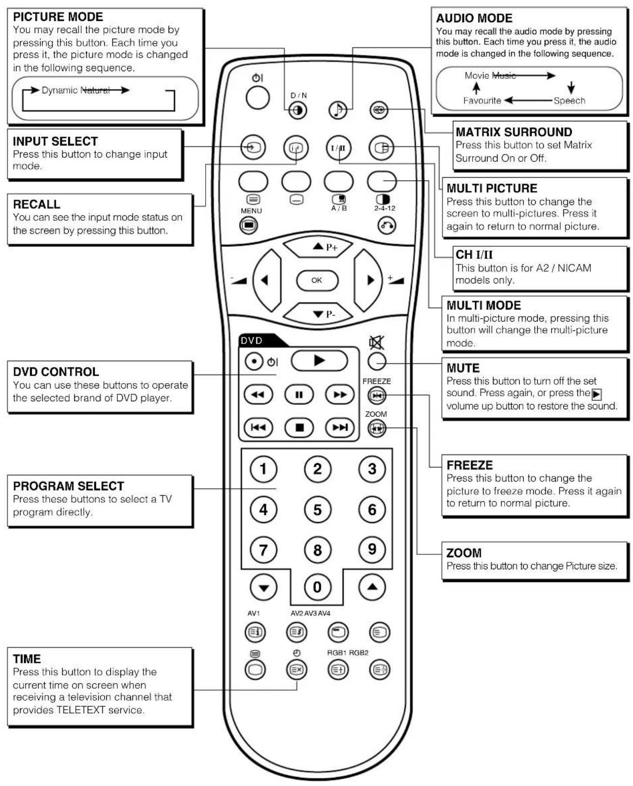
Remote control (provided for the optional tuner unit) (continued)
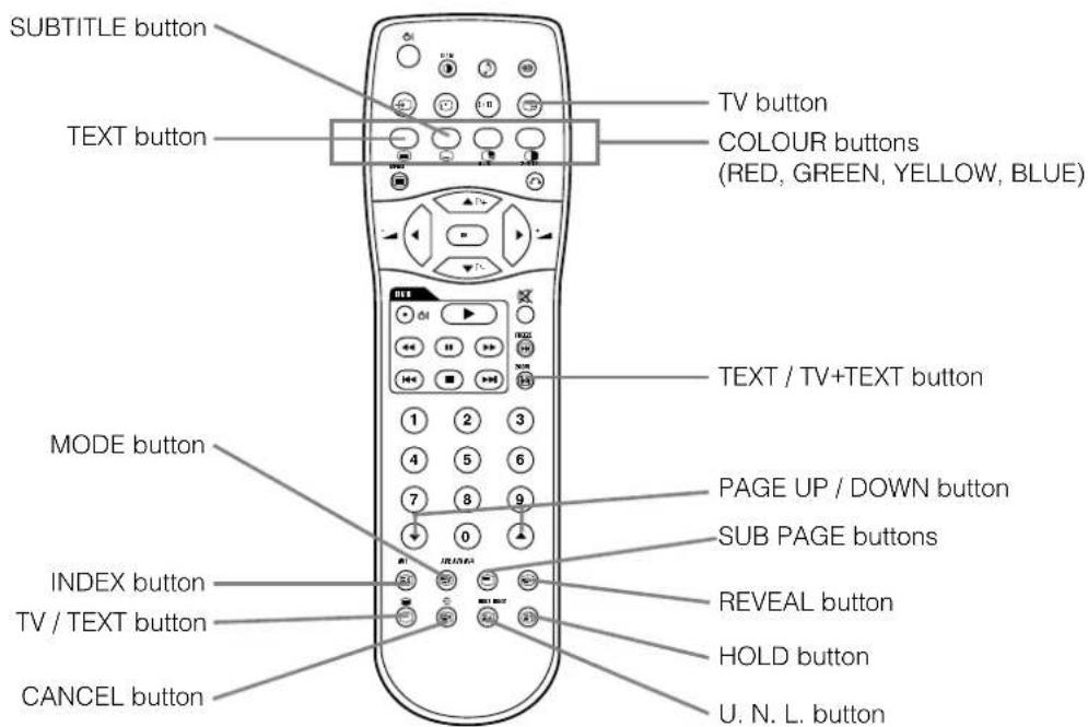
[Buttons for TELETEXT Mode]
TELETEXT FUNCTION
| Buttons on Remote Control Function | |
| TEXT | Press this to use the TELETEXT services. |
| TV | Press this to return to the TV mode when in the TELETEXT mode. |
| TV / TEXT | This switches the receiver between the TV mode and the TELETEXT mode. |
| TEXT / TV + TEXT | In TELETEXT mode, this button switches between TV+TEXT screen (split) and TELETEXT only. |
| MODE | This selects the FASTEXT and FAVOURITE modes. |
| INDEX | This selects the P100 page. |
| SUB PAGE | This allows receiving of a sub page. When the button is pressed, "S*****" will be displayed at the top left of the screen. |
| SUB TITLE | Use this to access a subtitle service directly rather than through a TELETEXT service (subject to subtitle service broadcasting). |
| CANCEL | This allows the screen to return to the TV mode temporarily while searching for a required text page. When the required text page has been received, the page number will be displayed at the top left of the screen. Press the CANCEL button again to display the TELETEXT screen. |
| RED GREEN YELLOW BLUE | Each of these buttons selects a link page displayed at the lower part of the screen. A FAVOURITE page can also be stored in the memory using one of the colours. It can then retrieve the page stored by pressing the appropriate colour button. To store a FAVOURITE page : • press the MODE button ; • press a colour button for the FAVOURITE page ; • enter the FAVOURITE page number to be stored and press the same colour button again to confirm. |
| U. N. L | Each time this button is pressed, the screen display mode changes through the following. normal state → upper half screen enlarged lower half screen enlarged |
| HOLD | This holds the page currently being displayed on the screen. Instead of the page number, a " " indicator appears at the top of the screen. Press this button again to release the hold state. |
| REVEAL | This allows hidden information (found on some teletext pages) to be displayed on the screen. |
| PAGE UP / DOWN | These buttons increase / decrease the TELETEXT page number. |
NOTE
- Certain pages do not show linked pages at the bottom of the screen. To display linked pages, press the INDEX button.
INSTALLATION INSTRUCTIONS
Connecting Antenna
Make sure that the power switch of the monitor is turned off.
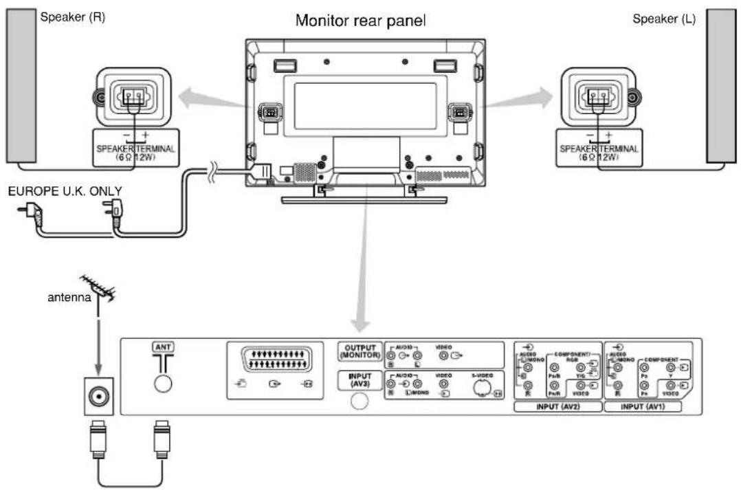
Precautions when connecting the antenna
- Please use a coaxial cable which is not prone to interference to connect the antenna. Avoid using a parallel flat feeder wire as interference may occur, causing reception to be unstable and stripe noise to appear on the screen.
- Avoid using an indoor antenna as this may cause interference. Please use CATV net or outdoor antenna.
- Keep the power cord as far away from the antenna wire as possible.
If there is noise apparent in the picture of VHF-Low band channel, please use double-shielded cable (not provided) for RF LEADS to reduce the noise.
OPERATING INSTRUCTIONS
The functions of the buttons located on the bottom of the monitor change as shown below:
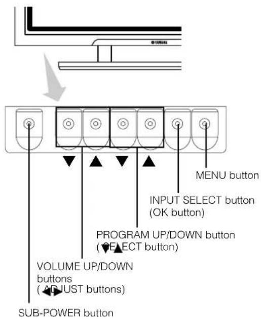
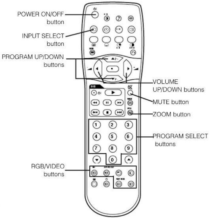
- ( ) indicates the function while the MENU is displayed on the screen.
Input Switching Size Switching
-
Input can be switched by pressing the AV1, AV2, AV3, AV4, RGB1 or RGB2 buttons of the remote control. And the way to return to a TV channel is as follows:
-
Pressing INPUT SELECT button at RGB2 input screen.
-
Pressing some PROGRAM SELECT buttons and select a TV channel.
-
Pressing PROGRAM UP/DOWN buttons at the screen without OSD(On-screen display).
-
Input can be switched in the sequence of TV AV1 AV2 AV3 AV4 RGB1 RGB2 by pressing the INPUT SELECT button of the monitor or the remote control.
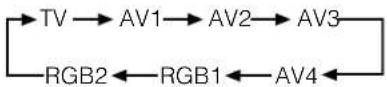
Each time the ZOOM button of the remote control is pressed, the screen display size will change and the status will be displayed at the bottom of the screen.
During TV mode
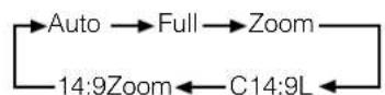
- [Auto] is a mode which uses WSS (Wide Screen Signals), which identify the picture format movies and programs are broadcast in.
Various broadcast stations now transmit WSS. It can be detected and the monitor will automatically switch to the correct format.
However, some broadcasters do not transmit WSS, and in these cases monitor will not recognize which format is being transmitted. Therefore, the Default Zoom setting in the Function Menu is used to choose when a WSS has not been sent or has not been detected.
OPERATING INSTRUCTIONS (continued)
Displaying MULTI PICTURE
If the MULTI PICTURE button on the remote control is pressed, multiple pictures will display. Three types of display can be selected by pressing the MULTI MODE button on the remote control.
The multi picture mode will change in the following sequence each time the MULTI MODE button is pressed.
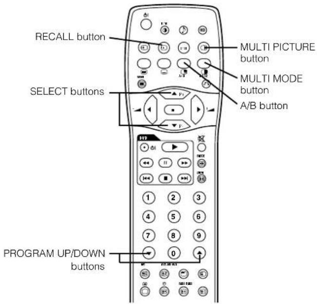
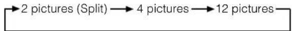
Activating the Split mode from the TV screen
Pressing the MULTI PICTURE button one time will display 2 pictures.
- The speaker icon can be shifted left and right by pressing the A/B button; the audio will be output from the side on which the speaker icon is located.
The same signal input cannot be selected for both screens at the same time.
The TV channel can be changed by pressing the and PROGRAM UP/DOWN buttons on the remote control. - The signal input mode of picture-A or picture-B (the one that the speaker icon is located on) can be selected by pressing INPUT SELECT button on the remote control.
- Pressing the MULTI PICTURE button once again will cancel the multi picture mode.
- When the Video input is set to RGB Video, multi picture mode is not possible.
Refer to the table for 2 pictures (Split) mode. 49
Activating the 4 pictures mode from the TV screen
Pressing the MULTI MODE button one time at the 2 pictures mode will display 4 pictures.
- Press [A/B] button to select picture A or picture B indicated by a red triangle. For pictures on right, press SELECT buttons to select picture. The selected channel number would change green.
The TV channel can be changed by pressing the PRG RAM UP/DOWN buttons on the remote control.
The audio can only be output from picture A in the 4 picture mode.
The same signal input mode cannot be selected for each screens at the same time. - Pressing the MULTI PICTURE button from the 4 picture mode will cancel the multi picture mode. Pressing the MULTI PICTURE button again will display the 4 pictures.
Refer to the table for 4 pictures mode. 49
Activating the 12 pictures mode from the TV screen
Pressing the MULTI MODE button one time at the 4 pictures mode will display 12 pictures.
- Starting from channel 1, preset channels will automatically display in sequence on the 12 windows.
This function activates only in TV mode.
After several seconds, it refreshes the picture one by one. -
Pressing the MULTI PICTURE button at the 12 picture mode will cancel the multi picture mode. Pressing the MULTI PICTURE button again will display the 12 pictures again.
-
Pressing the MULTI MODE button from the 12 picture mode will display the 2 pictures (Split) mode.
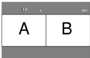
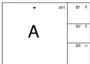
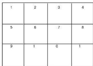
NOTE
- Even if the input of the horizontal / vertical synchronizing signal (or video signal) stops during multi picture display, the mode will not change to power save mode.
- Please be careful since image retention will occur if the plasma display is left in a multi picture display state for a long period of time.
OPERATING INSTRUCTIONS (continued)
Displaying MULTI PICTURE (continued)
2 Pictures (Split)
| Input terminal AV1~AV4 AV1, AV2 RGB1 RGB2 | TELE TEXT | ||||||||||
| Main\Sub | PAL SECAM | NTSC3.58 NTSC4.43 | 576i 576p | 480i 480p | 1080i/50 | 1080i/60 | 720p/60 S | 1B Component | |||
| AV1 ~AV4 | PAL, SECAM | ○ | ○ | ○ | ○ | ○ | ○ | ○ | |||
| NTSC3.58/4.43 | ○ | ○ | ○ | ○ | ○ | ○ | |||||
| AV1 AV2 | 576i, 576p | ○ | ○ | ||||||||
| 480i, 480p | ○ | ○ | |||||||||
| 1080i/50 | ○ | ○ | |||||||||
| 1080i/60 | ○ | ○ | |||||||||
| 720p/60 | ○ | ○ | |||||||||
| RGB1 STB | |||||||||||
| RGB2 Component | ○ | ○ | ○ | ○ | ○ | ○ | |||||
( Available)
| Main Sub |
4 Pictures
| Input terminal AV1-AV4 AV1, AV2 RGB1 RGB2 | TELE TEXT | ||||||||||
| Main\Sub | PAL SECAM | NTSC3.58 NTSC4.43 | 576i 576p | 480i 480p | 1080i/50 | 1080i/60 7 | 20p/60 ST | TB Component | |||
| AV1~AV4 | PAL, SECAM | ○ | ○ | ||||||||
| NTSC3.58/4.43 | ○ | ○ | |||||||||
| AV1AV2 | 576i, 576p | ○ | ○ | ||||||||
| 480i, 480p | ○ | ○ | |||||||||
| 1080i/50 | ○ | ○ | |||||||||
| 1080i/60 | ○ | ○ | |||||||||
| 720p/60 | ○ | ○ | |||||||||
| RGB1 STB | |||||||||||
| RGB2 Component | ○ | ○ | |||||||||
( Available)
| Main | Sub 1 |
| Sub 2 | |
| Sub 3 |
Input Signal Screen Display
The TV channel status can be displayed on the screen by pressing the RECALL button of the remote control.
The display will disappear in approximately 6 seconds.
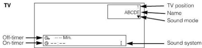
OPERATING INSTRUCTIONS (continued)
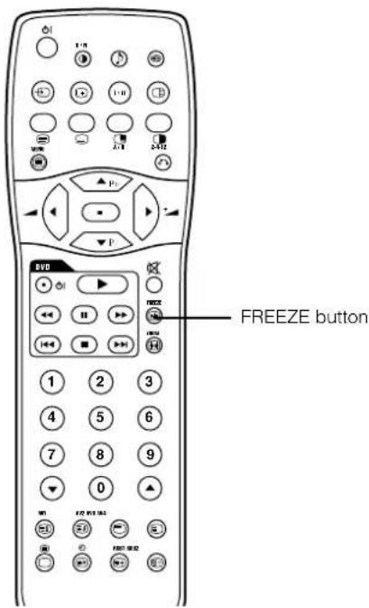
Picture Freezing
When the FREEZE button on the remote control is pressed, the screen transfers into the freeze mode.
- There are two types of Picture Freeze mode, Split and Strobe. You can select them at the "Freeze Mode" setting of the Function Menu.
The Split mode will display 2 pictures from the same source on the screen with one active picture and the other still.
The Strobe mode will display 12 pictures with the last picture active, while other 11 windows are still. - Pressing the FREEZE button again changes the screen back to the normal picture.
This function is also available from video input mode besides TV mode. Refer to the table for Freeze function as below:
Refer to the page 37. (In the same way as when the optional video unit is attached) But 1 item is added and 5 items are deleted.
| Selected characters Setup hint | ▲ | ▲ | ||
| Freeze Mode | →Split←→Strobe← | This switches the display condition of the FREEZE mode between Split (2 pictures) and Strobe (12 pictures). | ||
| Mode Display | Not Available (grayed out) | |||
| ID Number | Not Available (grayed out) | |||
| Inverse | Not Available (grayed out) | |||
| Standby White | Not Available (grayed out) | |||
| Gamma | Not Available (grayed out) | |||
OPERATING INSTRUCTIONS (continued)
SETUP MENU
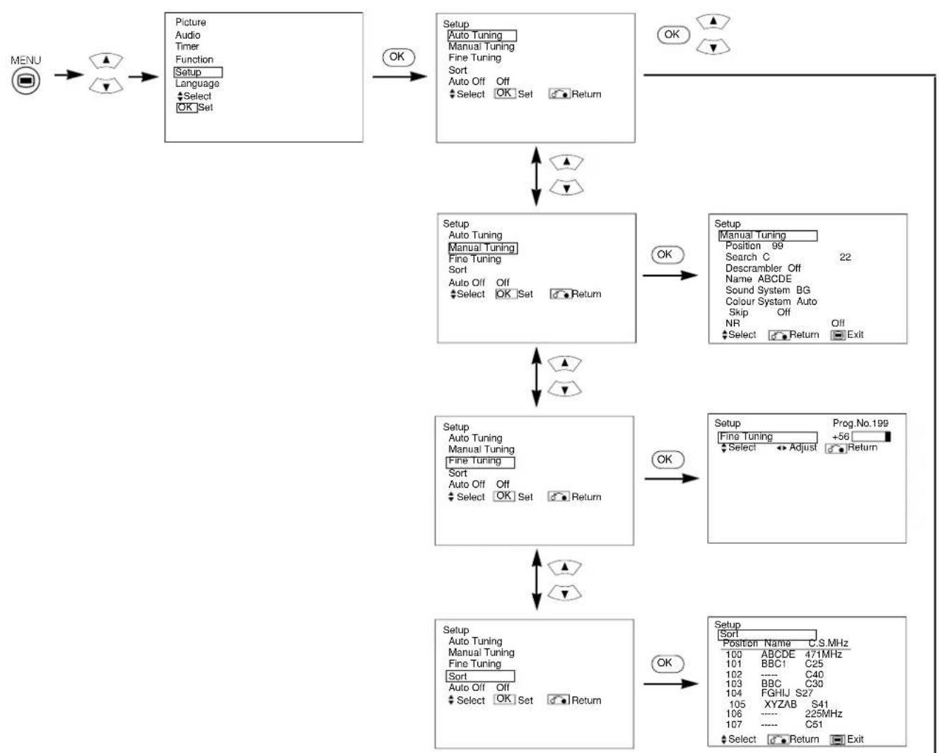
[During TV mode]
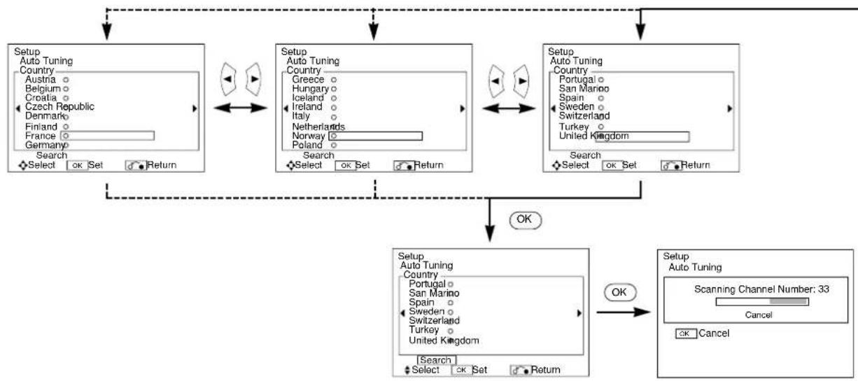
OPERATING INSTRUCTIONS (continued)
SETUP MENU (continued)
| Selected characters Setup hint | ▶ | ||
| Auto Tuning | |||
| Country | →(Page1) → (Page2) → (Page3) ← | Select the country name using the ▼▲SELECT buttons and press OK button. ·If some required stations could not be preset using the auto tuning function, select and preset the required station in the required position using the manual tuning operation. | |
| Search | - | - | Press the OK button and it starts the auto tuning. |
| Manual Tuning | |||
| Position | →1←→2←→3←→199←→AV00← | Set the position number. This also can be set by ▼▲PROGRAM UP/DOWN buttons. | |
| Search(C--)(S--)(--MHz) | - | - | Select the channel entry method. Enter a two digit channel number (CH), a two digit S-band number, or a 3 digit frequency (MHz). |
| - | - | Use the 0-9 NUMBER buttons to enter a two digit number. If the number is a standard channel number, the unit begins searching for the channel. | |
| - | - | Use the 0-9 NUMBER buttons to enter a two digit number. If the number is a standard S-band number, the unit begins searching for the channel. | |
| - | - | Use the 0-9 NUMBER buttons to enter a three digit number. If the number is a standard frequency, the unit begins searching for the channel. | |
| Descrambler | →Off → On ← | Set this to Off normally. If it is set to On, the AV4 (Scart) terminal operates as TV signal input, and the screen changes to display AV4 (Scart) input signal automatically. | |
| Name | □←→□←→□←→□(□a letter) | This is used to input a 5 digit name for a TV station. After fixing the cursor on the first digit, select a letter by ▼▲SELECT buttons and move to the next digit by ▶ADJUST button. Press the OK button again when finished. ·Selectable letters are "0"~"9", "A"~"Z", "+","-",""(blank),"(comma) and ";"(period). | |
| Sound System | BG←I←DK←L←L←L← | Select one of 5 different settings for the sound system. | |
| Colour System | Auto←PAL←SECAM←NTSC3.58←NTSC4.43← | Select one of 5 different settings for the colour system. | |
| Skip | Off←On ← | If this is set to On, the selected position will be skipped while selecting positions by PROGRAM UP/DOWN buttons. This is automatically set to On for non-broadcasting channels. | |
| NR | Off←On ← | If this is set to On, it helps to reduce the noise interference visible on the screen, especially in weaker signal reception areas. | |
| Fine Tuning | Decreasing the frequency data for the main tuner | Increasing the frequency data for the main tuner. | After completing fine-tuning, press the RETURN button to exit this mode. ·The variable range is -56 ~ +56. |
| Sort | |||
| (Position list designated rows) | - | - | Move the cursor to the row of the channel you wish to change, and press the OK button. The display characters change to green. Use the ▼▲SELECT buttons to move the row to the disired location, and press the OK button when you have finished. Press the RETURN button to exit. |
| Auto Off | →Off ← On ← | If this is set to On, the power will be turned off when there is no transmission signal and no operation for about 10 minutes in the TV mode. | |
[DuringVIDEO signal input]
1 item is added to the Menu shown in the page 39
| Selected characters Setup hint | ▲ | ▲ | |
| Scart Output | →TV← Monitor← | TV:AV4 (Scart) output will be fixed as TV signal output. Monitor:AV4 (Scart) output can view the same image as displayed on the main unit. It is possible to monitor only the composite video signal from AV1, AV2, or AV3 input that is displayed on the screen at the time. ·If Descrambler is set to On, it will be fixed as TV automatically. | |
OPERATING INSTRUCTIONS (continued)
OTHER FUNCTIONS
A2/NICAM/SoundMultiplex
- The CH I / II button is only useful for NICAM and sound multiplex signals. Otherwise pressing this button will have no effect.
BILINGUAL/DUAL sound broadcast
When bilingual program is received, sound mode display appears in yellow as shown on right. Press the CH I / II button to select the sound to be heard. Each time the button is pressed, I, II or (force mono) appear cyclically on the screen. When receiving NICAM signals, NICAM display will appear as below.
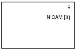
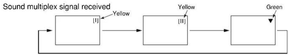
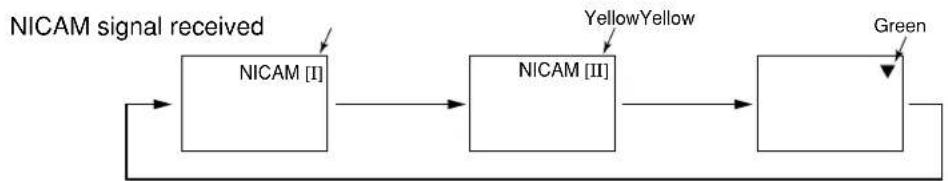
Select I, II or (force mono) to hear the CHI, CH II or MONO broadcast respectively.
STEREO sound broadcast
When a stereo program is received, the sound mode display will appear in red, and you can press the CH I / II button to select either stereo or mono sound.
Each time the button is pressed, or (force mono) appear cyclically on the screen. When receiving NICAM signals, the NICAM display will appear as below.
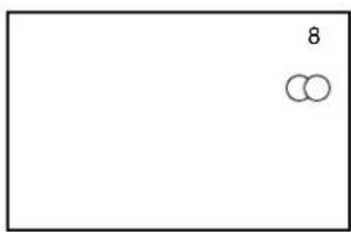
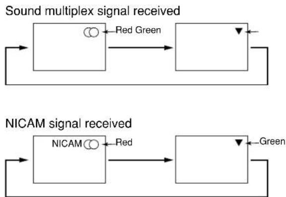
Select or (force mono) to hear the STEREO or MONO broadcast respectively.
Monaural sound broadcast
When a monaural program is received, the sound mode display will appear in green. You can press the CH I / II button to swith the sound mode between monaural and forced mono (sounds are identical). Each time the button is pressed, or (force mono) appear cyclically on the screen.
NOTE
If the sound signal is not strong enough for quality reception, press the CH I / II button until appears on the screen to receive a clear mono sound. If the sound signal has hiss noise or the plasma monitor keeps switching between stereo and mono mode due to signal condition, press the CH I / II button until appears on the screen to receive a clear mono sound.
OPERATING INSTRUCTIONS (continued)
OTHER FUNCTIONS (continued)
DVD Player Selection
- You can use this remote control to operate various, brands of DVD player by pressing the following buttons on the remote control simultaneously.
| YAMAHA | Press | RECALL | 3 or 5 | OR RECALL |
Other brands
| Brands of DVD Player Press | Brands of DVD Player Press | ||
| Hitachi RCA | RECALL 1 | RECALL 9 | |
| Pioneer Mitsubishi | RECALL 2 | RECALL 0 | |
| Panasonic Onkyo | RECALL 3 | RECALL INDEX | |
| Toshiba Zenith | RECALL 4 | RECALL MODE | |
| Philips Orion | RECALL 5 | RECALL SUB PAGE | |
| JVC Shinco | RECALL 6 | RECALL CANCEL | |
| Samsung Skyworth | RECALL 7 | RECALL REVEAL | |
| Sony Bubuko | RECALL 8 | RECALL TV/TEXT |
Example
To operate a YAMAHA DVD player, press and hold the RECALL button, followed by the 3 or 5 button.
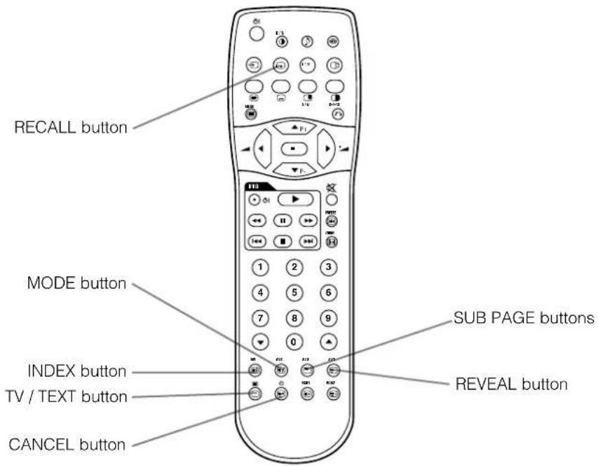
NOTE
- Not all models of the listed brands can be operated using this remote control.
Symptoms That Seemingly Appear to be Failures
Make the checks suggested below depending on the symptoms observed. If the symptoms persist, contact your dealer.
CAUTION
Customer servicing can be hazardous.
| Symptom Possible reason | Remedy | |
| snowy picture - poor sound | (1) Connection of antenna cable to the TV is poor.(2) Corroded or poor antenna connections.(3) Antenna has moved position.(4) Adverse weather conditions.(5) Transmitter problems. | (1) Make new connection and/or change antenna plug.(2) Make new connections or renew cable.(3) Re-align antenna.(4) None.(5) Check with local Operator. |
| multiple images - sound O.K | (1) Antenna has moved position.(2) TV not tuned correctly.(3) Adverse weather conditions.(4) Transmitter problems.(5) AV Input not set correctly. | (1) Re-align antenna.(2) Re-tune or fine tune TV.(3) None.(4) Check with local Operator.(5) Check the external equipment connected. |
| intermittent interference | (1) Interference from electrical or mechanical motors, fluorescent lights, portable radios etc. | (1) Check devices for shielding and renew if necessary or move further from TV. |
| no picture or sound | (1) TV may be in AV mode.(2) Picture/sound selling set to minimum.(3) TV in standby or power save mode. | (1) Press the INPUT SELECT button or ①to ⑨buttons on your remote control to return to normal TV mode.(2) Check picture / sound controls (go to MAIN MENU).(3) Press POWER ON / OFF button. |
PRODUCT SPECIFICATIONS
This table shows the specifications when the optional video unit and tuner unit have been inserted.
| Panel | Display dimensions | Approx. 42 inches (922 (H) x 522 (V) mm, diagonal 1059mm) |
| Resolution | 1024 (H) x 1024 (V) pixels | |
| Net dimensions(excluding pedestal) | 1030 (W) x 636 (H) x 91 (D) mm | |
| Net weight(excluding pedestal) | 34.9kg | |
| Ambient conditions | Temperature | Operating: 5°C to 35°C, Storage: 0°C to 40°C |
| Relative humidity | Operating: 20% to 80%, Storage: 20% to 90% (non-condensing) | |
| Power supply | AC100 - 240V, 50/60Hz | |
| Power consumption/at standby | 365W / <3W | |
| Audio output | 12W + 12W (6Ω) | |
| (RGB input) | ||
| Input signals | Input terminals | RGB1 DVI input terminal (DVI-D) RGB1 audio input terminal (3.5mm Stereo Mini Jack) RGB2 analog RGB input terminal (D-sub 15-pin) RGB2 audio input terminal (3.5mm Stereo Mini Jack) |
| Video signals | 0.7 V/1.0 Vp-p, analog RGB (Recommended Signal) 480i, 576i, 480p, 576p, 1080i/50, 1080i/60, 720p/60 | |
| Sync signals | H/V separate, TTL level [2KΩ] H/V composite, TTL level [2KΩ] Sync on green, 0.3 Vp-p [75Ω] | |
| Recommended signal | 46 modes 29 42 | |
| (Video input) | ||
| Input signals | Input terminals | AV1: composite video input terminal (RCA) AV1: Y PB PR video input terminal (RCA) AV1: L/R audio input terminal (RCA) AV2: composite video input terminal (RCA) AV2: Y/G PB/B PR/R video input terminal (RCA) AV2: L/R audio input terminal (RCA) AV3: composite video input terminal (RCA) AV3: S video input terminal (RCA) AV3: L/R audio input terminal (RCA) AV4: composite video / S video / RGB / L/R audio input terminal (Scart) |
| Video signals | AV1: PAL, SECAM, NTSC3.58, NTSC4.43 AV1: 480i, 576i, 480p, 576p, 1080i/50, 1080i/60, 720p/60 AV2: PAL, SECAM, NTSC3.58, NTSC4.43 AV2: 480i, 576i, 480p, 576p, 1080i/50, 1080i/60, 720p/60, RGB AV3: PAL, SECAM, NTSC3.58, NTSC4.43 AV4: PAL, SECAM, NTSC3.58, NTSC4.43 AV4: RGB | |
| Recommended signal | OUTPUT (MONITOR): composite video monitor-output terminal (RCA) OUTPUT (MONITOR): L/R audio monitor- output terminal (RCA) AV4: composite video / L/R audio output terminal (SCART) | |
| Recommended signal | 15 modes 42 | |
| (RF input) | ||
| Input signals | Input terminals | ANT: 75ΩUnbalanced |
| RF Video System | PAL B, G, H/I/D, K SECAM B, G/D, K/K1/L, L' | |
- The monitor takes at least 30 minutes to attain of optimal picture quality.
Manuel Utilisateur
TruBass TruBass by SRS(●)
CHARACTERISTIQUES DU PRODUIT 27
CHARACTERISTIQUES DU PRODUIT
(Panoramic) -12 a +12
(Zoom) -31 à +31
INSTRUCTIONS D'OPÉRATION (suite)
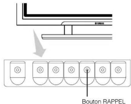

Affichage de MULTI PICTURE (MULTI IMAGE)
INSTRUCTIONS D'OPÉRATION (suite)
MENU IMAGE
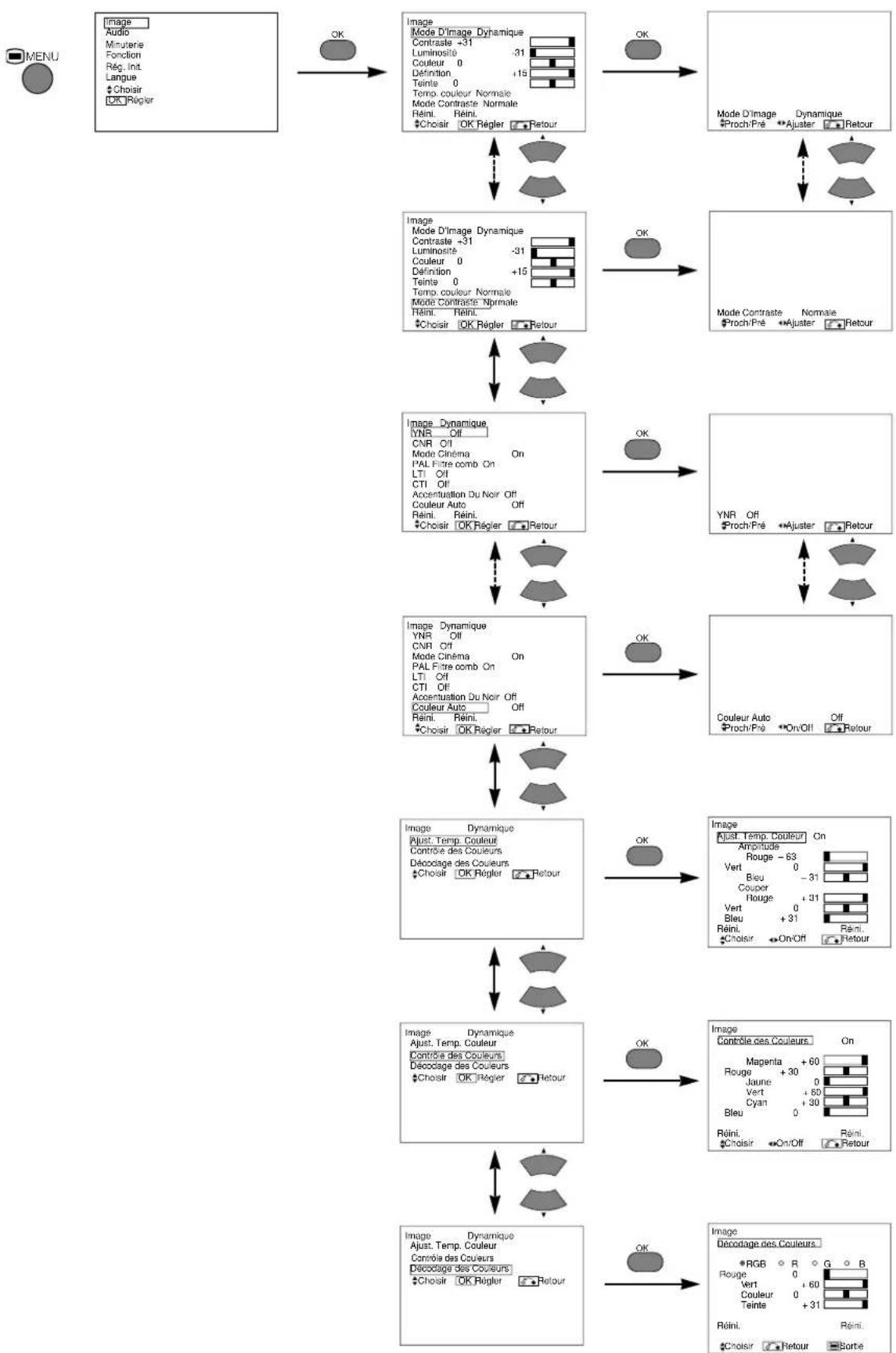
INSTRUCTIONS D'OPÉRATION (suite)
MENU IMAGE (suite)
INSTRUCTIONS D'OPÉRATION (suite)
MENU IMAGE (suite)
INSTRUCTIONS D'OPÉRATION (suite)
MENURÉGLAGE INITIAL
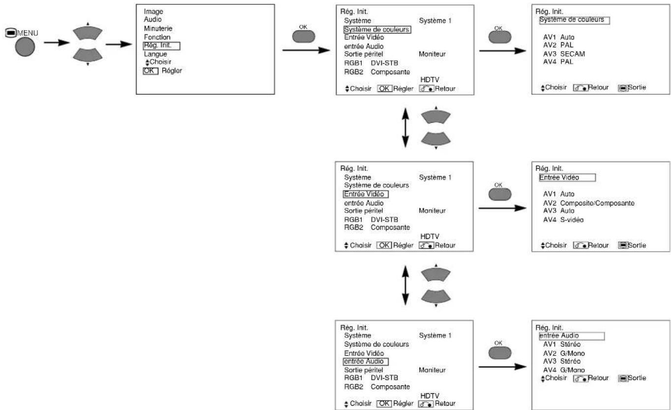
INSTRUCTIONS D'OPÉRATION (suite)
MENURÉGLAGE INITIAL (suite)
CHARACTERISTIQUES DU PRODUIT
CHARACTERISTIQUES DU PRODUIT (suite)
INSTRUCTIONS D'OPÉRATION (suite)
Affichage de MULTI IMAGE
INSTRUCTIONS D'OPÉRATION (suite)
Affichage de MULTI IMAGE (suite)
INSTRUCTIONS D'OPÉRATION (suite)
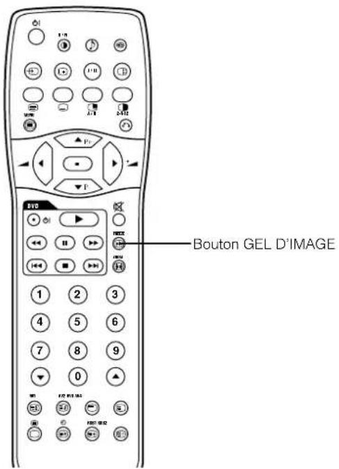
Gel D'images
INSTRUCTIONS D'OPÉRATION (suite)
MENURÉGLAGE INITIAL
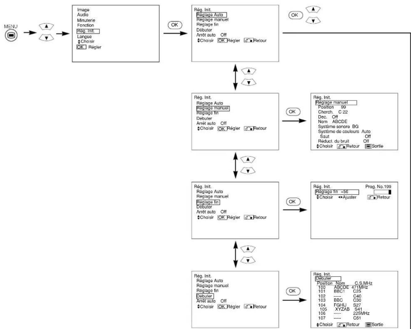
[Durant le mode TV]
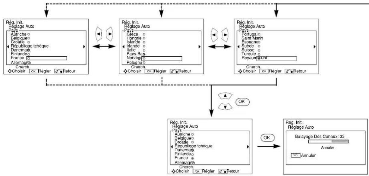
INSTRUCTIONS D'OPÉRATION (suite)
MENURÉGLAGE INITIAL (Suite)
INSTRUCTIONS D'OPÉRATION (suite)
AUTRES FONCTIONS
A2 / NICAM / Son Multiplex
INSTRUCTIONS D'OPÉRATION (suite)
AUTRES FONCTIONS (Suite)
CHARACTERISTIQUES DU PRODUIT
TruBass TruBass by SRS (O)
TruBass TruBass by SRS (
INNEHÄLLSFÖRTECKNING
FUNKTIONER 2
OBSERVERA: LÄS DETTA INNAN
ENHETEN TAS I BRUK...3
FÖRSIKTIGHETSÄTGÄRDER 7
DELARNAS NAMN 8
DELARNAS NAMN (forts.)
Fjärrkontroll
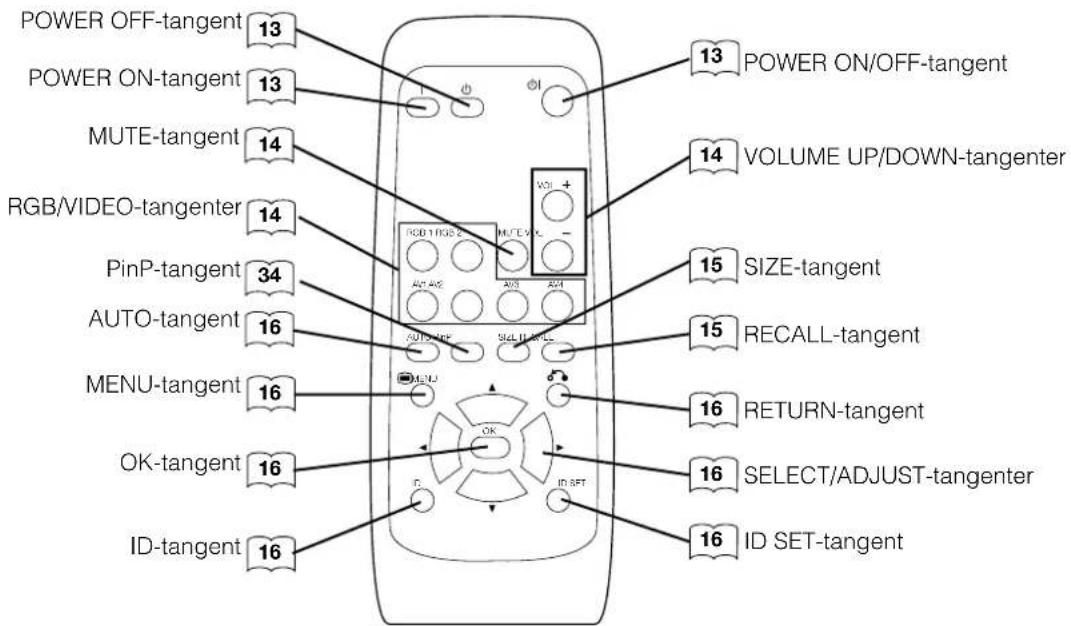
Lägga i batterier
1. Oppna batteriluckan.
INSTALLATIONSANVISNINGAR (forts.)
INSTALLATIONSANVISNINGAR (forts.)
Ansluta nätkabeln
ÖVRIGA FUNKTIONER (forts.)
Signalkontroll
ÖVRIGA FUNKTIONER (forts.)
VäljaDVD-spelare
[C14:9L]y[14:9Zoom]-16a+16
| Principal Auxiliar ○ |
4 imagenes
| Terminal de entrada AV1~AV4 AV1 | AV2 RGB1 RGB2 | TELE TEXT | |||||||||
| Auxiliar Principal | PAL SECAM | NTSC3,58 NTSC4,43 | 576i 576p | 480i 480p | 1080i/50 | 1080i/60 7 | 20p/60 ST | TB | Componente | ||
| AV1 ~AV4 | PAL, SECAM | ○ | ○ | ||||||||
| NTSC3,58/4,43 | ○ | ○ | |||||||||
| AV1 AV2 | 576i, 576p | ○ | ○ | ||||||||
| 480i, 480p | ○ | ○ | |||||||||
| 1080i/50 | ○ | ○ | |||||||||
| 1080i/60 | ○ | ○ | |||||||||
| 720p/60 | ○ | ○ | |||||||||
| RGB1 | STB | ||||||||||
| RGB2 | Componente | ○ | ○ | ||||||||
(Disponible)
| Principal | Auxiliar 1 |
| Auxiliar 2 | |
| Auxiliar 3 |