TC2CTL2 - Remote control VISION - Free user manual and instructions
Find the device manual for free TC2CTL2 VISION in PDF.
| Product Type | Infrared control module |
| Brand | Vision |
| Model | TC2CTL2 |
| Dimensions (L x W x H) | 71 × 42 × 31 mm |
| Weight | 63 g |
| Color | White |
| Power Supply | CR2450 3 V lithium battery or optional mains adapter |
| Power Consumption | Standby ≤ 5 µA, Send ≤ 20 mA, Copy ≤ 10 mA |
| Main Functions | Programmable IR control, up to 4 codes per input button, 3 codes per power button, code copying between modules |
| Number of Buttons | 9 modular function buttons (power, volume, input) |
| IR Range | Up to 10 m with included IR Blaster |
| Care and Cleaning | Clean with a soft, dry cloth. Do not use abrasive products. Avoid humidity and heat sources. |
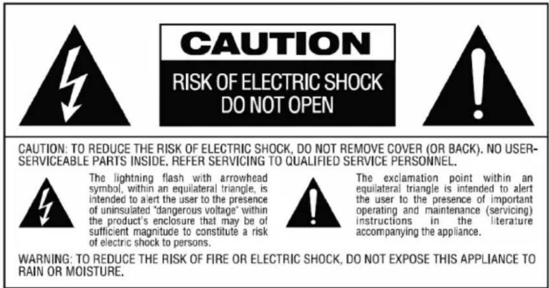
| Safety | Risk of electric shock: do not open. Do not expose to rain or moisture. Use only with recommended power supply. |
| Spare Parts and Repairability | Replaceable CR2450 battery, included IR Blasters (1 with 10 m cable, 2 without cable), optional extension cables. The product contains no user-serviceable parts. |
| Warranty | 2 years from purchase date |
| Compliance | RoHS and WEEE |
| Included Accessories | 26 interchangeable keycaps, single Techconnect back box, single Techconnect frame, 1 IR Blaster with 10 m cable, 2 IR Blasters without cable, CR2450 3 V lithium battery |
Frequently Asked Questions - TC2CTL2 VISION
User questions about TC2CTL2 VISION
0 question about this device. Answer the ones you know or ask your own.
Ask a new question about this device
Download the instructions for your Remote control in PDF format for free! Find your manual TC2CTL2 - VISION and take your electronic device back in hand. On this page are published all the documents necessary for the use of your device. TC2CTL2 by VISION.
USER MANUAL TC2CTL2 VISION
Congratulations on your choice of the Vision Techconnect IR Control? Module. In order to obtain the best performance please be sure to read this owner's manual and use your product only in accordance with the instructions. An electronic version of this manual and further information can be found on www.visionaudiovisual.com
CONFORMITY
The product described in this owners manual is in compliance with RoHS (EU directive 2002/95/EC), and WEEE (EU directive 2002/96/EC) standards. Certificates including SGS reports are available on request. This product should be returned to the place of purchase at the end of its useful life for recycling.
WARNING
Vision is a partner in the TÜV SÜD product certification system. All applicable certification is provided by TÜV. All products are designed and imported into the EU by 'Vision' who is wholly owned by 'Computer 2000 Distribution Ltd.' Registered in England Nr. 01691472 at Hampshire House, Wade Road, Basingstoke, Hampshire RG24 8NE


PLACE OF INSTALLATION
Avoid installing your unit under the following conditions:
- Moist or humid places
- Places exposed to direct sunlight or close to heating equipment
- Extremely cold locations
- Places subject to excessive vibration or dust
Poorly ventilated places
BATTERY LIFE
This product uses a 3V Lithium CR2450 battery for long life. The battery is housed in a sealed compartment and should remain dry. If the product is installed in a humid climate you should check the battery every six months to make sure it is not damp or rusty.
An optional mains-power supply is available if you prefer to run this product from mains power. Alternately this device can share a power supply with the Techconnect Amplifier² product.
LIMITATIONS OF PRODUCT
This product has been tested with a wide range of data projectors, flat panel screens, amplifiers, and projection screens. IR standards vary so we cannot guarantee this control module will control all available products on the market. We highly recommend testing this product with all equipment to be controlled before using this product for large projects. If you do have problems please let us know so that we can improve this product.
PACKAGING
Save all packing material. It is essential for shipping in the event the unit ever needs repair.
IF ORIGINAL PACKAGING IS NOT USED TO RETURN THE UNIT TO THE SERVICE CENTRE, DAMAGE IN TRANSIT WILL NOT BE COVERED BY WARRANTY.
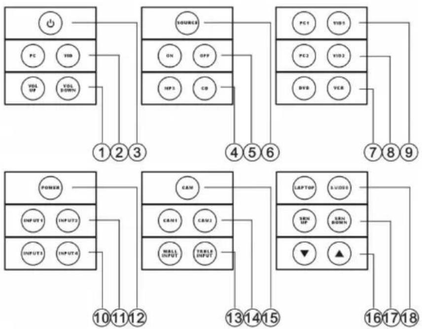
MODULAR BUTTONS INCLUDED
- VOLUME UP and DOWN Buttons
- PC and VID Buttons
- STANDBY ICON Button
- MP3 and CD Buttons
- ON and OFF Buttons
-
SOURCE Button
-
DVD and VCR Buttons
- PC2 and VID2 Buttons
- PC1 and VID1 Buttons
- INPUT3 and INPUT4 Buttons
- INPUT1 and INPUT2 Buttons
-
POWER Button
-
WALL INPUT and TABLE INPUT Buttons
- CAM1 and CAM2 Buttons
- CAM Button
- DOWN and UP ICON Buttons
- SRN UP and SRN DOWN Buttons
- LAPTOP and S-VIDEO Buttons
FRONT AND REAR CONTROL PANELS
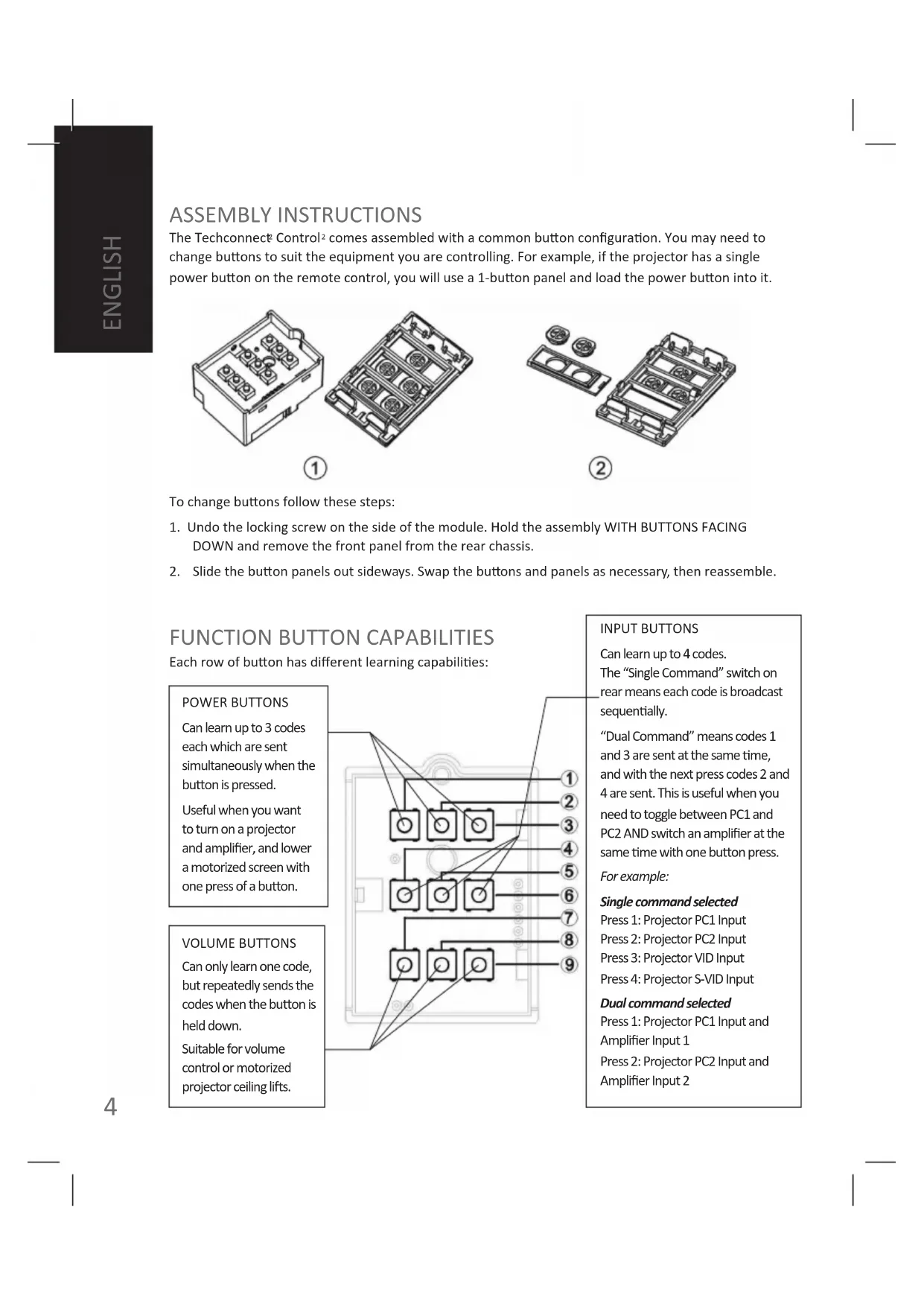
ASSEMBLY INSTRUCTIONS
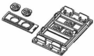
The Techconnect Control comes assembled with a common button configuration. You may need to change buttons to suit the equipment you are controlling. For example, if the projector has a single power button on the remote control, you will use a 1-button panel and load the power button into it.
①
②
To change buttons follow these steps:
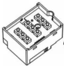
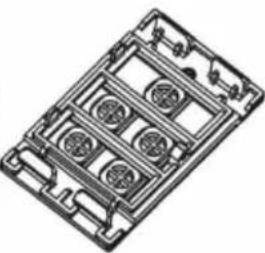
- Undo the locking screw on the side of the module. Hold the assembly WITH BUTTONS FACING DOWN and remove the front panel from the rear chassis.
- Slide the button panels out sideways. Swap the buttons and panels as necessary, then reassemble.
FUNCTION BUTTON CAPABILITIES
Each row of button has different learning capabilities:
POWER BUTTONS
Can learn up to 3 codes each which are sent simultaneously when the button is pressed.
Useful when you want to turn on a projector and amplifier, and lower a motorized screen with one press of a button.
VOLUME BUTTONS
Can only learn one code, but repeatedly sends the codes when the button is held down.
Suitable for volume control or motorized projector ceiling lifts.
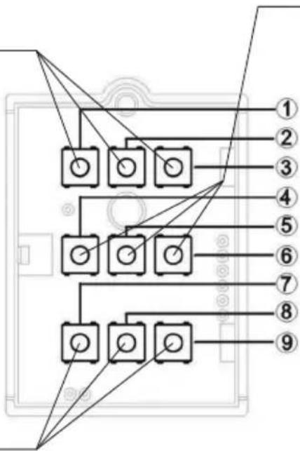
INPUT BUTTONS
Can learn up to 4 codes.
The "Single Command" switch on rear means each code is broadcast sequentially.
"Dual Command" means codes 1 and 3 are sent at the same time, and with the next press codes 2 and 4 are sent. This is useful when you need to toggle between PC1 and PC2 AND switch an amplifier at the same time with one button press.
For example:
Single command selected
Press 1: Projector PC1 Input
Press 2: Projector PC2 Input
Press 3: Projector VID Input
Press 4: Projector S-VID Input
Dual command selected
Press 1: Projector PC1 Input and Amplifier Input 1
Press 2: Projector PC2 Input and Amplifier Input 2
PROGRAMMING
1. POWER FUNCTION BUTTON PROGRAMMING
The POWER BUTTONS (1/2/3) can learn up to three codes each and send them simultaneously. Use this when you want to turn up to three devices on or off at once. The position of the Single/Dual Command switch has no affect on these buttons.
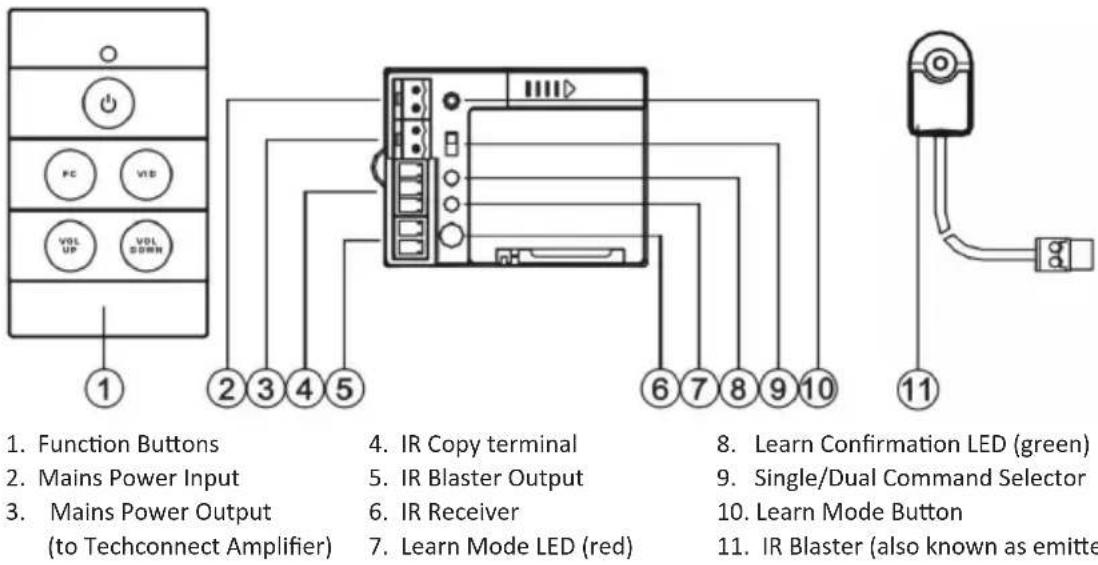
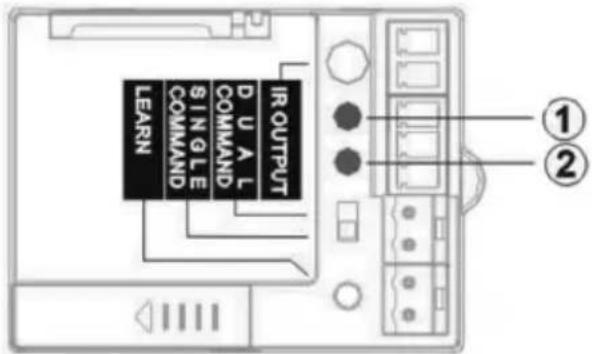
a) Press and release LEARN button. The RED LED on the REAR panel will light and stay on indicating that the device is in "Learn Mode". Note: If there is no activity for 30 seconds, the device will go back to "Normal Mode".
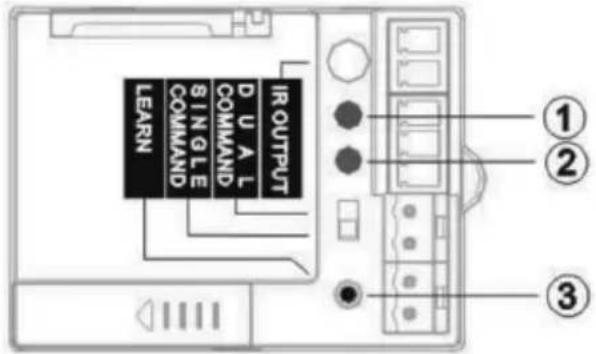
(1) Red LED - indicates learn mode
(2) Green LED - flashes to indicate successful learning
(3) LEARN Button - used to enter "Learn Mode"
b) Press and hold FUNCTION button on the front panel you want to program. The LED on the FRONT panel will cycle through three colours: RED > ORANGE > GREEN. Each colour represents one of the three codes that button can learn.
NOTE: PROJECTOR OFF CODE SHOULD BE PROGRAMMED TO GREEN. The GREEN code for buttons 2 and 3 will always be broadcast twice automatically. This is for projectors which require a second confirmation code to be sent to turn off.
c) Release the button when the desired colour is showing on the front LED. Aim the original remote control at the IR RECEIVER on the rear of the module and press and hold the function button on the remote control. Release only after the GREEN LED on the REAR has flashed three times.
The Control ^2 will automatically switch from "Learn Mode" back to "Normal Mode".
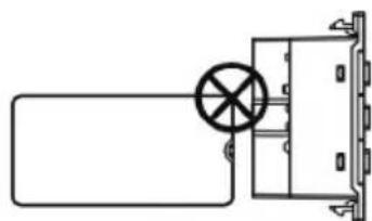
Note: Hold the original remote control 30-50mm away from the rear of the module, and at 90^ to the IR Receiver. Programming under fluorescent lights which can interfere with the ability to learn IR codes.
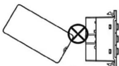
①
②
- Incorrect angle
- Too close
If the red LED flashes multiple times and does not turn off the device has not learnt the code and it will stay in "Learn Mode". Try again.
Repeat steps a-c to program the other colours for each button.
2. INPUT FUNCTION BUTTON PROGRAMMING
The INPUT BUTTONS (4/5/6) can learn four codes each and send them one after the other, or two at a time.
Before you start programming you should select "Single Command" or "Dual Command" using the switch on the rear.
a) SINGLE COMMAND
Empty memory positions will be skipped. It will cycle sequentially through the codes you have programmed into it.
| Example 1: If it has been taught four codes Example 2: If it has been taught two codes | |
| Press 1: Input 1 | Press 1: Input 1 |
| Press 2: Input 2 | Press 2: Input 2 |
| Press 3: Input 3 | Press 3: Input 1... etc |
| Press 4: Input 4 | |
| Press 5: Input 1... etc | |
b) DUAL COMMAND
The first two codes are for the display device, and the second two codes are for the amplifier.
This is because the ControlP broadcasts codes in the following order:
Press 1: Broadcasts code 1 first, then code 3 a second later.
Press 2: Broadcasts code 2 first, then code 4 a second later.... etc
To program these buttons follow the same steps as for the POWER BUTTONS. The LED on the front panel will cycle through RED > ORANGE > GREEN > ORANGE >, each representing the four codes each button can learn.
3. VOLUME FUNCTION BUTTON PROGRAMMING
The VOLUME BUTTONS (7/8/9) can only learn one code each. They are preset to send out the code repeatedly if the button is held down. The position of the Single/Dual Command switch has no affect on these buttons.
The process for programming these buttons is different to the other buttons:
a) Press and release LEARN button. The RED LED on the REAR panel will light and stay on indicating that the device is in "Learn Mode".
b) Press and release FUNCTION button you want to assign the code to on the front panel. The RED LED on the REAR panel will flash once then it will stay on.
c) Aim the original remote control at the IR RECEIVER on the rear of the module and press and hold the function button on the remote control. Release only after the GREEN LED on the REAR has flashed three times. The device will automatically switch to "Normal Mode".
If the red light flashes it means the code has not been learnt successfully. Repeat steps b and c again.
4. DELETING CODES
If you want delete a code that you've programmed to a button follow these steps:
a) Press and release learn button (rear red light comes on and stays on)
b) Press and hold the appropriate FUNCTION button on front panel until the front LED is the colour representing the code you wish to delete then release.
c) Press and hold buttons 7 and 9 until the front LED turns off.
The code has been deleted and the Control reverts back to "normal mode".
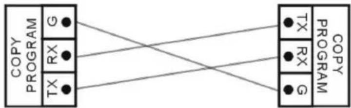
COPYING CODES TO MULTIPLE DEVICES
The codes from one Techconnect ^2 Control ^2 (master) can copied to other Control ^2 modules (slaves).
- Use a cable to connect the COPY terminals of the MASTER and SLAVE together as shown:
- Press and hold LEARN button on the master until ONLY the GREEN LED on the REAR lights.
- Press and hold LEARN button on the slave until the RED AND GREEN LEDs on the REAR both light.
(1) Red LED
(2) Green LED
- Press any FUNCTION button on the front panel of the "master". The RED LED on the front panels of the master AND slave modules will both flash and the codes will copy. This will normally take 10 seconds. When finished the green LEDs of the master and slave units will flash three times simultaneously, then turn off. The devices will automatically switch to "Normal Mode". If unsuccessful the red LEDs of the master and slave modules will flash at the same time, then turn off. Try again.
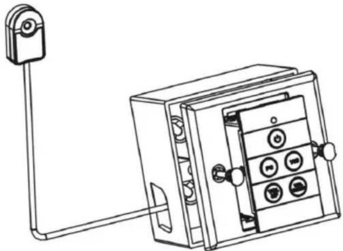
INSTALLATION
The Techconnect? Control comes with a single-gang backbox and surround. In this example we show how to mount it to the wall using these parts, but you could also integrate it into a double-gang Techconnect? surround with other Techconnect modules if you prefer.
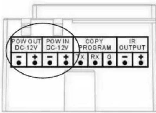
- Install the module into the Techconnect ^2 surround as shown. Plug in the IR Blaster cable provided and mains power (if required). The Control ^2 module can share the power supply provided with a Techconnect Amplifier ^2 module. In this case an included cable connects from the power output of the Control ^2 module to the power input of the Amplifier ^2 module.
NOTE I: IF THE BATTERY IS REMOVED OR POWER DISCONNECTED THE PROGRAMMED CODES WILL NOT BE LOST. THEY ARE SAVED INDEFINETELY.
NOTE II: SHARING POWER IS ONLY POSSIBLE WITH THE VERSION OF THE TECHCONNECT AMP WHICH SHIPS WITH AN IR REMOTE CONTROL.
NOTE III: TAKE CARE TO CONNECT THE POWER POLARITY CORRECTLY. INCORRECT CONNECTION WILL RESULT IN FAILURE OF PRODUCT WHICH WILL NOT BE COVERED BY WARRANTY.
- Route the included IR Blaster cable to the projector. This cable can be shortened or lengthened easily at the Phoenix connector end. The IR emitter should be positioned over or near the IR receiver on the projector as shown below. Option (1) is most effective as the IR signal can be weakened by direct sunlight or fluorescent lights.
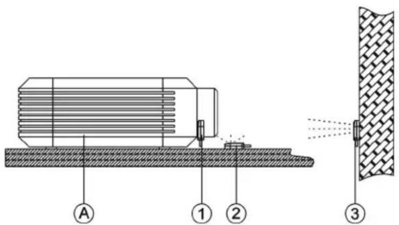
A. Projector
- Stuck on the IR receiver built in to the projector
- Sitting near the IR receiver
- Attached to a wall directly facing the IR receiver
Two additional IR emitters are included if you need to control other equipment such as amplifiers or motorized projection screens. To use these you will need additional Techconnect minijack cables available in 10, 15, or 20m lengths. Termination of these Techconnect minijack cables is as follows:
White: -
Red: +
Shield: unterminated
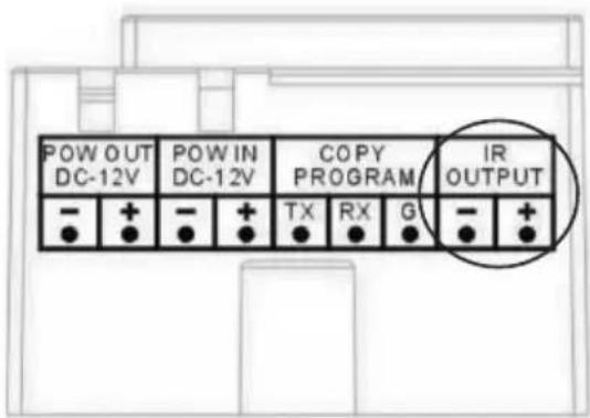
Multiple IR Blaster cables should be connected to the same IR OUTPUT phoenix connector on the rear panel of the Control2.
SPECIFICATIONS
- Power Consumption:
Static: <=5uA /Sending: <=20mA /Copying: <=10mA - Dimensions: 71 × 42 × 31 mm
Weight: 63 grams
Colour:White
Note: Because we are committed to improving our products, the details above may change without prior warning.
ACCESSIONS INCLUDED
26 x Interchangeable buttons
1 x Single-Gang Techconnect Backbox
1 x Single-Gang Techconnect Surround
1 x IR Blaster with 10m cable
2 x IR Blaster without cable
1 x 3V Lithium CR2450 Battery
TROUBLESHOOTING
If your system is not operating properly, please refer to the following information. If the problem persists, disconnect from power and contact your AV reseller immediately.
| Problem Correction | |
| No LED when front buttons pressed · Replace battery · Check mains power connection (if present) · Make sure codes have been learnt | |
| Module fails to learn the code · Make sure the original remote is 30-50mm away from the receiver on the rear of the module, and at 90 degrees. · Make sure the original remote has fresh batteries. · Hold down the button on the original remote for longer until after the green LED lights on the Module. | |
| Module learns code but doesn't control the projector | · Re-program the buttons. · Re-position the IR blaster. · Check IR blaster cable to make sure it hasn't been damaged during installation. |
WARRANTY
This product comes with a 2-year return to base warranty, effective from the date of purchase. This warranty applies only to the original purchaser and is not transferable. For the avoidance of doubt, this will be taken from the information held by the appointed national distributor at the point of sale. If the product is DOA (dead on arrival), you have 21 days from purchase date to notify the national distributor via your AV reseller. The liability of the manufacturer and its appointed service company is limited to the cost of repair and/or replacement of the faulty unit under warranty, except for death or injury (EU85/374/EEC). This warranty protects you against the following:
- Failure of any components.
- Damage when the product is first removed from its packaging if reported within 24 hours of purchase.
If you find you do have a problem with this product, you should contact the AV reseller you purchased this product from. The original purchaser is responsible for shipment of the product to the manufacturer's appointed service centre for repair. We will endeavour to return repaired units within 5 working days, however this may not always be possible, in which case it will be returned as soon as practicably possible. In line with our WEEE commitments, the manufacturer endeavours to replace the faulty parts of the product rather than replacing the whole unit. This warranty does not protect this product against faults caused by abuse, misuse, incorrect installation, unstable or faulty power input, which might be caused by ignoring the guidelines set out in this manual.