SP5000 - Speaker VISION - Free user manual and instructions
Find the device manual for free SP5000 VISION in PDF.
| Brand | Vision |
| Model | SP5000 |
| Product type | Passive wall speaker |
| Dimensions (per chassis) | 520 x 170 x 130 mm (H x D x W) |
| Weight (pair) | 6 kg |
| Color | Silver |
| Frequency response | 90 Hz - 20 kHz |
| Power handling (per speaker) | 20 W RMS |
| Speakers | Tweeter: 1 inch silk; Woofer: 3.5 inches |
| Nominal impedance | 8 ohms |
| Sensitivity | 86 dB |
| Power supply (USB decoder) | DC 12 V, 0.5 A |
| Included accessories | 2 wall mounts, 1 security cable, 1 USB cable 200 mm, 1 power cord, 10 blank Techconnect modules, 6 cable outlet covers |
| Warranty | 2 years, return to workshop |
| Care and cleaning | Clean with a dry cloth; do not use liquid products; avoid moisture and dust. |
| Safety | Do not expose to water; do not pull on the power cord; unplug before moving. |
| Spare parts and repairability | Internal components are not user-serviceable. Contact the retailer for any repairs. |
Frequently Asked Questions - SP5000 VISION
User questions about SP5000 VISION
0 question about this device. Answer the ones you know or ask your own.
Ask a new question about this device
Download the instructions for your Speaker in PDF format for free! Find your manual SP5000 - VISION and take your electronic device back in hand. On this page are published all the documents necessary for the use of your device. SP5000 by VISION.
USER MANUAL SP5000 VISION
Congratulations on your choice of the Vision SP-5000. In order to obtain the best performance please be sure to read this owner's manual and use your product only in accordance with the instructions. An electronic version of this manual and further information can be found on www.visionaudiovisual.com
CONFORMITY
The product described in this owners manual is in compliance with RoHS (EU directive 2002/95/EC), and WEEE (EU directive 2002/96/EC) standards. Certificates including SGS reports are available on request. This product should be returned to the place of purchase at the end of its useful life for recycling.
WARNINGS
natural_image
Black triangular warning symbol with a white lightning bolt inside, indicating electrical hazard (no text)
text_image
CAUTION RISK OF ELECTRIC SHOCK DO NOT OPEN
natural_image
Black triangular warning symbol with exclamation mark (no text or numbers)CAUTION: TO REDUCE THE RISK OF ELECTRIC SHOCK, DO NOT REMOVE COVER (OR BACK). NO USER-SERVICEABLE PARTS INSIDE. REFER SERVICING TO QUALIFIED SERVICE PERSONNEL.
The lightning flash with arrowhead symbol, within an equilateral triangle, is intended to alert the user to the presence of uninsulated "dangerous voltage" within the product's enclosure that may be of sufficient magnitude to constitute a risk of electric shock to persons.

The exclamation point within an equilateral triangle is intended to alert the user to the presence of important operating and maintenance (servicing) instructions in the literature accompanying the appliance.
WARNING: TO REDUCE THE RISK OF FIRE OR ELECTRIC SHOCK, DO NOT EXPOSE THIS APPLIANCE TO RAIN OR MOISTURE.
Vision is a partner in the TÜV SÜD product certification system. All applicable certification is provided by TÜV. All products are designed and imported into the EU by 'Vision' who is wholly owned by Azlan Logistics Ltd, Registered in England Nr. 04625566 at 'Lion House, Pioneer Business Park, Clifton Moor, York, YO30 4GH'

text_image
ReHS WEE/AB0047SY TUV SUD CEUSE ONLY DOMESTIC AC OUTLETS
Connecting the unit to an outlet supplying a higher voltage may create a fire hazard.
HANDLE THE POWER CORD WITH CARE
Do not disconnect the plug from the AC outlet by pulling the cord; always pull the plug itself. Pulling the cord may damage it. If you do not intend to use your unit for any considerable length of time, unplug the unit. Do not place furniture or other heavy objects on the cord, and try to avoid dropping heavy objects on it. Do not tie a knot in the power cord. Not only could the cord be damaged, but a short circuit could also be caused with a consequent fire hazard.
PLACE OF INSTALLATION
Avoid installing this product under the following conditions:
- Moist or humid places
- Places exposed to direct sunlight or close to heating equipment
• Extremely cold locations - Places subject to excessive vibration or dust
- Poorly ventilated places
Do not expose this product to dripping or splashing. DO NOT PLACE OBJECTS FILLED WITH LIQUIDS ON OR NEAR THIS PRODUCT!
MOVING THE UNIT
Before moving the unit, be sure to pull out the power cord from the AC outlet and disconnect the interconnection cords with other units.
WARNING SIGNS
If you detect an abnormal smell or smoke, turn this product off immediately and unplug the power cord. Contact your reseller or Vision.
PACKAGING
Save all packing material. It is essential for shipping in the event the unit ever needs repair. IF ORIGINAL PACKAGING IS NOT USED TO RETURN THE UNIT TO THE SERVICE CENTRE, DAMAGE IN TRANSIT WILL NOT BE COVERED BY WARRANTY.
POWER HANDLING
The power rating given denotes the “power handling” of the speaker (not power output). These speakers are rated to accept up to 20 watts RMS each.
Care should be taken to use an amplifier which has a power output of 10-100w RMS. An amplifier which is too small may send loudspeakers a distorted signal which is causes damage very quickly and WITHOUT any obvious signs such as audible distortion, whereas an amplifier which is too large may send a signal which is too powerful and will cause damage if sustained over a period of time.
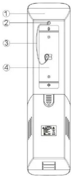
FRONT
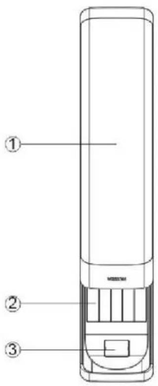
text_image
Technical diagram of a vertical cylindrical device with numbered components labeled ①, ②, and ③.
text_image
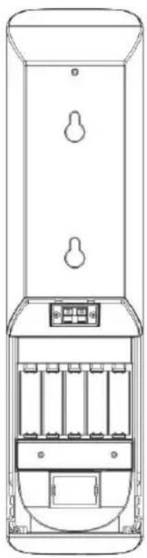
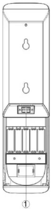
1. Sliding 2. Tech 3. Cable 4. Speak- Sliding grille
- Techconnect modules
- Cable exit cover
- Speaker Chassis
REAR

text_image
Technical diagram of a device with numbered parts labeled 1 to 4, showing internal components and control panel.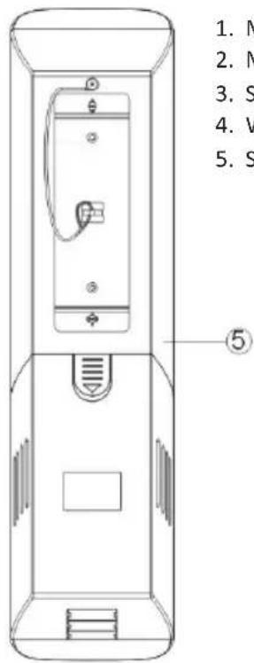
text_image
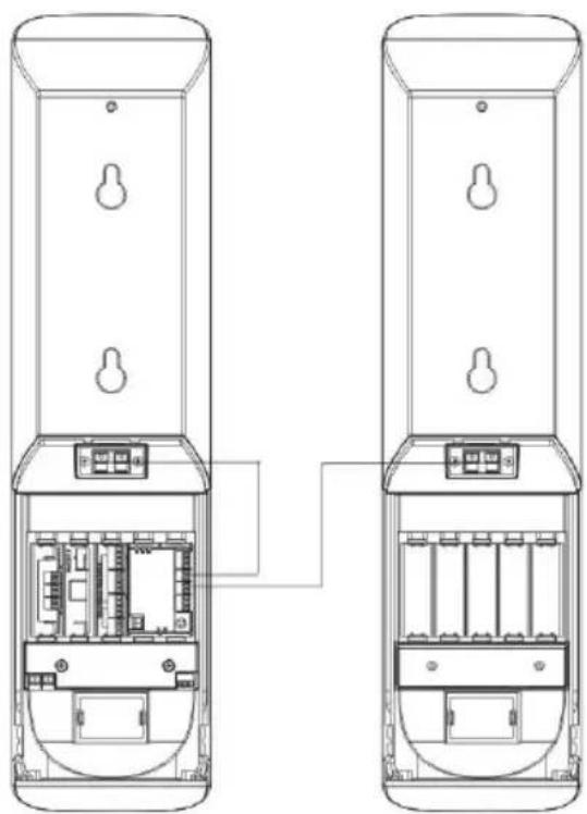
1. M 2. N 3. S 4. V 5. S ⑤- Master speaker
- M4 × 8 safety cable screw
- Safety cable
- Wall brackets
- Slave speaker
INSTALLATION INSTRUCTIONS
natural_image
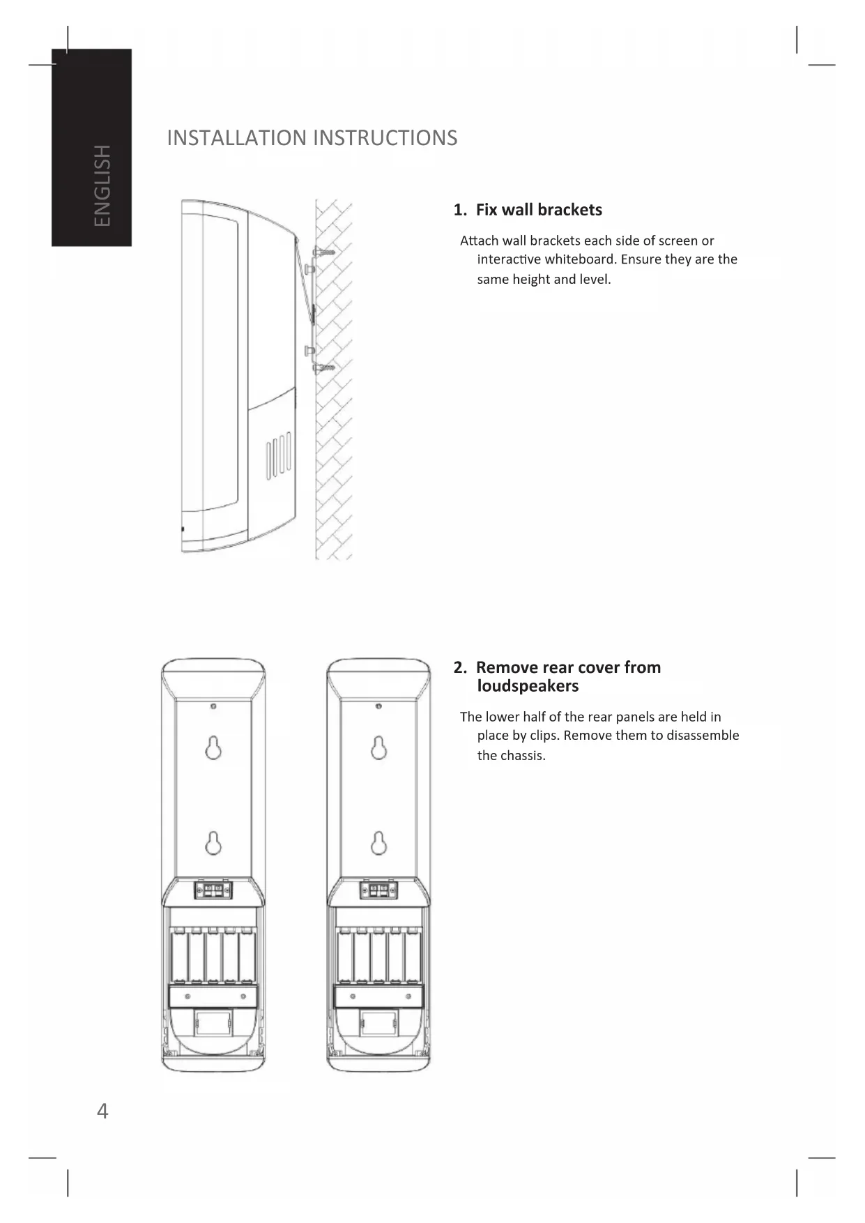
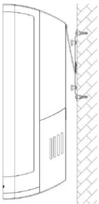
Technical line drawing of a door panel with a wall-mounted bracket and hatched material (no text or symbols)1. Fix wall brackets
Attach wall brackets each side of screen or interactive whiteboard. Ensure they are the same height and level.
natural_image
Technical line drawing of a vertical mechanical device with internal compartments and mounting holes (no text or symbols)
natural_image
Technical line drawing of a vertical cylindrical device with internal compartments and mounting holes (no text or symbols)2. Remove rear cover from loudspeakers
The lower half of the rear panels are held in place by clips. Remove them to disassemble the chassis.
natural_image
Technical line drawing of a vertical cylindrical device with internal compartments and mounting holes (no text or symbols)
natural_image
Technical line drawing of a vertical cylindrical device with internal compartments and mounting holes (no text or symbols)3. Connect cables to the loudspeakers
A) NOT USING TECHCONNECT MODULES
If using separate connectivity faceplate and amplifier then only speaker cable needs to be connected to the bare-wire terminals shown (1, 2).
natural_image
Technical line drawing of two vertical electrical enclosure units with internal compartments and mounting holes (no text or symbols)B) USING TECHCONNECT MODULES
If installing with Techconnect modules, then follow these steps:
Step 1:
Install required Techconnect modules.
Step 2:
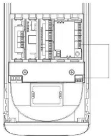
Connect audio from rear of connectivity modules to inputs on rear of Techconnect Amplifier.
Step 3:
Connect the loudspeaker outputs of the amplifier module to the bare-wire speaker terminals as shown.
text_image
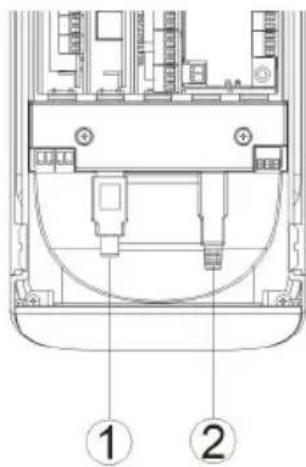
Technical diagram of a device rear panel with labeled components and numbered parts4. Using Audio-over-USB decoder
To install these loudspeakers so that a PC will recognise it as an audio output device follow these steps:
Step 1: Connect USB to the decoder.
If using a Techconnect connectivity faceplate USB from the PC will plug into the front of the USB-B module. Then use the short USB cable included to connect from the rear of the USB-B module into the decoder (2).
The decoder has a USB-A connector which (1) is connected to an interactive whiteboard.
natural_image
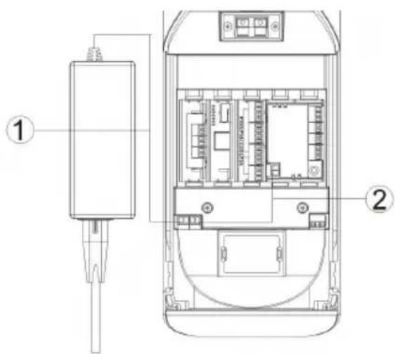
Architectural floor plan of a mobile phone showing internal compartments and ventilation slots (no text or labels)Step 2: Connect audio output (green connector) on the decoder to the input on the amplifier as shown.
NOTE: The USB decodes outputs line-level signal which can be input into any low impedance amplifier
text_image
Technical diagram of an electronic device showing internal components and labeled parts, including a connector and terminal block.Step 3: Connect power to power input (black connector) on decoder.
NOTE: Power is ONLY required if the USB signal continues on to another device such as an interactive whiteboard. If no other device is connected then the power carried on the USB input cable is sufficient to power the decoder.
If using a Techconnect amplifier plug the power supply into the decoder (1), use power patch cable provided to connect the decoder power output connector to the Techconnect Amplifier module power input (2).
If you are not using a Techconnect Amplifier then spare power supplies for the Techconnect Control are available which will also work. The power requirement is DC, 12V, 0.5A.
SAFETY WARNING: Ensure polarity is connected correctly. Incorrect connection can damage the product and is not covered by warranty.
5. Replace the rear cover and hang on bracket
Re-attach the rear covers, and hang in place. Cable exit covers are included which allow variable sized exit holes.
TROUBLESHOOTING
If your system is not operating properly, please refer to the following information. If the problem persists, disconnect from power and contact your AV reseller immediately.
| Problem Correction | |
| Sounds Hollow /No Bass | Check that you've connector the speaker cable polarity positive-to-positive and negative-to-negative. |
| Distortion /No treble | Distortion can be caused by poor gain structure. Ensure the gain (volume) on your source device is at 100%, and turn the amplifier down.If the problem still persists determine if both speakers are distorting the sound. If it is only one it is likely you have a damaged driver and you should contact your AV reseller immediately. If both are outputting distorted sound the problem is more likely to lie with the amplifier. |
| No sound /Sound only coming outon one side | You should take these steps to narrow down where the problem lies:Step 1:Bypass the faceplate inputs by plugging an audio source directly into the amplifier. In the case of the Techconnect Amplifier for example plug in iPod into the front input, ensuring that the iPod is turned to full volume.If the problem has gone away the fault is with your input connections.Step 2:If the problem still persists then swap the Left and Right output connectors on the amplifier.a) If only the left speaker was working, and now only the right speaker is working, you know the speakers both work and the problem is with the amplifier.b) If only the left speaker was working, and after switching the left speaker is still the only one working, then you know the problem is with the right speaker. |
SPECIFICATIONS
Product Dimensions (single chassis):
520 x 170 x 130mm (h x d x w)
Product Weight (pair): 6kg
Colour: Silver
Technical Details:
Frequency Response: 90Hz-20KHz
Power handling: 20 watts RMS
Tweeter: 1" silk
Woofer: 3.5"
Nominal impedance: 8 ohms
Sensitivity: 86dB
USB decoder power requirements: DC, 12V, 0.5A
ACCESSORIES INCLUDED
1 x USB Patch cable 200mm long•
1 x Power Patch cable•
10 x Techconnect Blank modules•
6 x Cable Exit Covers•
2 x Wall Brackets•
1 x Safety Cable•
Note: Because we are committed to improving our products, the details above may change without prior warning.
WARRANTY
This product comes with a 2-year return to base warranty, effective from the date of purchase. This warranty applies only to the original purchaser and is not transferable. For the avoidance of doubt, this will be taken from the information held by the appointed national distributor at the point of sale. If the product is DOA (dead on arrival), you have 21 days from purchase date to notify the national distributor via your AV reseller. The liability of the manufacturer and its appointed service company is limited to the cost of repair and/or replacement of the faulty unit under warranty, except for death or injury (EU85/374/EEC). This warranty protects you against the following:
- Failure of any components, including the power supply.
- Damage when the product is first removed from its packaging if reported within 24 hours of purchase.
If you find you do have a problem with this product, you should contact the AV reseller you purchased this product from. The original purchaser is responsible for shipment of the product to the manufacturer's appointed service centre for repair.
We will endeavour to return repaired units within 5 working days, however this may not always be possible, in which case it will be returned as soon as practicably possible. In line with our WEEE commitments, the manufacturer endeavours to replace the faulty parts of the product rather than replacing the whole unit. This warranty does not protect this product against faults caused by abuse, misuse, incorrect installation, unstable or faulty power input, which might be caused by ignoring the guidelines set out in this manual.
MANUEL DE L'UTILISATEUR SP-5000
natural_image
Black triangular warning symbol with a lightning bolt inside, indicating electrical hazard (no text)
text_image
CAUTION RISK OF ELECTRIC SHOCK DO NOT OPEN
natural_image
Black triangular warning symbol with exclamation mark (no text or numbers)CAUTION: TO REDUCE THE RISK OF ELECTRIC SHOCK, DO NOT REMOVE COVER (OR BACK). NO USER-SERVICEABLE PARTS INSIDE. REFER SERVICING TO QUALIFIED SERVICE PERSONNEL.
The lightning flash with arrowhead symbol, within an equilateral triangle, is intended to alert the user to the presence of uninsulated "dangerous voltage" within the product's enclosure that may be of sufficient magnitude to constitute a risk of electric shock to persons.

The exclamation point within an equilateral triangle is intended to alert the user to the presence of important operating and maintenance (servicing) instructions in the literature accompanying the appliance.
WARNING: TO REDUCE THE RISK OF FIRE OR ELECTRIC SHOCK, DO NOT EXPOSE THIS APPLIANCE TO RAIN OR MOISTURE.
text_image
ReHS No. 1 TUV SUO CEUTILISEZ UNIQUEMENT DES PRISES DE COURANT CA DOMESTIQUES.
text_image
Technical diagram of a vertical cylindrical device with numbered components labeled ①, ②, and ③.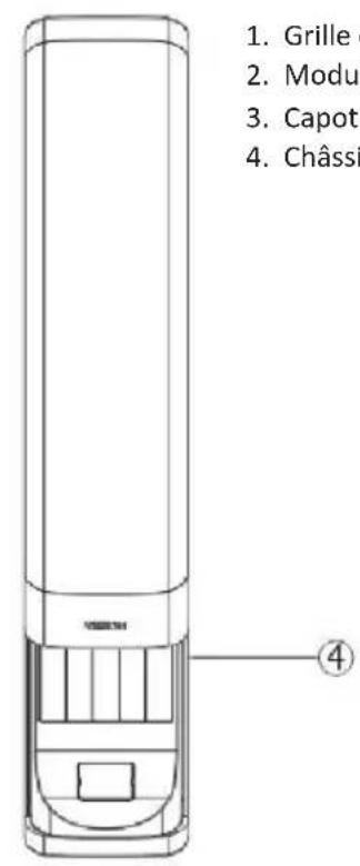
text_image
1. Grille 2. Modu 3. Capot 4. Châssir ④text_image
Diagram of a device with numbered parts labeled 1 to 4, showing internal components and a control panel.
text_image
1. H 2. V 3. C 4. S 5. H ⑤natural_image
Technical line drawing of a door panel with a wall-mounted bracket and hatched material (no text or symbols)natural_image
Technical line drawing of a vertical mechanical device with internal compartments and mounting holes (no text or symbols)
natural_image
Technical line drawing of a vertical cylindrical device with internal compartments and mounting holes (no text or symbols)natural_image
Technical line drawing of a vertical cylindrical device with internal compartments and mounting holes (no text or symbols)
natural_image
Technical line drawing of a vertical cylindrical device with internal compartments and mounting holes (no text or symbols)natural_image
Technical line drawing of two vertical electrical enclosure units with internal compartments and mounting holes (no text or symbols)B) AVEC UTILISATION DE MODULES TECHCONNECT
text_image
Technical diagram of a device rear panel with labeled components and numbered partsnatural_image
Architectural floor plan of a mobile phone showing internal seating and ventilation duct (no text or labels)text_image
Technical diagram of an electronic device showing internal components and labeled parts, including a connector and terminal block.natural_image
Black triangular warning symbol with a white lightning bolt inside, indicating electrical hazard (no text)
text_image
CAUTION RISK OF ELECTRIC SHOCK DO NOT OPEN
natural_image
Black triangular warning symbol with exclamation mark (no text or numbers)CAUTION: TO REDUCE THE RISK OF ELECTRIC SHOCK, DO NOT REMOVE COVER (OR BACK). NO USER-SERVICEABLE PARTS INSIDE. REFER SERVICING TO QUALIFIED SERVICE PERSONNEL.

The lightning flash with arrowhead symbol, within an equilateral triangle, is intended to alert the user to the presence of uninsulated "dangerous voltage" within the product's enclosure that may be of sufficient magnitude to constitute a risk of electric shock to persons.

The exclamation point within an equilateral triangle is intended to alert the user to the presence of important operating and maintenance (servicing) instructions in the literature accompanying the appliance.
WARNING: TO REDUCE THE RISK OF FIRE OR ELECTRIC SHOCK, DO NOT EXPOSE THIS APPLIANCE TO RAIN OR MOISTURE.
text_image
ReHS TUV SUO CEUTILIZAR SOLO SALIDAS AC DOMÉSTICAS
natural_image
Technical line drawing of a door panel with a wall-mounted bracket and hatched material (no text or symbols)1. Abrazaderas fijas de pared
natural_image
Technical line drawing of a vertical mechanical device with internal compartments and mounting holes (no text or symbols)
natural_image
Technical line drawing of a vertical cylindrical device with internal compartments and mounting holes (no text or symbols)natural_image
Technical line drawing of a vertical cylindrical device with internal compartments and mounting holes (no text or symbols)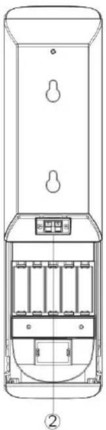
natural_image
Technical line drawing of a vertical cylindrical device with internal compartments and mounting holes (no text or symbols)natural_image
Technical line drawing of two vertical electrical enclosure units with internal compartments and mounting holes (no text or symbols)text_image
Technical diagram of a device rear panel with labeled components and numbered partsnatural_image
Architectural floor plan of a mobile phone showing internal compartments and seating areas (no text or labels)text_image
Technical diagram of an electronic device showing internal components and labeled parts, including a connector and terminal block.natural_image
Black triangular warning symbol with a white lightning bolt inside, indicating electrical hazard (no text)
text_image
CAUTION RISK OF ELECTRIC SHOCK DO NOT OPEN
natural_image
Black triangular warning symbol with exclamation mark (no text or numbers)CAUTION: TO REDUCE THE RISK OF ELECTRIC SHOCK, DO NOT REMOVE COVER (OR BACK). NO USER-SERVICEABLE PARTS INSIDE. REFER SERVICING TO QUALIFIED SERVICE PERSONNEL.

The lightning flash with arrowhead symbol, within an equilateral triangle, is intended to alert the user to the presence of uninsulated "dangerous voltage" within the product's enclosure that may be of sufficient magnitude to constitute a risk of electric shock to persons.
The exclamation point within an equilateral triangle is intended to alert the user to the presence of important operating and maintenance (servicing) instructions in the literature accompanying the appliance.
WARNING: TO REDUCE THE RISK OF FIRE OR ELECTRIC SHOCK, DO NOT EXPOSE THIS APPLIANCE TO RAIN OR MOISTURE.
text_image
ReHS WEE/AB0047SY TUV SUD CEGEBRUIK ALLEEN STOPCONTACTEN DIE STANDAARD ZIJN VOOR UW LAND
HET APPARAAT VERPLAATSEN
text_image
Technical diagram of a vertical cylindrical device with numbered components labeled ①, ②, and ③.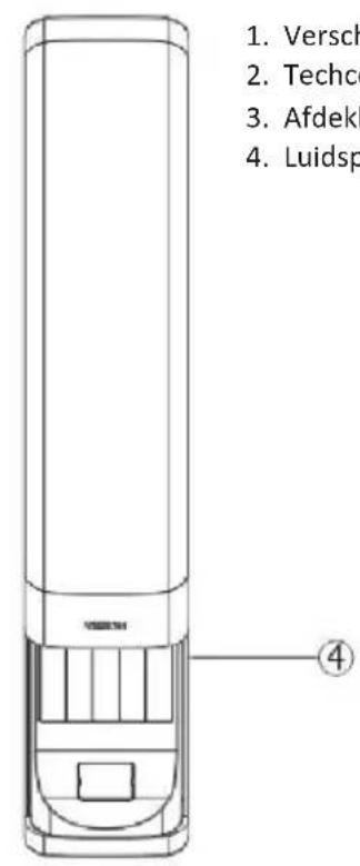
text_image
1. Versch 2. Techo 3. Afdekl 4. Luidsp ④text_image
Diagram of a device with numbered parts labeled 1 to 4, showing internal components and control buttons.
text_image
1. H 2. M bev 3. B 4. M 5. S ⑤natural_image
Technical line drawing of a door panel with a wall-mounted bracket and hatched material (no text or symbols)1. Monteren muurbeugels
natural_image
Technical line drawing of a vertical mechanical device with internal compartments and mounting holes (no text or symbols)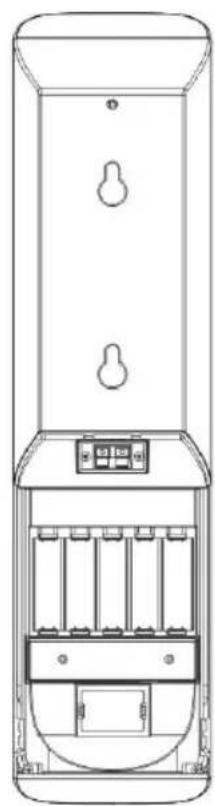
natural_image
Technical line drawing of a vertical cylindrical device with internal compartments and mounting holes (no text or symbols)natural_image
Technical line drawing of a vertical cylindrical device with internal compartments and mounting holes (no text or symbols)
natural_image
Technical line drawing of a vertical cylindrical device with internal compartments and mounting holes (no text or symbols)natural_image
Technical line drawing of two vertical electrical enclosure units with internal compartments and mounting holes (no text or symbols)B) U GEBRUIKT TECHCONNECT-MODULES
text_image
Technical diagram of a device rear panel with labeled components and numbered partsnatural_image
Architectural floor plan of a mobile phone showing internal compartments and ventilation slots (no text or labels)text_image
Technical diagram of an electronic device showing internal components and labeled parts, including a connector and terminal block.natural_image
Black triangular warning symbol with a white lightning bolt inside, indicating electrical hazard (no text)
text_image
CAUTION RISK OF ELECTRIC SHOCK DO NOT OPEN
natural_image
Black triangular warning symbol with exclamation mark (no text or numbers)CAUTION: TO REDUCE THE RISK OF ELECTRIC SHOCK, DO NOT REMOVE COVER (OR BACK). NO USER-SERVICEABLE PARTS INSIDE. REFER SERVICING TO QUALIFIED SERVICE PERSONNEL.

The lightning flash with arrowhead symbol, within an equilateral triangle, is intended to alert the user to the presence of uninsulated "dangerous voltage" within the product's enclosure that may be of sufficient magnitude to constitute a risk of electric shock to persons.

The exclamation point within an equilateral triangle is intended to alert the user to the presence of important operating and maintenance (servicing) instructions in the literature accompanying the appliance.
WARNING: TO REDUCE THE RISK OF FIRE OR ELECTRIC SHOCK, DO NOT EXPOSE THIS APPLIANCE TO RAIN OR MOISTURE.
text_image
ReHS TUV SUO CENUR ORTSÜBLICHE STECKDOSEN VERWENDEN.
text_image
Technical diagram of a vertical cylindrical device with numbered components labeled ①, ②, and ③.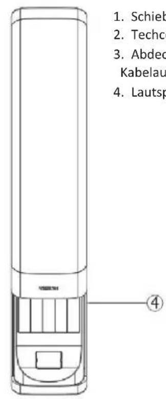
text_image
1. Schieb 2. Techo 3. Abdec Kabelau 4. Lautsptext_image
Diagram of a device with numbered parts labeled 1 to 4, showing internal components and a control panel.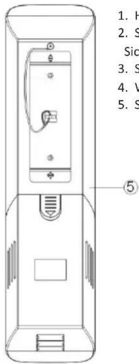
text_image
1. H 2. S Sic 3. S 4. V 5. S ⑤natural_image
Technical line drawing of a door panel with a wall-mounted bracket and hatched material (no text or symbols)natural_image
Line drawing of a vertical cylindrical device with internal compartments and mounting holes (no text or symbols)
natural_image
Technical line drawing of a vertical cylindrical device with internal compartments and mounting holes (no text or symbols)natural_image
Technical line drawing of a vertical cylindrical device with internal compartments and mounting holes (no text or symbols)
natural_image
Technical line drawing of a vertical cylindrical device with internal compartments and mounting holes (no text or symbols)natural_image
Technical line drawing of two vertical electrical enclosure units with internal compartments and mounting holes (no text or symbols)text_image
Technical diagram of a device rear panel with labeled components and numbered partsnatural_image
Architectural floor plan of a mobile phone showing internal compartments and seating areas (no text or labels)text_image
Technical diagram of a device rear panel with labeled components and internal layoutnatural_image
Black triangular warning symbol with a white lightning bolt inside, indicating electrical hazard (no text)
text_image
CAUTION RISK OF ELECTRIC SHOCK DO NOT OPEN
natural_image
Black triangular warning symbol with exclamation mark (no text or numbers)CAUTION: TO REDUCE THE RISK OF ELECTRIC SHOCK, DO NOT REMOVE COVER (OR BACK). NO USER-SERVICEABLE PARTS INSIDE. REFER SERVICING TO QUALIFIED SERVICE PERSONNEL.

The lightning flash with arrowhead symbol, within an equilateral triangle, is intended to alert the user to the presence of uninsulated "dangerous voltage" within the product's enclosure that may be of sufficient magnitude to constitute a risk of electric shock to persons.

The exclamation point within an equilateral triangle is intended to alert the user to the presence of important operating and maintenance (servicing) instructions in the literature accompanying the appliance.
WARNING: TO REDUCE THE RISK OF FIRE OR ELECTRIC SHOCK, DO NOT EXPOSE THIS APPLIANCE TO RAIN OR MOISTURE.
text_image
ReHS WEE/AB0047SY TUV SUD CEUTILIZZARE SOLO PRESE AC DELLA RETE DOMESTICA
text_image
Technical diagram of a vertical cylindrical device with numbered components labeled ①, ②, and ③.
text_image
1. Griglia 2. Modu 3. Coper 4. Telaio ④text_image
Diagram of a device with numbered parts labeled 1 to 4, showing internal components and a control panel.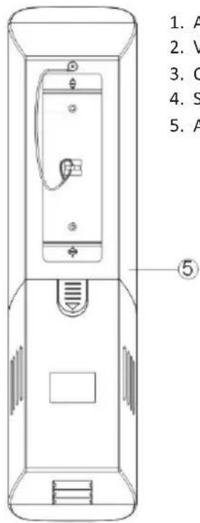
text_image
1. A 2. V 3. C 4. S 5. A ⑤natural_image
Technical line drawing of a door panel with a wall-mounted bracket and hatched material (no text or symbols)natural_image
Technical line drawing of a vertical mechanical device with internal compartments and mounting holes (no text or symbols)
natural_image
Technical line drawing of a vertical cylindrical device with internal compartments and mounting holes (no text or symbols)natural_image
Technical line drawing of a vertical cylindrical device with internal compartments and mounting holes (no text or symbols)
natural_image
Technical line drawing of a vertical device with internal components and mounting holes (no text or symbols)natural_image
Technical line drawing of two vertical electrical enclosure units with internal compartments and mounting holes (no text or symbols)B) CON MODULI TECHCONNECT
text_image
Technical diagram of a device rear panel with labeled components and numbered partsnatural_image
Architectural floor plan of a mobile phone showing internal compartments and ventilation slots (no text or labels)text_image
Technical diagram of a device rear panel with labeled components and internal layoutnatural_image
Black triangular warning symbol with a lightning bolt inside, indicating electrical hazard (no text)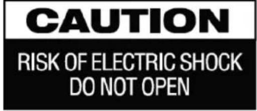
text_image
CAUTION RISK OF ELECTRIC SHOCK DO NOT OPEN
natural_image
Black triangular warning symbol with exclamation mark (no text or numbers)CAUTION: TO REDUCE THE RISK OF ELECTRIC SHOCK, DO NOT REMOVE COVER (OR BACK). NO USER-SERVICEABLE PARTS INSIDE. REFER SERVICING TO QUALIFIED SERVICE PERSONNEL.

The lightning flash with arrowhead symbol, within an equilateral triangle, is intended to alert the user to the presence of uninsulated "dangerous voltage" within the product's enclosure that may be of sufficient magnitude to constitute a risk of electric shock to persons.

The exclamation point within an equilateral triangle is intended to alert the user to the presence of important operating and maintenance (servicing) instructions in the literature accompanying the appliance.
WARNING: TO REDUCE THE RISK OF FIRE OR ELECTRIC SHOCK, DO NOT EXPOSE THIS APPLIANCE TO RAIN OR MOISTURE.
text_image
ReHS WEE/AB00475Y TUV SUD CEtext_image
Technical diagram of a vertical cylindrical device with numbered annotations pointing to internal components.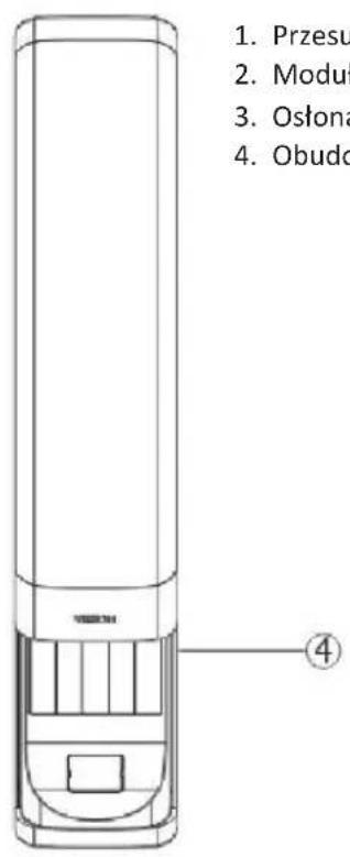
text_image
1. Przesu 2. Moduń 3. Ostona 4. Obudtext_image
Technical diagram of a device with numbered components, likely an elevator or control panel.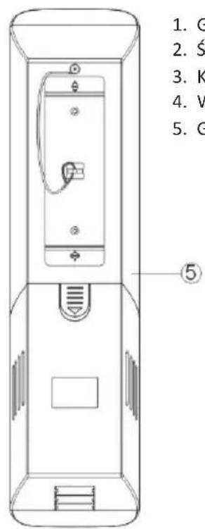
text_image
1. G 2. S 3. K 4. V 5. G ⑤natural_image
Technical line drawing of a door panel with a wall-mounted bracket and hatched material (no text or symbols)natural_image
Technical line drawing of a vertical mechanical device with internal compartments and mounting holes (no text or symbols)
natural_image
Technical line drawing of a vertical cylindrical device with internal compartments and mounting holes (no text or symbols)natural_image
Technical line drawing of a vertical cylindrical device with internal compartments and mounting holes (no text or symbols)
natural_image
Technical line drawing of a vertical cylindrical device with internal compartments and mounting holes (no text or symbols)natural_image
Technical line drawing of two vertical electrical enclosure units with internal compartments and mounting holes (no text or symbols)B) UŻYCIE MODUŁÓW TECHCONNECT
text_image
Technical diagram of a device rear panel with labeled components and numbered partsnatural_image
Architectural floor plan of a mobile phone showing internal compartments and ventilation slots (no text or labels)text_image
Technical diagram of an electronic device showing internal components and labeled parts, including a connector and terminal block.natural_image
Black triangular warning symbol with a white lightning bolt inside, indicating electrical hazard (no text)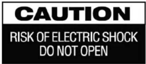
text_image
CAUTION RISK OF ELECTRIC SHOCK DO NOT OPEN
natural_image
Black triangular warning symbol with exclamation mark (no text or numbers)CAUTION: TO REDUCE THE RISK OF ELECTRIC SHOCK, DO NOT REMOVE COVER (OR BACK). NO USER-SERVICEABLE PARTS INSIDE. REFER SERVICING TO QUALIFIED SERVICE PERSONNEL.

The lightning flash with arrowhead symbol, within an equilateral triangle, is intended to alert the user to the presence of uninsulated "dangerous voltage" within the product's enclosure that may be of sufficient magnitude to constitute a risk of electric shock to persons.

The exclamation point within an equilateral triangle is intended to alert the user to the presence of important operating and maintenance (servicing) instructions in the literature accompanying the appliance.
WARNING: TO REDUCE THE RISK OF FIRE OR ELECTRIC SHOCK, DO NOT EXPOSE THIS APPLIANCE TO RAIN OR MOISTURE.
text_image
ReHS WEE/AB0047SY TUV SUD CEUSAR APENAS EM TOMADAS CA DOMÉSTICAS
text_image
Technical diagram of a vertical cylindrical device with numbered components labeled ①, ②, and ③.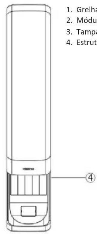
text_image
1. Grelha 2. Módu 3. Tampa 4. Estrut ④- Grelha deslizante
- Módulos TechConnect
- Tampa de saída de cabos
- Estrutura da coluna
TRASEIRA
text_image
Diagram of a device with numbered parts labeled 1 to 4, showing internal components and control buttons.
text_image
1. C 2. M de 3. C 4. S 5. C ⑤natural_image
Technical line drawing of a door panel with a wall-mounted bracket and hatched material (no text or symbols)natural_image
Technical line drawing of a vertical mechanical device with internal compartments and mounting holes (no text or symbols)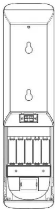
natural_image
Technical line drawing of a vertical cylindrical device with internal compartments and mounting holes (no text or symbols)2. Remover a tampa posterior dos altifalantes
natural_image
Technical line drawing of a vertical cylindrical device with internal compartments and mounting holes (no text or symbols)
natural_image
Technical line drawing of a vertical cylindrical device with internal compartments and mounting holes (no text or symbols)natural_image
Technical line drawing of two vertical electrical enclosure units with internal compartments and mounting holes (no text or symbols)text_image
Technical diagram of a device rear panel with labeled components and numbered partsnatural_image
Architectural floor plan of a mobile phone showing internal compartments and ventilation slots (no text or labels)Passo 2: Ligar a saída áudio (conector verde) no descodificador à entrada no amplificador, tal como indicado na figura.