
8200 - Multitools DREMEL - Free user manual and instructions
Find the device manual for free 8200 DREMEL in PDF.
| Product type | Cordless rotary multi-tool |
| Brand | Dremel |
| Model | 8200 |
| Rated voltage | 7.2 V |
| Battery capacity | 1.3-1.5 Ah |
| No-load speed | 5000-30000 rpm |
| Collet capacity | 0.8 mm, 1.6 mm, 2.4 mm, 3.2 mm |
| Charger | Input 230 V, 50-60 Hz, 26 W; Output 3.6-10.8 V, 1.5 A |
| Weight | Approximately 0.5 kg (with battery) |
| Dimensions | Approximately 20 x 5 x 5 cm |
| Housing material | Reinforced plastic |
| Power source | Integrated rechargeable lithium-ion battery |
| Runtime | Variable depending on use, approximately 30 minutes |
| Variable speed | Yes, by slider (5 positions: 5000-30000 rpm) |
| Spindle lock | Yes, lock button |
| Clamping system | Collet chucks (4 sizes) and EZ Twist cap with integrated wrench |
| Main functions | Grinding, sanding, metal brushing, polishing, cutting, carving, engraving |
| Compatible accessories | Dremel accessories with shank from 0.8 to 3.2 mm |
| Stall protection | Yes, automatic stop in case of jamming |
| Sound level | Pressure: 74 dB(A); Power: 85 dB(A) |
| Vibration | 2.2 m/s² (uncertainty K=1.5 m/s²) |
| Maintenance and cleaning | Clean with compressed air; do not use solvents |
| Spare parts | Collets, lock nut, battery, charger available from Dremel |
| Warranty | Compliant with applicable legal regulations |
| Repairability | Entrust to a Dremel service center |
Frequently Asked Questions - 8200 DREMEL
User questions about 8200 DREMEL
0 question about this device. Answer the ones you know or ask your own.
Ask a new question about this device
Download the instructions for your Multitools in PDF format for free! Find your manual 8200 - DREMEL and take your electronic device back in hand. On this page are published all the documents necessary for the use of your device. 8200 by DREMEL.
USER MANUAL 8200 DREMEL
natural_image
Illustration of a DREAM 8100 handheld electric shaver with visible branding and control buttons (no text beyond brand name)GB Original instructions 18
DE Übersetzung der Originalbedienungsanleitung 24
FR Traduction de la notice originale 32
IT Traduzione delle istruzioni originali 40
NL Vertaling van de originele gebruiksaanwijzing 47
DA Oversættelse af betjeningsvejledning 55
SV Översättning av originalinstruktioner 62
NO Oversettelse av originalinstruksjonene 69
FI Käännös alkuperäisistä ohjeista 75
ET Algsete juhiste tõlge 82
LT Originalių instrukcijų vertimas 89
LV Originālās lietošanas pamācības tulkojums 96
AR
ترجمة التعليمات الأصلية
1
natural_image
Line drawing of a hand holding a DREAM 100 electric drill bit, no text or symbols present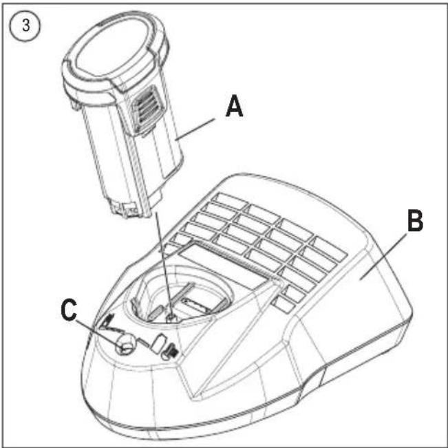
natural_image
Line drawing of a hand using a DREAMC electric drill pen (no text or symbols on the diagram itself)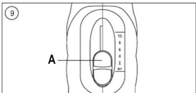
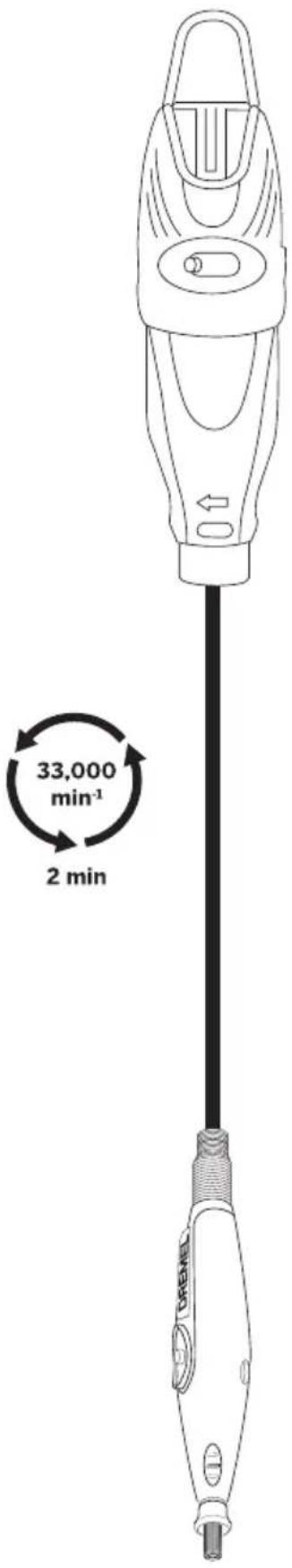
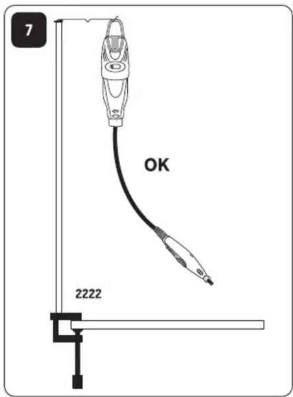
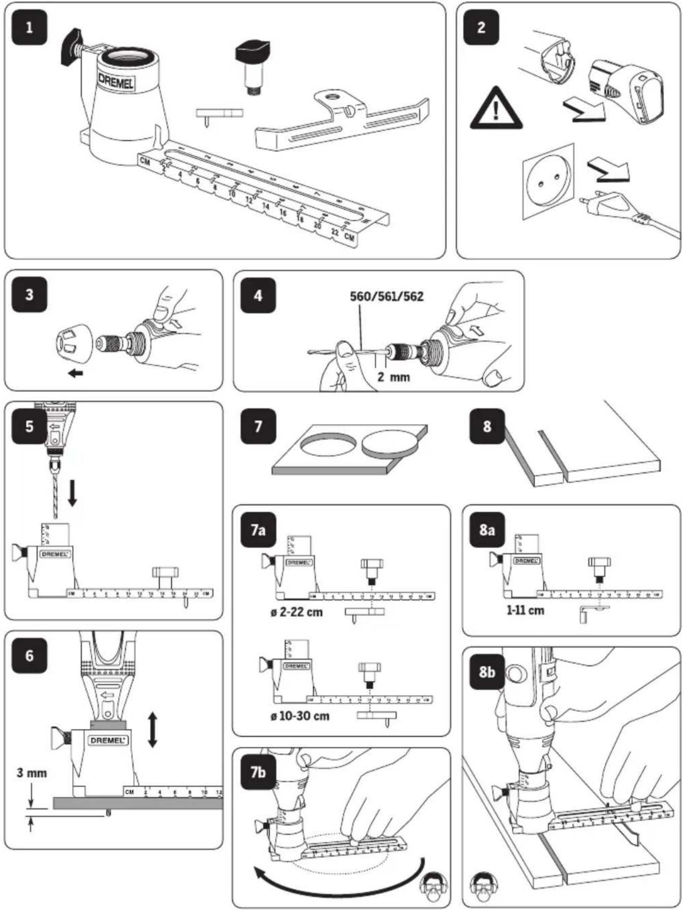
GB For optimum performance allow your new Flexshaft to run at high speed on your rotary tool in a vertical position for 2 minutes before use.
DE Um die Leistung der biegsamen Welle zu erhöhen, unbedingt vor Erstgebrauch 2 Minuten bei hoher Geschwindigkeit in vertikaler Position laufen lassen, bevor Sie damit arbeiten.
FR Pour obtenir les meilleures performances de votre nouvel arbre flexible, il est important de le roder en le faisant tourner à vide, à la vitesse maximum, pendant 2 minutes en position verticale.
IT Per ottimizzare le performance del vostro nuovo albero flessibile fatelo girare ad alta velocità sul vostro miniutensile in posizione verticale per due minuti prima di usarlo.
NL Laat uw nieuwe flexibele as voor een optimale prestatie gedurende 2 minuten voor gebruik in verticale positie op hoge snelheid op uw rotatiegereedschap lopen.
DA For optimal udnyttelse af den fleksible aksel, anbefales det at den kører ved høj hastighed uden belastning i 2 minutter inden brug.
SV Kör det roterande verktyget i hög hastighet med den nya böjliga axeln i lodrät position i två minuter innan du använder det för att få bästa prestanda.
NO For å oppnå optimal ytelse bør du før bruk kjøre den fleksible slangen på full hastighet med det roterende verktøyet i loddrett stilling i 2 minutter.
FI Parhaan mahdollisen käyttötehon varmistamiseksi anna uuden taipuisan akselin käydä suurella nopeudella korkeanopeuksiseen työkaluun kiinnitettynä pystysuorassa asennossa 2 minuutin ajan ennen käyttöä.
ET Optimaalse jõudluse tagamiseks laske oma uuel Flexshaft-seadmel enne kasutamist 2 minutit suurel kiirusel vertikaalasendis töötada.
LT Kad veiktu optimaliai, prieš pirmakart naudodami leiskite ant sukamojo irankio uždėtam „Flexshaft“ dideliu greičiu vertikaliai veikti 2 minutes.
LV Lai nodrošinātu optimālu ierīces darbību, divas minūtes pirms ierīces lietošanas darbiniet jauno, elastīgo skrūvvārpstu uz rotējošā rīka vertikālā stāvoklī.
AR
ال Tallinn en la l'الله المُمّدًا، herck موتور Flexshaft
الجديد الخAccessyk يعمل على مرعة مiertعمة على الأدامة الدوارة في
وIncreasing صودي لمدة دقيتين بعد الاستثماني
225
565/566
568
575
natural_image
Illustration of a handheld device with a knob and lever, showing a curved arrow indicating rotation (no text or symbols)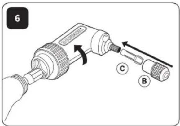
natural_image
Illustration of a hand holding a mechanical component with directional arrows indicating movement (no text or symbols)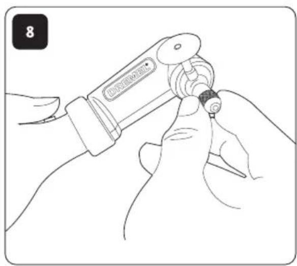
576
natural_image
Line drawing of a hairbrush tool emitting a circular component with an arrow indicating rotation (no text or symbols)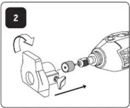
natural_image
Mechanical assembly diagram showing a tool inserted into a component with directional arrows indicating motion (no text or symbols)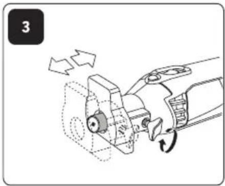
natural_image
Mechanical tool diagram showing a turning process with arrows indicating motion (no text or symbols)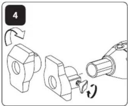
577
natural_image
Line drawing of a hairbrush tool applying material to a circular component, with an arrow indicating rotation (no text or symbols)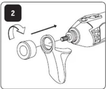
natural_image
Diagram showing a tool applying material to a mechanical component, with no visible text or symbols.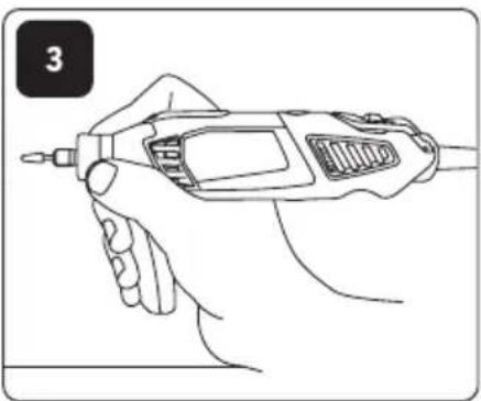
natural_image
Line drawing of a hand holding a handheld electric drill bit (no text or symbols)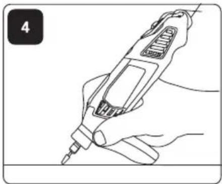
natural_image
Line drawing of a hand holding a screwdriver, no text or symbols present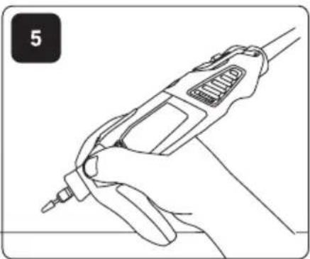
natural_image
Line drawing of a hand holding a screwdriver or drill bit (no text or symbols)675
678
| [38KW] | [46WW] |  | [HTB3] |  |  |  |  |  |  |  |  |
| 105 35.000 | ■ | ■ | ■ | ||||||||
| 106 35.000 | ■ | ■ | ■ | ||||||||
| 107 35.000 | ■ | ■ | ■ | ||||||||
| 108 35.000 | ■ | ■ | ■ | ||||||||
| 110 35.000 | ■ | ■ | ■ | ||||||||
| 111 35.000 | ■ | ■ | ■ | ||||||||
| 113 35.000 | ■ | ■ | ■ | ||||||||
| 114 30.000 | ■ | ■ | ■ | ||||||||
| 115 30.000 | ■ | ■ | ■ | ||||||||
| 117 30.000 | ■ | ■ | ■ | ||||||||
| 118 30.000 | ■ | ■ | ■ | ||||||||
| 125 30.000 | ■ | ■ | ■ | ||||||||
| 134 30.000 | ■ | ■ | ■ | ||||||||
| 144 30.000 | ■ | ■ | ■ | ||||||||
| 191 30.000 | ■ | ■ | ■ | ||||||||
| 192 30.000 | ■ | ■ | ■ | ||||||||
| 193 30.000 | ■ | ■ | ■ | ||||||||
| 194 30.000 | ■ | ■ | ■ | ||||||||
| 196 30.000 | ■ | ■ | ■ | ||||||||
| 199 30.000 | ■ | ■ | ■ | ||||||||
| 403 15.000 | ■ | ■ | ■ | ■ | |||||||
| 404 15.000 | ■ | ■ | ■ | ■ | |||||||
| 405 15.000 | ■ | ■ | ■ | ■ | |||||||
| 407 35.000 | ■ | ■ | ■ | ■ | ■ | ||||||
| 408 35.000 | ■ | ■ | ■ | ■ | ■ | ||||||
| 409 35.000 402 | ■ | ■ | ■ | ■ | |||||||
| 414 20.000 401 | ■ | ■ | ■ | ■ | |||||||
| 420 35.000 402 | ■ | ■ | ■ | ■ | |||||||
| 422 20.000 401 | ■ | ■ | ■ | ■ | |||||||
| 423S 20.000 (SC)402 | ■ | ■ | ■ | ■ | |||||||
| 425 20.000 402 | ■ | ■ | |||||||||
| 426 35.000 402 | ■ | ■ | ■ | ■ | |||||||
| 428 15.000 | ■ | ■ | ■ | ■ | |||||||
| 429 20.000 401 | ■ | ■ | ■ | ■ | |||||||
| 430 35.000 | ■ | ■ | ■ | ■ | ■ | ||||||
| 431 35.000 | ■ | ■ | ■ | ■ | ■ | ||||||
| 432 35.000 | ■ | ■ | ■ | ■ | ■ | ||||||
| 438 35.000 | ■ | ■ | ■ | ■ | ■ | ||||||
| 442 15.000 | ■ | ■ | ■ | ■ | |||||||
| 443 15.000 | ■ | ■ | ■ | ■ | |||||||
| 453 30.000 1453 | ■ | ■ | ■ | ||||||||
| 454 30.000 1453 | ■ | ■ | ■ | ||||||||
| 455 30.000 1453 | ■ | ■ | ■ | ||||||||
| 457 30.000 1453 | ■ | ■ | ■ | ||||||||
| 462 30.000 | ■ | ■ | ■ | ||||||||
| 502 35.000 | ■ | ■ | ■ | ■ | ■ | ||||||
| 504 35.000 | ■ | ■ | ■ | ■ | ■ | ||||||
| 511S 20.000 (SC)402 | ■ | ■ | |||||||||
| 512S 20.000 (SC)402 | ■ | ■ | |||||||||
| 516 20.000 | ■ | ■ | ■ | ■ | |||||||
| 520 20.000 | ■ | ■ | ■ | ■ | |||||||
| 530 15.000 | ■ | ■ | ■ | ■ | |||||||
| 531 15.000 | ■ | ■ | ■ | ■ |

natural_image
Collection of grayscale icons representing various objects and materials (no text or symbols)| [SDOT] | [HSK] |  | [DRGK] |  |  |  |  |  |  |  |  |
| 532 15.000 | ■ | ■ | ■ | ■ | |||||||
| 535 15.000 | ■ | ■ | |||||||||
| 536 15.000 | ■ | ■ | |||||||||
| 537 15.000 | ■ | ■ | |||||||||
| 538 20.000 | ■ | ||||||||||
| 540 35.000 402 | ■ | ■ | ■ | ■ | ■ | ■ | |||||
| 542 35.000 | ■ | ■ | |||||||||
| 546 35.000 670 | ■ | ■ | |||||||||
| 561 35.000 565 | ■ | ■ | ■ | ||||||||
| 562 35.000 566 | |||||||||||
| 569 20.000 568 | |||||||||||
| 570 20.000 568 | |||||||||||
| 612 35.000 231/335 | ■ | ■ | |||||||||
| 615 35.000 231/335 | ■ | ■ | |||||||||
| 640 35.000 231/335 | ■ | ■ | |||||||||
| 650 35.000 231/335 | ■ | ■ | |||||||||
| 652 35.000 231/335 | ■ | ■ | |||||||||
| 654 35.000 231/335 | ■ | ■ | |||||||||
| 655 35.000 231/335 | ■ | ■ | |||||||||
| 932 25.000 | ■ | ■ | ■ | ■ | |||||||
| 952 25.000 | ■ | ■ | ■ | ■ | |||||||
| 953 25.000 | ■ | ■ | ■ | ■ | |||||||
| 997 25.000 | ■ | ■ | ■ | ■ | |||||||
| 4485 35.000 | |||||||||||
| 4486 35.000 | |||||||||||
| 7103 25.000 | ■ | ■ | ■ | ■ | |||||||
| 7105 25.000 | ■ | ■ | ■ | ■ | |||||||
| 7122 25.000 | ■ | ■ | ■ | ■ | |||||||
| 7134 25.000 | ■ | ■ | ■ | ■ | |||||||
| 7144 25.000 | ■ | ■ | ■ | ■ | |||||||
| 8153 25.000 | ■ | ■ | ■ | ■ | ■ | ||||||
| 8193 20.000 | ■ | ■ | ■ | ■ | ■ | ||||||
| 8215 20.000 | ■ | ■ | ■ | ■ | ■ | ||||||
| 9901 30.000 | ■ | ■ | ■ | ■ | |||||||
| 9903 30.000 | ■ | ■ | ■ | ■ | |||||||
| 9905 30.000 | ■ | ■ | ■ | ■ | |||||||
| 9910 30.000 | ■ | ■ | ■ | ■ | |||||||
| 9911 30.000 | ■ | ■ | ■ | ■ | |||||||
| 9931 35.000 | ■ | ■ | ■ | ■ | |||||||
| 9934 35.000 | ■ | ■ | ■ | ■ | |||||||
| 9936 35.000 | ■ | ■ | ■ | ■ | |||||||
| 83322 25.000 | |||||||||||
| 84922 25.000 | |||||||||||
| 85422 20.000 | |||||||||||
| 85602 20.000 | |||||||||||
| SC406 | 35.000 | SC402 | ■ | ■ | ■ | ■ | ■ | ■ | |||
| SC409 | 35.000 | SC402 | ■ | ■ | ■ | ■ | ■ | ■ | |||
| SC456 | 35.000 | SC402 | ■ | ■ | ■ | ■ | ■ | ■ | |||
| SC476 | 35.000 | SC402 | |||||||||
| SC544 | 35.000 | SC402 | ■ | ■ | ■ | ||||||
| SC545 | 35.000 | SC402 |

natural_image
Collection of grayscale icons representing various objects and materials (e.g., bricks, glass, paper, etc.) without any text or symbols.
natural_image
Two parallel horizontal lines with four black square markers at top (no text or symbols)


GB
CE DECLARATION OF CONFORMITY We declare under our sole responsibility that this product is in conformity with the following standards or standardized documents: EN60745, EN55014, in accordance with the provisions of the directives 2006/95/EC, 2004/108/EC, 2006/42/EC.
NOISE/VIBRATION Measured in accordance with EN60745 the sound pressure level of this tool is 74 dB(A) and the sound power level 85 dB(A) (standard deviation: 3 dB), and the vibration 2.2 m/s² (hand-arm method, uncertainty K=1.5 m/s²).
NOTE: The declared vibration total value has been measured in accordance with a standard test method and may be used for comparing one tool with another. It may also be used in a preliminary assessment of exposure.
WARNING
The vibration emission during actual use of the power tool can differ from the declared total value depending on the ways in which you use the tool. Make an estimation of the
exposure in the actual conditions of use and identify the safety measures for personal protection accordingly (taking account of all parts of the operating cycle such as the times when the tool is switched off and when it is running idle in addition to the trigger time).
Technical file at: SKIL Europe BV (PT-SEU/PJE), 4825 BD Breda, NL.
DE
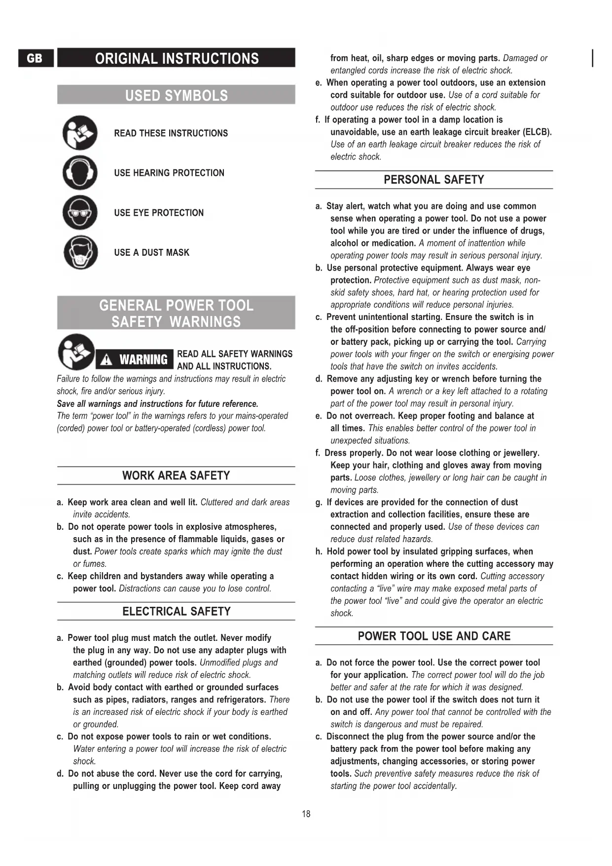
READ THESE INSTRUCTIONS

USE HEARING PROTECTION

USE EYE PROTECTION

USE A DUST MASK
GENERAL POWER TOOL SAFETY WARNINGS

WARNING
READ ALL SAFETY WARNINGS AND ALL INSTRUCTIONS.
Failure to follow the warnings and instructions may result in electric shock, fire and/or serious injury.
Save all warnings and instructions for future reference.
The term "power tool" in the warnings refers to your mains-operated (corded) power tool or battery-operated (cordless) power tool.
WORK AREA SAFETY
a. Keep work area clean and well lit. Cluttered and dark areas invite accidents.
b. Do not operate power tools in explosive atmospheres, such as in the presence of flammable liquids, gases or dust. Power tools create sparks which may ignite the dust or fumes.
c. Keep children and bystanders away while operating a power tool. Distractions can cause you to lose control.
ELECTRICAL SAFETY
a. Power tool plug must match the outlet. Never modify the plug in any way. Do not use any adapter plugs with earthed (grounded) power tools. Unmodified plugs and matching outlets will reduce risk of electric shock.
b. Avoid body contact with earthed or grounded surfaces such as pipes, radiators, ranges and refrigerators. There is an increased risk of electric shock if your body is earthed or grounded.
c. Do not expose power tools to rain or wet conditions.
Water entering a power tool will increase the risk of electric shock.
d. Do not abuse the cord. Never use the cord for carrying, pulling or unplugging the power tool. Keep cord away
from heat, oil, sharp edges or moving parts. Damaged or entangled cords increase the risk of electric shock.
e. When operating a power tool outdoors, use an extension cord suitable for outdoor use. Use of a cord suitable for outdoor use reduces the risk of electric shock.
f. If operating a power tool in a damp location is unavoidable, use an earth leakage circuit breaker (ELCB). Use of an earth leakage circuit breaker reduces the risk of electric shock.
PERSONAL SAFETY
a. Stay alert, watch what you are doing and use common sense when operating a power tool. Do not use a power tool while you are tired or under the influence of drugs, alcohol or medication. A moment of inattention while operating power tools may result in serious personal injury.
b. Use personal protective equipment. Always wear eye protection. Protective equipment such as dust mask, non-skid safety shoes, hard hat, or hearing protection used for appropriate conditions will reduce personal injuries.
c. Prevent unintentional starting. Ensure the switch is in the off-position before connecting to power source and/or battery pack, picking up or carrying the tool. Carrying power tools with your finger on the switch or energising power tools that have the switch on invites accidents.
d. Remove any adjusting key or wrench before turning the power tool on. A wrench or a key left attached to a rotating part of the power tool may result in personal injury.
e. Do not overreach. Keep proper footing and balance at all times. This enables better control of the power tool in unexpected situations.
f. Dress properly. Do not wear loose clothing or jewellery. Keep your hair, clothing and gloves away from moving parts. Loose clothes, jewellery or long hair can be caught in moving parts.
g. If devices are provided for the connection of dust extraction and collection facilities, ensure these are connected and properly used. Use of these devices can reduce dust related hazards.
h. Hold power tool by insulated gripping surfaces, when performing an operation where the cutting accessory may contact hidden wiring or its own cord. Cutting accessory contacting a "live" wire may make exposed metal parts of the power tool "live" and could give the operator an electric shock.
POWER TOOL USE AND CARE
a. Do not force the power tool. Use the correct power tool for your application. The correct power tool will do the job better and safer at the rate for which it was designed.
b. Do not use the power tool if the switch does not turn it on and off. Any power tool that cannot be controlled with the switch is dangerous and must be repaired.
c. Disconnect the plug from the power source and/or the battery pack from the power tool before making any adjustments, changing accessories, or storing power tools. Such preventive safety measures reduce the risk of starting the power tool accidentally.
d. Store idle power tools out of the reach of children and do not allow persons unfamiliar with the power tool or these instructions to operate the power tool. Power tools are dangerous in the hands of untrained users.
e. Maintain power tools. Check for misalignment or binding of moving parts, breakage of parts and any other condition that may affect the power tools operation. If damaged, have the power tool repaired before use. Many accidents are caused by poorly maintained power tools.
f. Keep cutting tools sharp and clean. Properly maintained cutting tools with sharp cutting edges are less likely to bind and are easier to control.
g. Use the power tool, accessories and tool bits etc., in accordance with these instructions, taking into account the working conditions and the work to be performed. Use of the power tool for operations different from those intended could result in a hazardous situation.
BATTERY TOOL USE AND CARE
a. Recharge only with the charger specified by the manufacturer. A charger that is suitable for one type of battery pack may create a risk of fire when used with another battery pack.
b. Use power tools only with specifically designated battery packs. Use of any other battery packs may create a risk of injury and fire.
c. When battery pack is not in use, keep it away from other metal objects like paper clips, coins, keys, nails, screws, or other small metal objects that can make a connection from one terminal to another. Shorting the battery terminals together may cause burns or a fire.
d. Under abusive conditions, liquid may be ejected from the battery; avoid contact. If contact accidentally occurs, flush with water. If liquid contacts eyes, additionally seek medical help. Liquid ejected from the battery may cause irritation or burns.
SERVICE
a. Have your power tool serviced by a qualified repair person using only identical replacement parts. This will ensure that the safety of the power tool is maintained.
SAFETY INSTRUCTIONS FOR ALL OPERATIONS
SAFETY WARNINGS COMMON FOR GRINDING, SANDING, WIRE BRUSHING, POLISHING OR ABRASIVE CUTTING-OFF OPERATIONS
a. This power tool is intended to function as a grinder, sander, wire brush, polisher or cut-off tool. Read all safety warnings, instructions, illustrations and specifications provided with this power tool. Failure to follow all instructions listed below may result in electric shock, fire and/or serious injury.
b. Do not use accessories which are not specifically designed and recommended by the tool manufacturer.
Just because the accessory can be attached to your power tool, it does not assure safe operation.
c. The rated speed of the accessory must be at least equal to the maximum speed marked on the power tool. Accessories running faster than their rated speed can break and fly apart.
d. The outside diameter and the thickness of your accessory must be within the capacity rating of your power tool. Incorrectly sized accessories cannot be adequately guarded or controlled.
e. The arbour size of wheels, flanges, backing pads or any other accessory must properly fit the spindle of the power tool. Accessories with arbour holes that do not match the mounting hardware of the power tool will run out of balance, vibrate excessively and may cause loss of control.
f. Do not use a damaged accessory. Before each use inspect the accessory such as abrasive wheels for chips and cracks, backing pad for cracks, tear or excess wear, wire brush for loose or cracked wires. If power tool or accessory is dropped, inspect for damage or install an undamaged accessory. After inspecting and installing anaccessory, position yourself and bystanders away from the plane of the rotating accessory and run the power tool at maximum no-load speed for one minute. Damaged accessories will normally break apart during this test time.
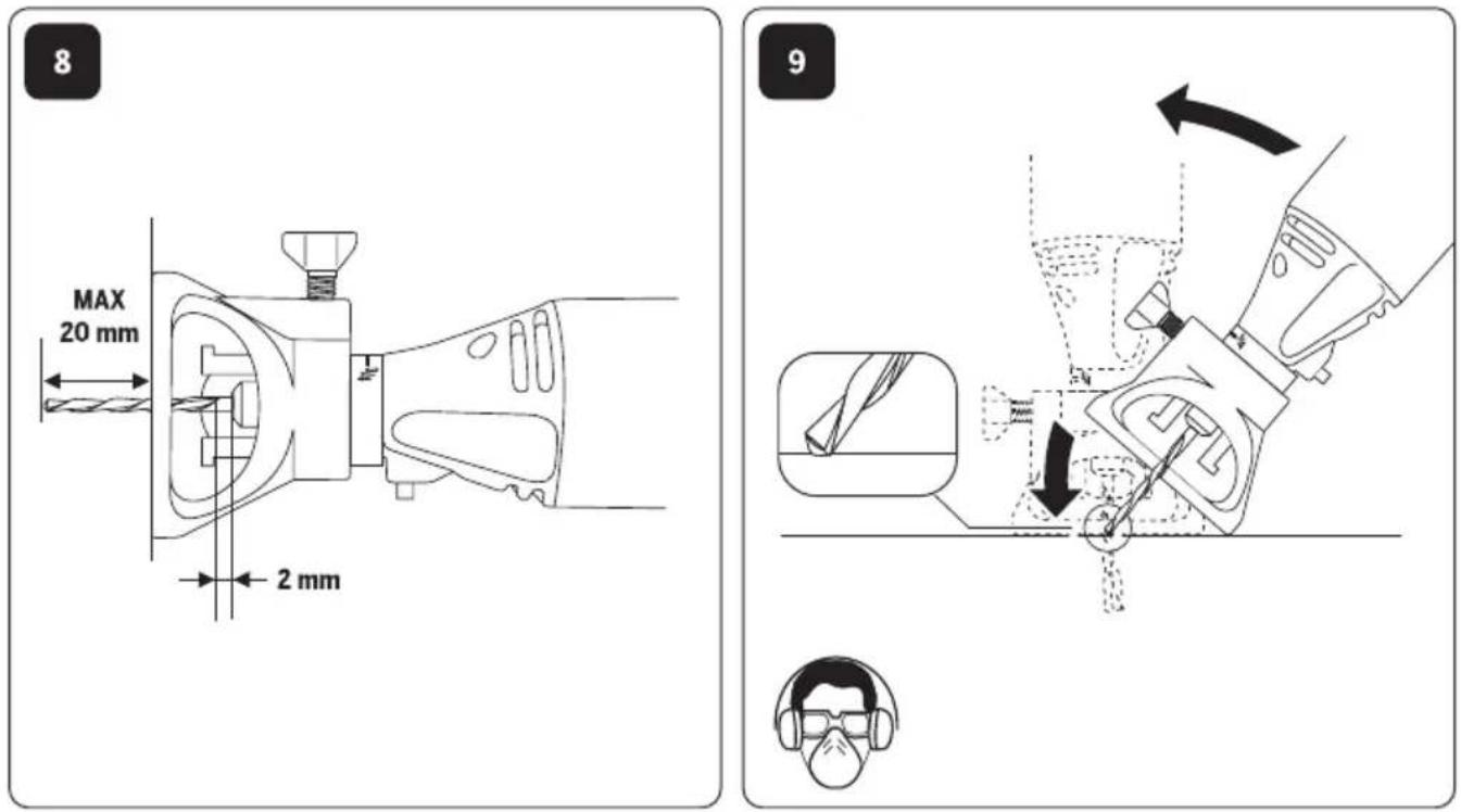
g. Wear personal protective equipment. Depending on application, use face shield, safety goggles or safety glasses. As appropriate, wear dust mask, hearing protectors, gloves and workshop apron capable of stopping small abrasive or workpiece fragments. The eye protection must be capable of stopping flying debris generated by various operations. The dust mask or respirator must be capable of filtrating particles generated by your operation. Prolonged exposure to high intensity noise may cause hearing loss.
h. Keep bystanders a safe distance away from work area. Anyone entering the work area must wear personal protective equipment. Fragments of workpiece or of a broken accessory may fly away and cause injury beyond immediate area of operation.
i. Hold power tool by insulated gripping surfaces only, when performing an operation where the cutting accessory may contact hidden wiring or its own cord. Cutting accessory contacting a "live" wire may make exposed metal parts of the power tool "live" and shock the operator.
j. Position the cord clear of the spinning accessory. If you lose control, the cord may be cut or snagged and your hand or arm may be pulled into the spinning accessory.
k. Never lay the power tool down until the accessory has come to a complete stop. The spinning accessory may grab the surface and pull the power tool out of your control.
I. Do not run the power tool while carrying it at your side. Accidental contact with the spinning accessory could snag your clothing, pulling the accessory into your body.
m. Regularly clean the power tool's air vents. The motor's fan will draw the dust inside the housing and excessive accumulation of powdered metal may cause electrical hazards.
n. Do not operate the power tool near flammable materials.
Sparks could ignite these materials.
o. Do not use accessories that require liquid coolants. Using water or other liquid coolants may result in electrocution or shock.
KICKBACK AND RELATED WARNINGS
Kickback is a sudden reaction to a pinched or snagged rotating wheel, backing pad, brush or any other accessory. Pinching or snagging causes rapid stalling of the rotating accessory which in turn causes the uncontrolled power tool to be forced in the direction opposite of the accessory's rotation at the point of the binding. For example, if an abrasive wheel is snagged or pinched by the workpiece, the edge of the wheel that is entering into the pinch point can dig into the surface of the material causing the wheel to climb out or kick out. The wheel may either jump toward or away from the operator, depending on direction of the wheel's movement at the point of pinching. Abrasive wheels may also break under these conditions. Kickback is the result of power tool misuse and/or incorrect operating procedures or conditions and can be avoided by taking proper precautions as given below.
a. Maintain a firm grip on the power tool and position your body and arm to allow you to resist kickback forces. Always use auxiliary handle, if provided, for maximum control over kickback or torque reaction during start-up. The operator can control torque reactions or kickback forces, if proper precautions are taken.
b. Never place your hand near the rotating accessory.
Accessory may kickback over your hand.
c. Do not position your body in the area where power tool will move if kickback occurs. Kickback will propel the tool in direction opposite to the wheel's movement at the point of snagging.
d. Use special care when working corners, sharp edges etc. Avoid bouncing and snagging the accessory. Corners, sharp edges or bouncing have a tendency to snag the rotating accessory and cause loss of control or kickback.
e. Do not attach a saw chain woodcarving blade or toothed saw blade. Such blades create frequent kickback and loss of control.
SAFETY WARNINGS SPECIFIC FOR GRINDING AND ABRASIVE CUTTING-OFF OPERATIONS
a. Use only wheel types that are recommended for your power tool and the specific guard designed for the selected wheel. Wheels for which the power tool was not designed cannot be adequately guarded and are unsafe.
b. Wheels must be used only for recommended applications. For example: do not grind with the side of cut-off wheel. Abrasive cut-off wheels are intended for peripheral grinding, side forces applied to these wheels may cause them to shatter.
c. Always use undamaged wheel flanges that are of correct size and shape for your selected wheel. Proper wheel flanges support the wheel thus reducing the possibility of wheel breakage. Flanges for cut-off wheels may be different from grinding wheel flanges.
d. Do not use worn down wheels from larger power tools.
Wheel intended for larger power tool is not suitable for the higher speed of a smaller tool and may burst.
ADDITIONAL SAFETY WARNINGS SPECIFIC FOR ABRASIVE CUTTING OFF OPERATIONS
a. Do not "jam" the cut-off wheel or apply excessive pressure. Do not attempt to make an excessive depth of cut. Overstressing the wheel increases the loading and susceptibility to twisting or binding of the wheel in the cut and the possibility of kickback or wheel breakage.
b. Do not position your body in line with and behind the rotating wheel. When the wheel, at the point of operation, is moving away from your body, the possible kickback may propel the spinning wheel and the power tool directly at you.
c. When wheel is binding or when interrupting a cut for any reason, switch off the power tool and hold the power tool motionless until the wheel comes to a complete stop. Never attempt to remove the cut-off wheel from the cut while the wheel is in motion otherwise kickback may occur. Investigate and take corrective action to eliminate the cause of wheel binding.
d. Do not restart the cutting operation in the workpiece. Let the wheel reach full speed and carefully reenter the cut. The wheel may bind, walk up or kickback if the power tool is restarted in the workpiece.
e. Support panels or any oversized workpiece to minimize the risk of wheel pinching and kickback. Large workpieces tend to sag under their own weight. Supports must be placed under the workpiece near the line of cut and near the edge of the workpiece on both sides of the wheel.
f. Use extra caution when making a "pocket cut" into existing walls or other blind areas. The protruding wheel may cut gas or water pipes, electrical wiring or objects that can cause kickback.
SAFETY WARNINGS SPECIFIC FOR SANDING OPERATIONS
a. Do not use excessively oversized sanding disc paper. Follow manufacturers recommendations, when selecting sanding paper. Larger sanding paper extending beyond the sanding pad presents a laceration hazard and may cause snagging, tearing of the disc or kickback.
SAFETY WARNINGS SPECIFIC FOR POLISHING OPERATIONS
a. Do not allow any loose portion of the polishing bonnet or its attachment strings to spin freely. Tuck away or trim any loose attachment strings. Loose and spinning attachment strings can entangle your fingers or snag on the workpiece.
SAFETY WARNINGS SPECIFIC FOR WIRE BRUSHING OPERATIONS
a. Be aware that wire bristles are thrown by the brush even during ordinary operation. Do not overstress the wires by applying excessive load to the brush. The wire bristles can easily penetrate light clothing and/or skin.
b. If the use of a guard is recommended for wire brushing, do not allow any interference of the wire wheel or brush
with the guard. Wire wheel or brush may expand in diameter due to work load and centrifugal forces.
c. Do not exceed 15000 min-1 when using wire brushes.

WARNING
DO NOT WORK WITH MATERIALS CONTAINING ASBESTOS (ASBESTOS IS
The machine, accessories and packaging should be sorted for environmental-friendly recycling.
ONLY FOR EUROPEAN COUNTRIES

Do not dispose of power tools into household waste! According to the European Guideline 2002/96/EC for Waste Electrical and Electronic Equipment and its implementation into national right, power tools that are no longer usable must be collected separately and disposed of in an environmentally correct manner.
SPECIFICATIONS
GENERAL SPECIFICATIONS
Voltage Rating 7,2 V
Amperage Rating....1,3–1,5 Ah
No Load Speed.... n. 5000–30000 min ^-1
Collet Capacity 0,8 mm, 1,6 mm, 2,4 mm, 3,2 mm
SPECIFICATIONS CHARGER
Input. 230 V, 50 – 60 Hz, 26 W
Use completely unrolled and safe extension cords with a capacity of 5 Amps.
ASSEMBLY
ALWAYS TURN OFF THE TOOL BEFORE CHANGING ACCESSORIES, CHANGING COLLETS, OR SERVICING THE TOOL.
IMPORTANT CHARGING NOTES
-
The charger was designed to fast charge the battery only when the battery temperature is between 32^ F ( 0^ C) and 113^ F ( 45^ C). If the battery pack is too hot or too cold, the charger will not fast charge the battery. (This may happen if the battery pack is hot from heavy use). When the battery temperature returns to between 32^ F ( 0^ C) and 113^ F ( 45^ C), the charger will automatically begin charging.
-
A substantial drop in operating time per charge may mean that the battery pack is nearing the end of its life and should be replaced.
-
Remember to unplug charger during storage period. NOTE: Use of chargers or battery packs not sold by Dremel will void the warranty.
CHARGING BATTERY PACK (MODEL 808)
Plug charger cord into your standard power outlet.
With no battery pack inserted, the charger's green indicator light will go ON. This indicates the charger is receiving power and the charger is ready for operation.
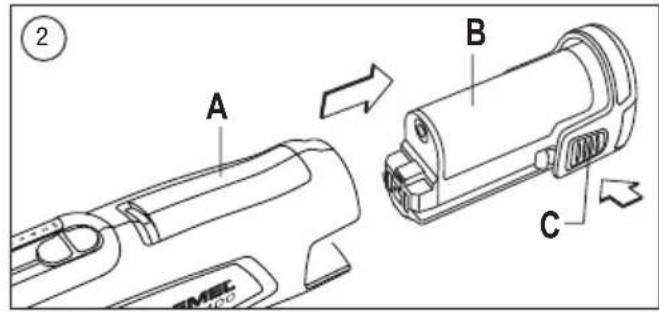
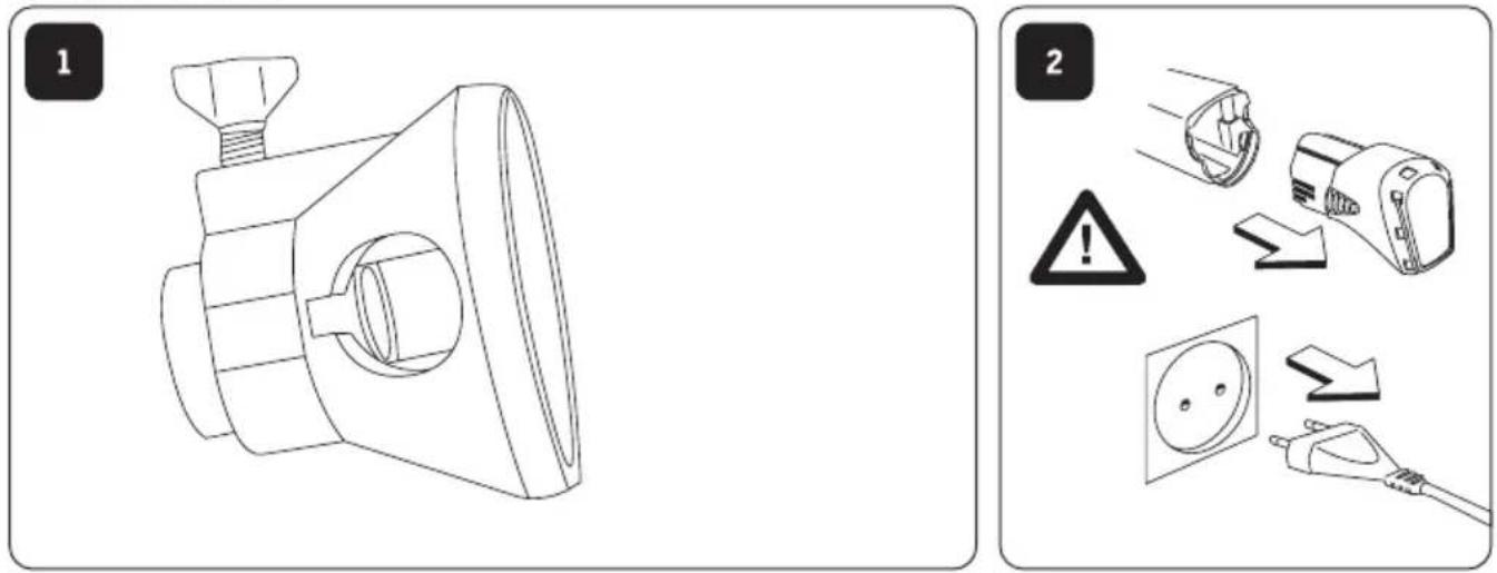
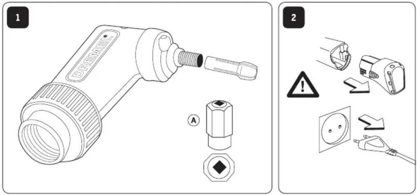
PICTURE 2
A. Tool
B. Battery pack
C. Battery release tabs
To remove the battery pack from the tool press both battery release tabs and pull the battery from the tool.
When you insert the battery pack into the charger, the charger's green indicator light will begin to "BLINK". This indicates that the battery is receiving a fast charge.
PICTURE 3
A. Battery pack
B. Charger
C. Green light
When the indicator light stops "BLINKING" (and becomes a steady green light) fast charging is complete. The battery pack is fully charged and can be removed from the charger.
When you begin the charging process of the battery pack, a steady green light could also mean the battery pack is too hot or too cold.
Fast charging is only possible when the temperature range of the battery pack is between 0°C and 45°C.
When needed, the internal fan of the charger will turn on to aid the charging process and speed.
As soon as the battery pack reaches the correct temperature range, the battery charger will automatically switch to fast charging.
The battery pack may be used even though the light may still be blinking. The light may require more time to stop blinking depending on temperature.
The purpose of the green light is to indicate that the battery pack is fast-charging. It does not indicate the exact point of full charge. The light will stop blinking in less time if the battery pack was not completely discharged.
If the green indicator light is "ON", the battery pack cannot accept a charge.
GENERAL
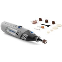
The Dremel multitool is a high quality precision tool that can be used to perform detailed and intricate tasks. The wide range of Dremel accessories and attachments allow you to perform a large variety of tasks. These include tasks such as sanding, carving, engraving, routing, cleaning and polishing.
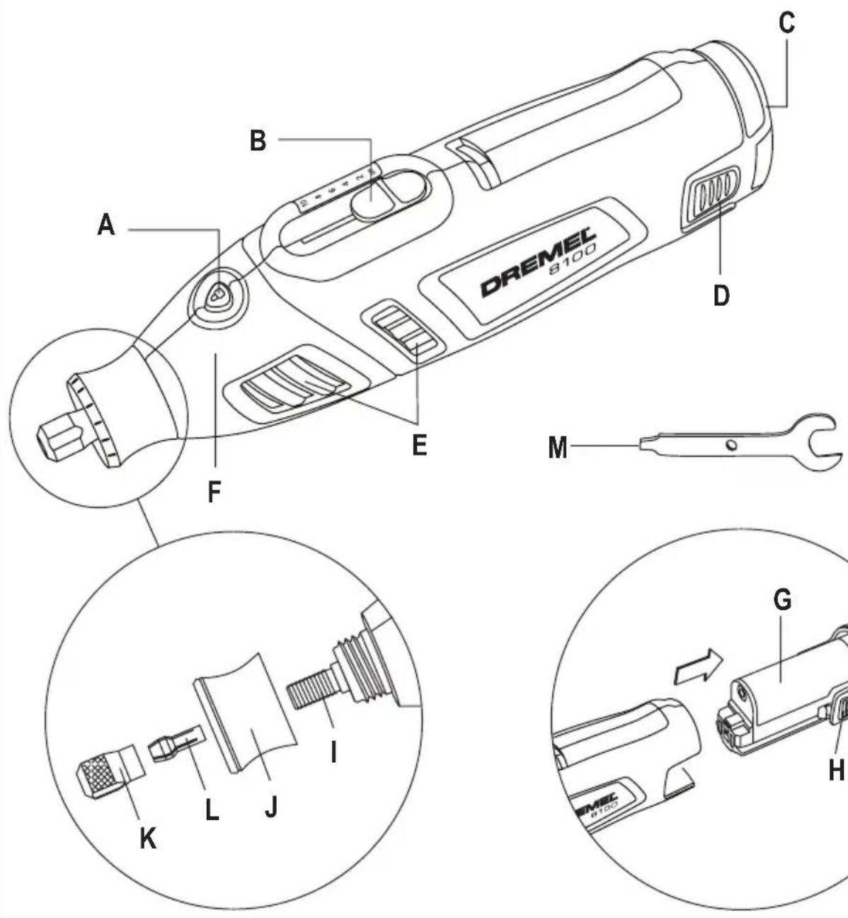
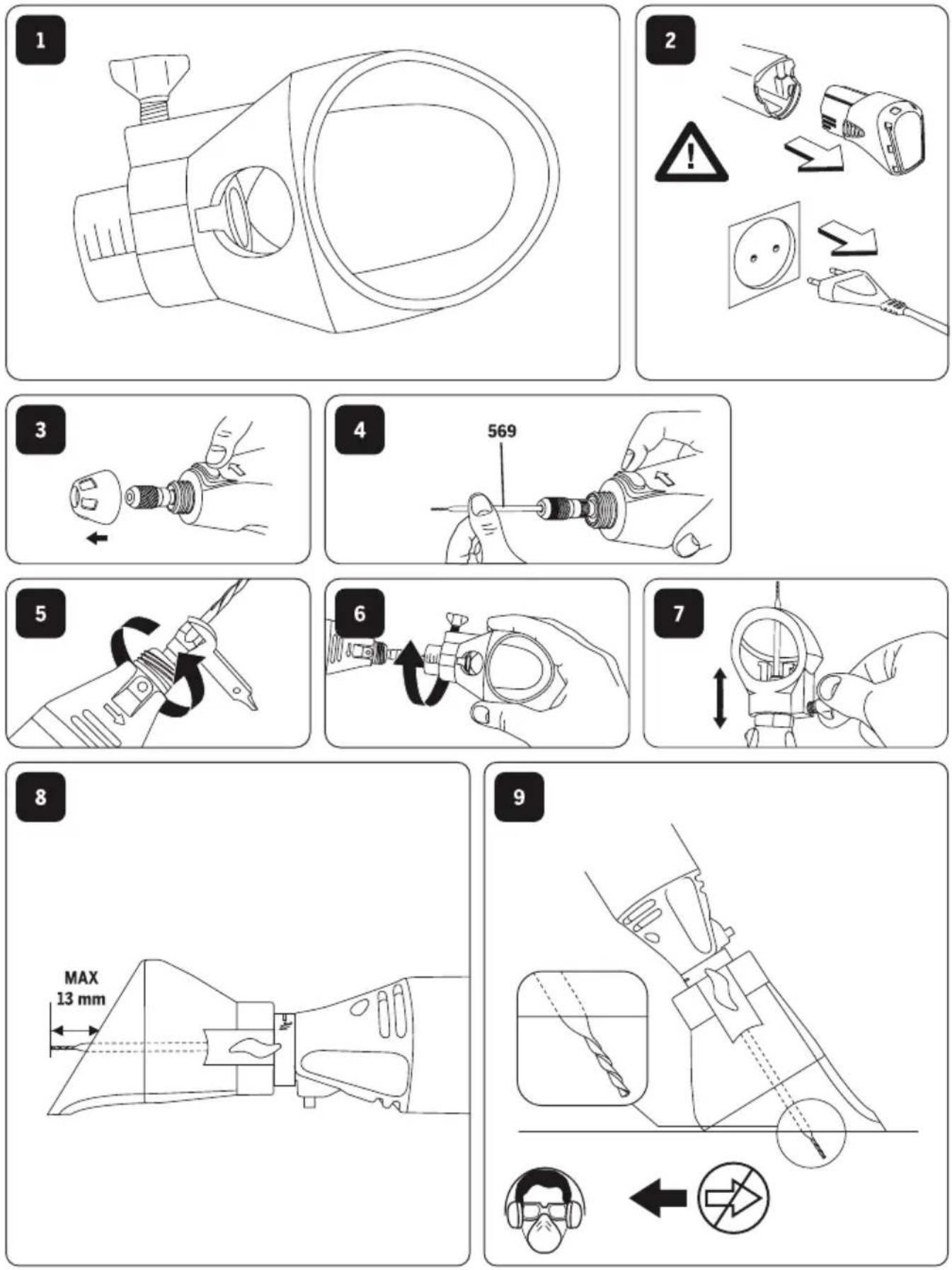
PICTURE 1
A. Shaft lock button
B. On/Off and variable speed slide switch
C. Battery pack
D. Battery release tabs
E. Ventilation openings
F. Housing
G. Battery pack
H. Battery release tabs
I. Shaft
J. EZ Twist™ integrated wrench/nose cap
K. Collet nut
L. Collet
M. Wrench
COLLETS
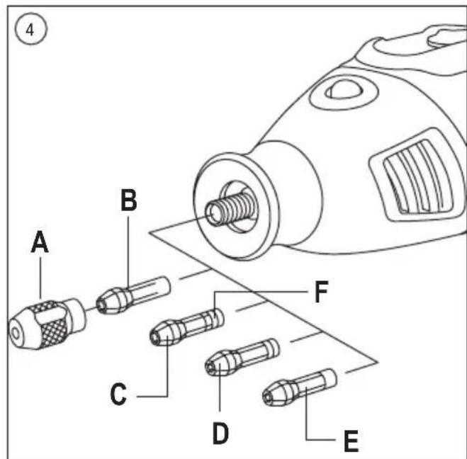
The Dremel accessories available for the multitool come with various shank sizes. Four size collets are available to accommodate the different shank sizes. Collet sizes are identified by the rings on the back of the collet.
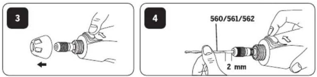
PICTURE 4
A. Collet nut
B. 3.2 mm Collet without ring (480)
C. 2.4 mm Collet with three rings (481)
D. 1.6 mm Collet with two rings (482)
E. 0.8 mm Collet with one ring (483)
F. Indentification rings
NOTE: Some multitool kits may not include all four collet sizes. Collets are available separately.
Always use the collet that matches the shank size of the accessory you plan to use. Do not force a larger diameter shank into a smaller collet.
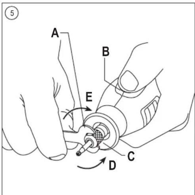
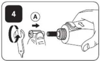
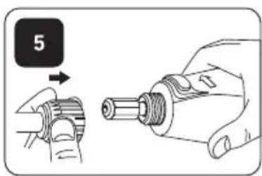
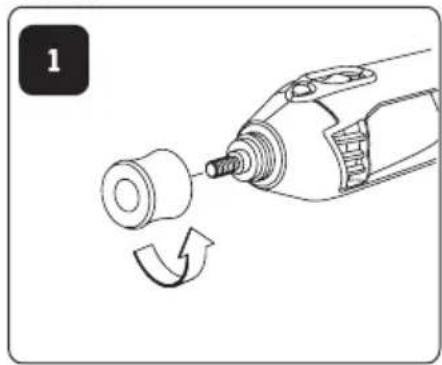
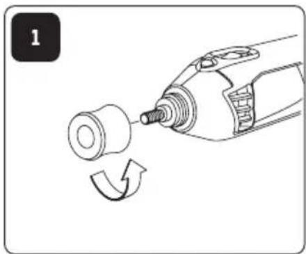
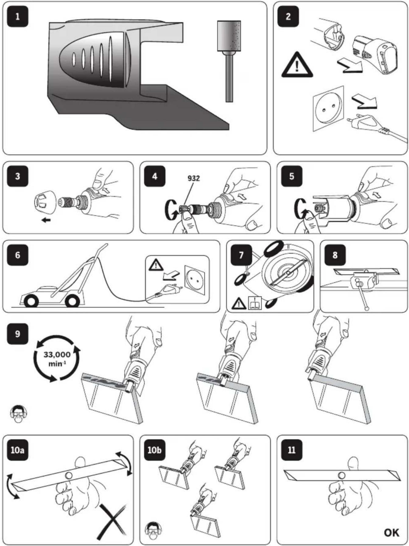
CHANGING COLLETS
PICTURE 5
A. Wrench
B. Shaft lock button
C. Collet nut
D. To loosen
E. To tighten
-
Press the shaft lock button, hold down and rotate the shaft by hand until it engages the shaft lock. Do not engage the shaft lock button while multitool is running.
-
With the shaft lock button engaged, loosen and remove the collet nut. Use the collet wrench if necessary.
- Remove the collet by pulling it free from the shaft.
- Install the appropriate size collet fully into the shaft and reinstall the collet nut finger tight. Do not fully tighten the nut when there is no bit or accessory installed.
CHANGING ACCESSORIES
- Press the shaft lock button and rotate the shaft by hand until it engages the shaft lock. Do not engage the shaft lock button while multitool is running.
- With the shaft lock button engaged, loosen (do not remove) the collet nut. Use the collet wrench if necessary.
- Insert the bit or accessory shank fully into the collet.
- With the shaft lock button engaged, finger tighten the collet nut until the bit or accessory shank is gripped by the collet.
NOTE: Be sure to read the instructions supplied with your Dremel accessory for further information on its use.
Use only Dremel tested, high performance accessories.
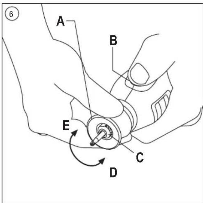
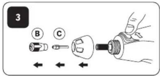
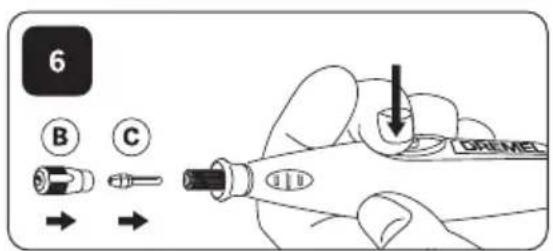
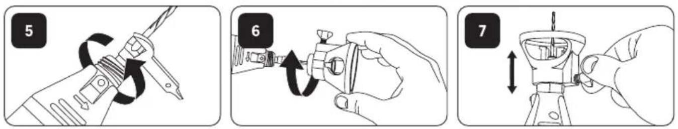
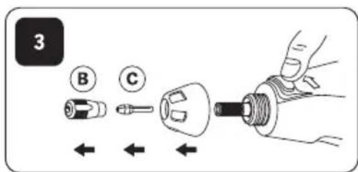
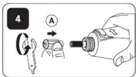
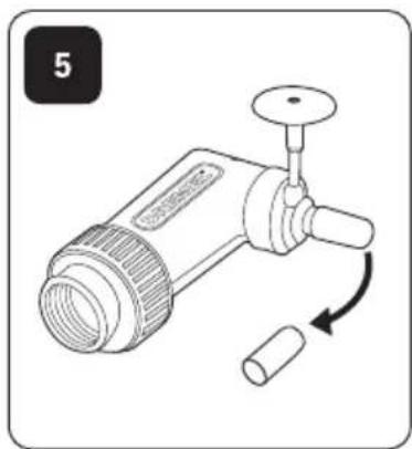
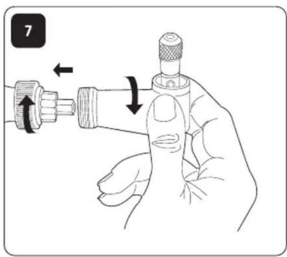
EZ TWIST™ INTEGRATED WRENCH/NOSE CAP
PICTURE 6
A. EZ Twist™ integrated wrench/nose cap
B. Shaft lock button
C. Collet nut
D. To loosen
E. To tighten
The nose cap of your tool has an integrated wrench allowing you to loosen and tighten the collet nut without the use of the standard collet wrench.
- Unscrew the nose cap from the tool, line-up the steel insert on inside of the cap with the collet nut.
- With the shaft lock engaged twist nose cap counter clockwise to loosen the collet nut. Do not engage the shaft lock button while multitool is running.
- Insert the bit or accessory shank fully into the collet.
- With the shaft lock engaged twist nose cap clockwise to tighten the collet nut.
- Screw the nose cap back into its original position. NOTE: Be sure to read the instructions supplied with your Dremel accessory for further information on its use.
Use only Dremel tested, high performance accessories.
BALANCING ACCESSORIES
For precision work, it is important that all accessories be in good balance (much the same as the tires on your automobile). To true up or balance an accessory, slightly loosen collet nut and give the accessory or collet a 1/4 turn. Re tighten collet nut and run the Rotary Tool. You should be able to tell by the sound and feel if your accessory is running in balance. Continue adjusting in this fashion until best balance is achieved.
GETTING STARTED
The first step in using the multitool is to get the "feel" of it. Hold it in your hand and feel its weight and balance. Feel the taper of the housing. This taper permits the tool to be grasped much like a pen or pencil.
Always hold the tool away from your face. Accessories can be damaged during handling and can fly apart as they come up to speed.
When holding tool, do not cover the ventilation openings with your hand. Blocking the ventilation openings could cause the motor to overheat.
IMPORTANT! Practice on scrap material first to see how the tool's high-speed action performs. Keep in mind that your multitool will perform best by allowing the speed, along with the correct Dremel accessory and attachment, to do the work for you. Do not put pressure on the tool during use, if possible. Instead, lower the spinning accessory lightly to the work surface and allow it to touch the point at which you want to begin. Concentrate on guiding the tool over the work using very little pressure from your hand. Allow the accessory to do the work.
Usually it is better to make a series of passes with the tool rather than to do the entire job with one pass. A gentle touch gives the best control and reduces the chance of error.
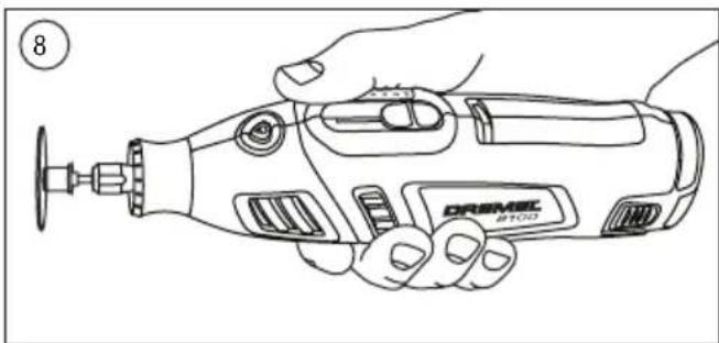
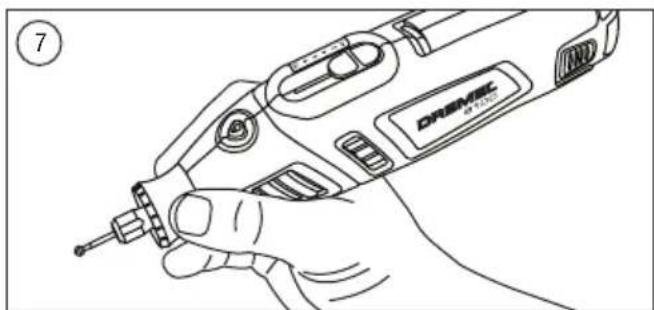
HOLDING THE TOOL
For best control in close work, grip the multitool like a pencil between your thumb and forefinger. PICTURE 7
The "golf" grip method is used for heavier operations such as grinding or cutting. PICTURE 8
OPERATING SPEEDS
PICTURE 9
A. On/Off / Variable speed slide switch
To select the right speed for each job, use a practice piece of material.
SLIDE "ON/OFF" and speed setting SWITCH
The tool is switched "ON" by the slide switch located on the top side of the motor housing.
TO TURN THE TOOL "ON", slide the switch button forward. TO TURN THE TOOL "OFF", slide the switch button backward.
HIGH PERFORMANCE MOTOR
Your tool is equipped with a high performance rotary tool motor.
This motor expands the versatility of the rotary tool by driving additional Dremel attachments.
ELECTRONIC MONITORING
Your tool is equipped with an internal electronic monitoring system that provides a "soft start", which will reduce the stresses that occur from a high torque start. The system also helps to maximize motor and battery performance by cutting the voltage to the tool when stall conditions (see section "Stall Protection") occur. The
motor and battery pack are protected by cutting back the voltage to the motor in these situations.
VARIABLE SPEED SLIDE SWITCH
Your tool is equipped with a variable speed slide switch. The speed may be adjusted during operation by sliding the switch back or forth between any one of the settings.
The speed of Rotary Tool is controlled by setting this dial on the housing.
Settings for Approximate Revolutions
| Switch Setting Speed Range | |
| 2 | 5,000-10,000 RPM |
| *4 | 10,000-15,000 RPM |
| 6 | 5,000-20,000 RPM |
| 8 | 20,000-25,000 RPM |
| 10 | 25,000-30,000 RPM |
* Do not exceed 15000 min ^-1 when using wire brushes.
Refer to the Speed Settings chart on pages 12-15 to help determine the proper speed for the material being worked on and the accessory to use.
Most jobs can be accomplished using the tool at the highest setting. However, certain materials (some plastics and metals) can be damaged by high-speed generated heat and should be worked on at relatively low speeds. Low speed operation (15000 min ^-1 or less) is usually best for polishing operations employing the felt polishing accessories. All brushing applications require lower speeds to avoid wire discharge from the holder. Let the performance of the tool do the work for you when using lower speed settings. Higher speeds are better for hardwoods, metals and glass and for drilling, carving, cutting, routing and shaping.
Some guidelines regarding tool speed:
- Plastic and other materials that melt at low temperatures should be cut at low speeds.
- Polishing, buffing and cleaning with a wire brush must be done at speeds no greater than 15000 min ^-1 to prevent damage to the brush and your material.
• Wood should be cut at high speed.
• Iron or steel should be cut at high speed. - If a high speed steel cutter starts to vibrate, it usually indicates that it is running too slowly.
- Aluminium, copper alloys, lead alloys, zinc alloys and tin may be cut at various speeds, depending on the type of cutting being done. Use a paraffin (not water) or other suitable lubricant on the cutter to prevent the cut material from adhering to the cutter teeth.
NOTE: Increasing pressure on the tool is not the answer when it is not performing properly. Try a different accessory or speed setting to achieve the desired result.
STALL PROTECTION
This tool has a stall protection feature built into it to protect the motor and battery in the event of a stall. If you put too much
pressure on the tool for too long, or bind the bit in a work piece, especially at high speeds, the motor will stop. Simply take the tool out of the material you were stalled in, and the tool will begin to spin again at the selected speed. If the tool continues to stall for longer than 5 seconds, the tool will automatically shut itself off. This additional feature further protects the motor and the battery from damage. When the battery becomes close to empty, the tool may shut down automatically more frequent than normal. If this happens, it is time to recharge the battery.
MAINTENANCE
Preventive maintenance performed by unauthorized personnel may result in misplacing of internal wiring and components which could cause serious hazard. We recommend that all tool service be performed by a Dremel Service Facility. To avoid injury from unexpected starting or electrical shock, always remove plug from wall outlet before performing service or cleaning.
CLEANING

WARNING
TO AVOID ACCIDENTS, ALWAYS DISCONNECT THE TOOL AND/OR
CHARGER FROM THE POWER SUPPLY BEFORE CLEANING. The tool can be cleaned most effectively with compressed dry air. Always wear safety goggles when cleaning tools with compressed air.
Ventilation openings and switch levers must be kept clean and free of foreign matter. Do not attempt to clean the tool by inserting pointed objects through an opening.

WARNING
CERTAIN CLEANING AGENTS AND SOLVENTS DAMAGE PLASTIC PARTS.
Some of these are: gasoline, carbon tetrachloride, chlorinated cleaning solvents, ammonia and household detergents that contain ammonia.
SERVICE AND WARRANTY

WARNING
NO USER SERVICEABLE PARTS INSIDE. PREVENTIVE MAINTENANCE PERFORMED
BY UNAUTHORIZED PERSONNEL MAY RESULT IN INCORRECT CONNECTION OF INTERNAL WIRING AND COMPONENTS WHICH COULD CAUSE SERIOUS HAZARD. We recommend that all tool service be performed by a Dremel Service Centre. Servicemen: Disconnect the tool and/or charger from the power source before servicing.
This DREMEL product is guaranteed in accordance with statutory/country-specific regulations; damage due to normal wear and tear, overload or improper handling are excluded from the warranty.
In case of a complaint, send the undismantled tool or charger and proof of purchase to your dealer.
CONTACT DREMEL
For more information on the Dremel product range, support and hotline, go to www.dremel.com.
Dremel Europe, P.O. Box 3267, 4800 DG Breda, The Netherlands
ÜBERSETZUNG DER
LESEN SIE DIESE ANWEISUNGEN

TRAGEN SIE GEHÖRSCHUTZ

TRAGEN SIE AUGENSCHUTZ

M. Schraubenschlüssel
SPANNZANGEN
A. Schraubenschlüssel
SOLO PER I PAESI EUROPEI

LEES ALLE VEILIGHEIDS- WAARSCHUWINGEN EN ALLE
INSTRUCTIES
BEWERK GEEN ASBESTHOUDEND MATERIAAL (ASBEST GELDT ALS
KANKERVERWEKKEND).

TREF VEILIGHEIDSMAATREGELEN WANNEER ER BIJ WERKZAAMHEDEN
STOFFEN KUNNEN ONTSTAAN DIE SCHADELIJK VOOR DE GEZONDHEID, BRANDBAAR OF ExPLOSIEF ZIJN (SOMMIGE SOORTEN STOF GELDEN ALS KANKERVERWEKKEND); DRAAG EEN STOFMASKER EN GEBRUIK EEN AFZUIGING VOOR STOF EN SPANEN ALS DEZE KAN WORDEN AANGESLOTEN.
MILIEU
AFVALVERWIJDERING
UDSKIFTNING AF TILBEH∅R
SIKKERHET I ARBEIDSOMRÅDET
YLEISET TEKNISET TIEDOT


- GB
- WARNING
- DE
- GENERAL POWER TOOL SAFETY WARNINGS
- WORK AREA SAFETY
- ELECTRICAL SAFETY
- PERSONAL SAFETY
- POWER TOOL USE AND CARE
- BATTERY TOOL USE AND CARE
- SERVICE
- SAFETY INSTRUCTIONS FOR ALL OPERATIONS
- SAFETY WARNINGS COMMON FOR GRINDING, SANDING, WIRE BRUSHING, POLISHING OR ABRASIVE CUTTING-OFF OPERATIONS
- KICKBACK AND RELATED WARNINGS
- SAFETY WARNINGS SPECIFIC FOR GRINDING AND ABRASIVE CUTTING-OFF OPERATIONS
- ADDITIONAL SAFETY WARNINGS SPECIFIC FOR ABRASIVE CUTTING OFF OPERATIONS
- SAFETY WARNINGS SPECIFIC FOR SANDING OPERATIONS
- SAFETY WARNINGS SPECIFIC FOR POLISHING OPERATIONS
- SAFETY WARNINGS SPECIFIC FOR WIRE BRUSHING OPERATIONS
- ONLY FOR EUROPEAN COUNTRIES
- SPECIFICATIONS
- GENERAL SPECIFICATIONS
- SPECIFICATIONS CHARGER
- ASSEMBLY
- IMPORTANT CHARGING NOTES
- CHARGING BATTERY PACK (MODEL 808)
- PICTURE 2
- PICTURE 3
- GENERAL
- PICTURE 1
- COLLETS
- PICTURE 4
- CHANGING COLLETS
- PICTURE 5
- CHANGING ACCESSORIES
- EZ TWIST™ INTEGRATED WRENCH/NOSE CAP
- PICTURE 6
- BALANCING ACCESSORIES
- GETTING STARTED
- HOLDING THE TOOL
- OPERATING SPEEDS
- PICTURE 9
- SLIDE "ON/OFF" and speed setting SWITCH
- HIGH PERFORMANCE MOTOR
- ELECTRONIC MONITORING
- VARIABLE SPEED SLIDE SWITCH
- STALL PROTECTION
- MAINTENANCE
- CLEANING
- TO AVOID ACCIDENTS, ALWAYS DISCONNECT THE TOOL AND/OR
- CERTAIN CLEANING AGENTS AND SOLVENTS DAMAGE PLASTIC PARTS.
- SERVICE AND WARRANTY
- NO USER SERVICEABLE PARTS INSIDE. PREVENTIVE MAINTENANCE PERFORMED
- CONTACT DREMEL
- ÜBERSETZUNG DER
- SPANNZANGEN
- SOLO PER I PAESI EUROPEI
- INSTRUCTIES
- MILIEU
- AFVALVERWIJDERING
- UDSKIFTNING AF TILBEH∅R
- SIKKERHET I ARBEIDSOMRÅDET
- YLEISET TEKNISET TIEDOT
Brand : DREMEL
Model : 8200
Category : Multitools