
Silver 6 - Speaker MONITOR AUDIO - Free user manual and instructions
Find the device manual for free Silver 6 MONITOR AUDIO in PDF.

| Product Type | Floor-standing speaker |
| Brand | Monitor Audio |
| Model | Silver 6 |
| Configuration | 2.5-way |
| Woofer | 1 x 6" (150 mm) C-CAM with RST technology |
| Mid/bass driver | 1 x 6" (150 mm) C-CAM with RST technology |
| Tweeter | 1 x 25 mm C-CAM dome tweeter |
| Frequency response | 35 Hz - 35 kHz |
| Nominal impedance | 8 ohms |
| Sensitivity | 88 dB (1W@1m) |
| Power handling (RMS) | 150 W |
| Recommended amplifier power (RMS) | 60 - 150 W |
| Loading type | Bass-reflex with HiVe port |
| Cone technology | C-CAM with RST rigid surface |
| Driver fixing | Single bolt-through |
| Grilles | Magnetic, removable |
| Terminals | Bi-wire (dual pairs) |
| Dimensions (H x W x D) without base | 965 x 185 x 240 mm |
| Weight | 15 kg |
| Base included | Yes, with spikes and pads |
| Maintenance and cleaning | Soft, dry cloth. Do not use abrasive or liquid cleaners. |
| Safety instructions | Do not open the cabinet. Keep away from heat sources and moisture. |
| Spare parts and repairability | Grilles, spikes, port plugs available. Repair by an approved professional. |
Frequently Asked Questions - Silver 6 MONITOR AUDIO
User questions about Silver 6 MONITOR AUDIO
0 question about this device. Answer the ones you know or ask your own.
Ask a new question about this device
Download the instructions for your Speaker in PDF format for free! Find your manual Silver 6 - MONITOR AUDIO and take your electronic device back in hand. On this page are published all the documents necessary for the use of your device. Silver 6 by MONITOR AUDIO.
USER MANUAL Silver 6 MONITOR AUDIO
2 Channel Positioning 7
Setting up the Silver FX 7
Fixing the Silver FX to a wall 8
Plinth Fixing 8
Griles 8
Spiked Foot 9
For Carpeted Floors 9
For Wooden/Hard Floors 9
Connecting Speaker Cables 10
Bare Wire Connection 10
Single Wire 10
Banana Plugs 10
Bi-Wire/ Bi-Amp 10
Port bungs 11
Running In 11
Specifications 12
Introduction
With the extraordinary success of RX as its blueprint, the latest Silver Series advances the art of mid-market speaker development with new models and technologies. Features introduced by the prestigious Platinum and Gold series speakers have been refined, and recent innovations in driver engineering incorporated across an extended new Silver series. While the Silver 1, 2, 6, centre and FX retain the form factor of their predecessors, the Silver 8 becomes a full three way design, and new to the Silver family, the Silver 10 offers an up-scaled floor-standing format, featuring twin 8" bass drivers for a deeper more dynamic and consistent response in larger rooms.
New bass and mid-range drivers
Unlike conventional cones, which incorporate a centre aperture for the voice-coil, the dimpled RST ^® (Rigid Surface Technology) C-CAM ^® cones deployed by the Silver Series take the form of a continuous uninterrupted radiating dish having inherently greater strength and area. The voice coil sits beneath and is coupled to a larger motor by an innovative, more efficient drive assembly.
In addition, the Silver 8 and 10 models feature a newly developed 4" mid-range driver, operating in its own damped and optimised enclosure to provide accurate mid frequencies. It features a short voice coil 'under-hung' in relation to the magnetic gap to ensure that the coil remains inside the gap at all times for significantly reduced modulation and extremely low distortion.
New tweeter
Distortion from air compression at the back of a tweeter dome has been eliminated by Silver's new 25mm C-CAM tweeter design, which vents into a large rear-loading chamber, producing much lower resonance and better overall damping. The frequency response from the new tweeter is more accurate at lower frequencies for a smoother more natural handover with the mid/bass driver. Meanwhile high frequency extension has been improved and break-up reduced by improvements in cone geometry and drive mechanism.
Other design features
The new Silver Series retains the single bolt-through driver fixings deployed by RX to reduce cabinet colouration. Each bolt acts as a rigid brace, but also removes the need for conventional driver fixings as well, effectively decoupling the driver and front baffle to eliminate a further source of resonance.

NOTE: Should this bolt become loose over time, or has worked loose during transit, then please use the supplied hex key to tighten the bolt back up. This only needs to be a quarter turn on after the strain has been taken by the bolt.
Evolving from Platinum, Monitor Audio's HiVe port technology is incorporated on all but Centre, FX and W12 subwoofer models. HiVe uses a straight rifled design to accelerate air flow and reduce turbulence for clean powerful bass and superior transient response. Polypropylene film capacitors, air core and laminated steel core inductors have been utilised in the crossovers to maintain the best possible signal integrity. All models in the new Silver Series offer higher sensitivity, reduced distortion and higher impedance than their predecessors, ensuring a wider choice of partnering equipment.
Silver 1
The compact new Silver 1 features a single 6" C-CAM® bass/mid-range driver featuring dimpled RST cone technology in a classic two-way monitor configuration. High output and dynamic delivery make the Silver 1 an ideal choice for small to medium rooms in two-channel stereo or multi-channel cinema systems.
Silver 2
The Silver 2 features a powerful 8" C-CAM, RST bass/mid driver in a compact two-way stand mount design. Higher overall efficiency and driver size delivers excellent dynamic headroom with the extended bass normally associated with floor-standing models. Exceptional resolution combined with high output and remarkable dynamic delivery mean that the Silver 2 is suitable for medium to large rooms in two-channel stereo or multi-channel cinema systems.
Silver 6
The Silver 6 incorporates a 6" C-CAM, RST bass driver and 6" C-CAM RST bass/mid driver in a 2.5 way system configuration. The drivers are housed in separate acoustic chambers within the enclosure design to provide differential tuning for higher efficiency and enhanced low frequency extension. Excellent dynamics combined with a naturally rhythmic sonic character and tight, controlled bass make the Silver 6 an outstanding communicator of music and film audio.
Silver 8
The Silver 8 has a new three-way design featuring Silver's 4" C-CAM, RST mid-range driver flanked by long-throw C-CAM, RST 6" bass drivers. Introduced for Silver, this specialised configuration is optimised for greater accuracy over a critical frequency band to deliver superb mid-range focus and precision as well as extended bass. A taller, shallower cabinet and improved damping allows for greater room position flexibility, while higher sensitivity and impedance make the Silver 8 easier to drive for room-filling dynamics, even in larger spaces.
Silver 10
Silver 10 is a completely new model introduction, comprising a three-way configuration in a large floor-standing tower system. For Silver 10 the 4" C-CAM, RST mid-range driver is flanked by 8" C-CAM, RST long-throw bass drivers. The acoustic design is similar to the Silver 8 but the enhanced driver size means that the 10 is equipped to energise the largest of rooms with naturally explicit wideband audio from music and film sources.
Silver Centre
The compact Silver Centre features twin 6" C-CAM, RST bass/mid-range drivers in a familiar Mid - Tweeter - Mid array. The Silver Centre has been tuned to match the tonal character of its Silver range mates for a seamless front sound stage in multi-channel applications.
Silver FX
The discreetly profiled angled baffle design of the new Silver FX surround speaker incorporates a single front-mounted 6" C-CAM, RST bass/mid driver and twin side-mounted C-CAM tweeters. It can be flush-mounted on side or rear walls and its dispersion characteristics changed at the flick of a switch for di-pole or bi-pole operation.
Setting Up AV Positioning
The illustrations on the following pages show optimal positioning and some suggested room layouts for AV applications. For advice on configuring a 2 channel system, refer to page 7.
The front, and in some cases rear, floor standing and stand mount speakers should be positioned approx 6 - 9 feet apart (1.8m - 2.5m) and start with them about 10 inches (25cm) from the wall.
If, when playing music, the sound is too bass heavy or there is bass boom from the room, then move them slightly further away from the rear/ side walls. If this is not possible, then try the supplied port bungs (not included in the Silver FX or Centre). Refer to Page 11.
The Centre should be positioned so that it is pointing at you in your viewing position, and at approximate ear height. If it is below or above ear height, use some rubber feet (small feet supplied) to angle it slightly.
The FX's should be positioned in accordance with the below illustrations and approx 2 feet (60cm) above ear height when in your listening position. Refer to page 7 for further information.
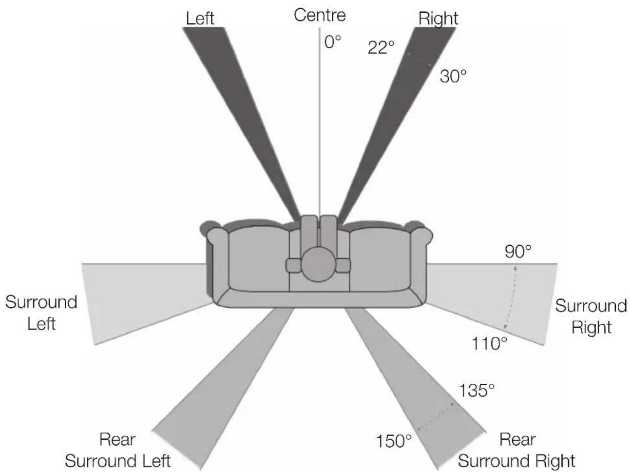
Optimum AV Speaker Positioning
Silver Series4
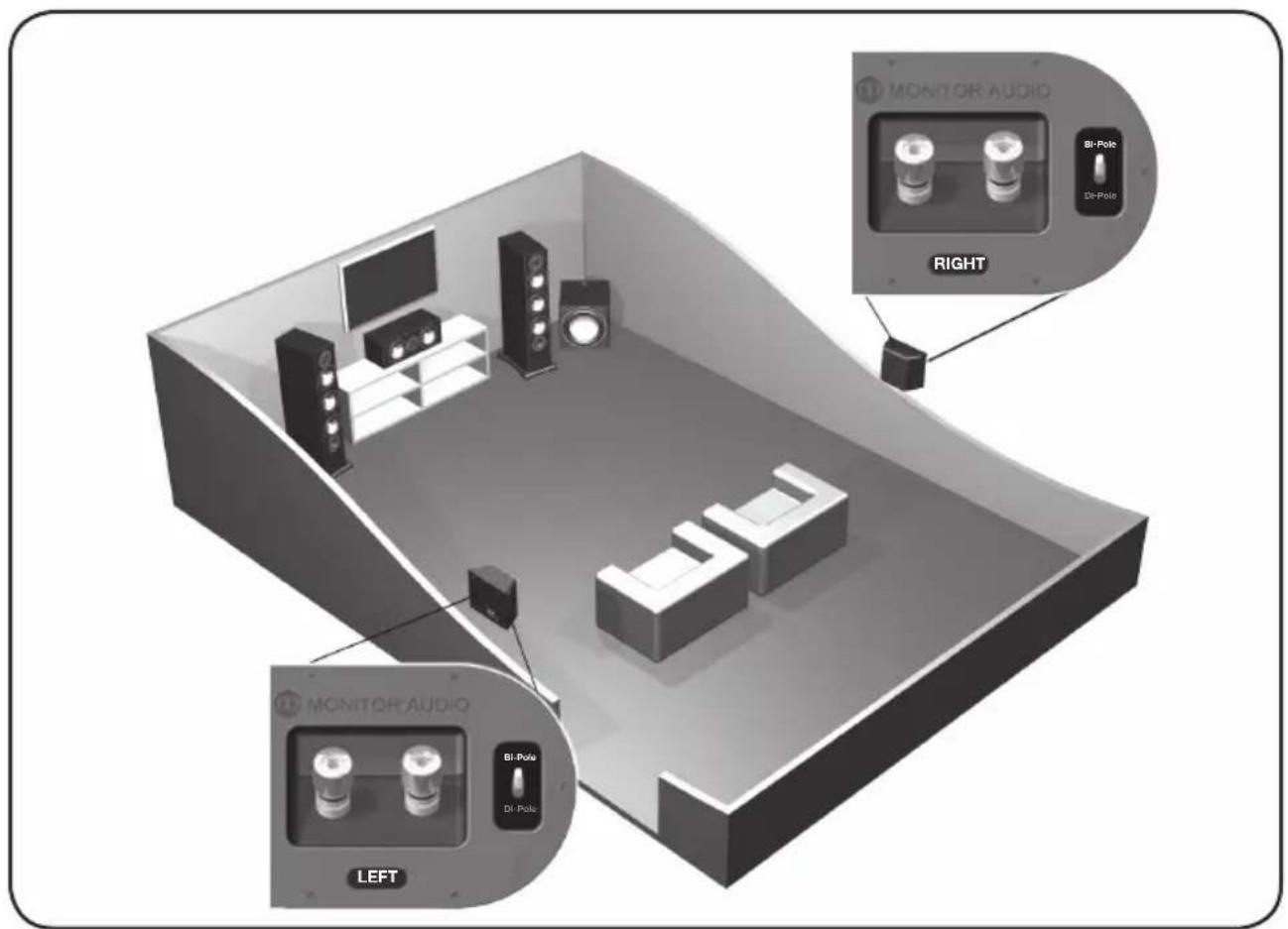
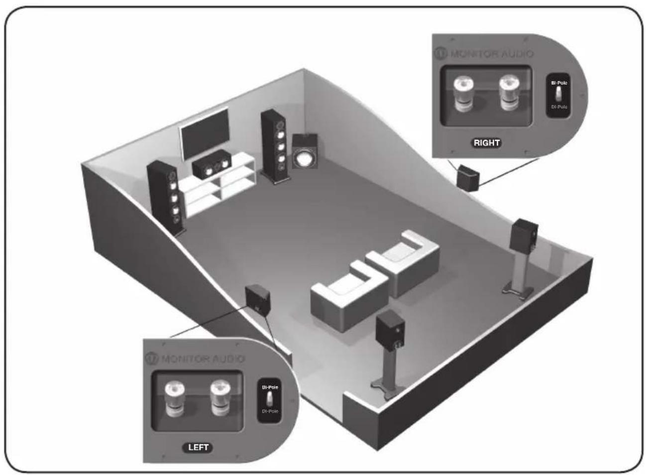
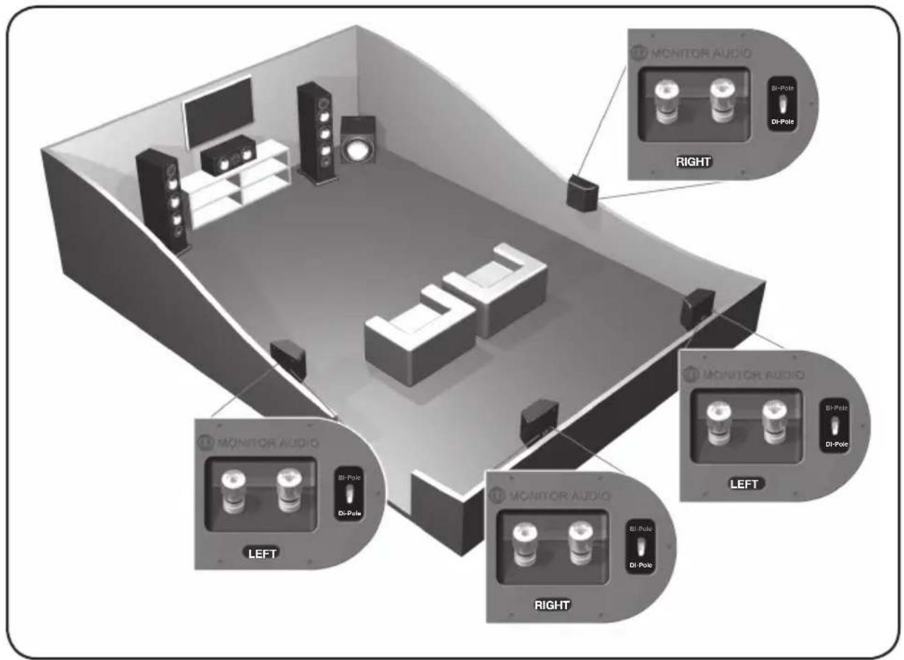
Silver FX Switch Configuration

Silver Series6
2 Channel Positioning
For use in a 2 channel system, the listening position and the loudspeakers should form an equilateral triangle. The speakers should be positioned approximately 6 - 10 feet (1.8 - 3m) apart. They ideally need to be between 8 - 18 inches (20 - 45cm) away from the rear and 3 feet (1m) from the side walls.
Experimentation is strongly advised when initially setting up your speakers, as environments and personal preference differ with each installation. If there is not enough bass, for example, then try moving your speakers closer to a wall. The opposite, if there is too much bass. Also see the information on page 11 referring to Port Bungs. If you are losing stereo imaging, try ‘toeing’ them in slightly. The sound should appear to originate from the centre point between the speakers, not the actual speakers themselves.
Setting up the Silver FX

NOTE: When using 2 pairs of Silver FX's in a 7.1 system, you need to use the Right speaker for the rear surround left and the Left speaker for the rear surround right. This is because of the tweeter phasing.
The Silver FX's are paired, but specifically, right hand and left hand units. Of which both can be configured to bi-pole (normal operation) or di-pole modes. The factory setting is bi-pole.
In bi-pole mode, all speaker units (mid/bass unit and tweeters) are in phase. This feature is designed for when the FX is set up as a rear/surround speaker in a typical 5.1 channel system, or alternatively in a 7.1 channel system without a second pair of FX's for rear/ surround duties.
In di-pole mode, the rear firing tweeters are out of phase with the other tweeter and mid/bass unit. It is best to implement this configuration when using the two pairs FX's as part of a 7.1 channel system, with the FX's taking up positions on the side and rear walls. Please note that the FX's are left and right handed. This is not an issue when used in bi-pole mode. It is essential that they are positioned correctly if used in a 7.1 channel system. Please refer to the positioning section on page 4.

NOTE: Before changing your FX's from bi-pole mode to di-pole mode, please ensure that the speaker wires are disconnected from your loudspeakers. This helps to protect your amplifier.
Fixing the Silver FX to a wall

CAUTION: You will need to determine where the Silver FX's will be fixed and the structure of the wall. For safety reasons, if you are unsure of your ability to provide a secure and safe fixing, do not attempt to fix these speakers to your wall, please obtain the services of a competent and qualified trades person.

CAUTION: Ensure that there are no water pipes or electricity cables running behind where the wall brackets are going to be secured. Work from secure steps and avoid trailing wires.
We do not supply wall fixing screws and plugs with the FX's. Please use suitable fixings for the type of wall construction the FX's will be fixed to.
To fix your FX's to the wall, we would recommend using the wall fixing template enclosed within the packaging carton
Plinth Fixing
Floor standing models only
The Silver 6, 8 & 10's are supplied with plinths to improve stability and acoustic response. The plinths are secured in place by using the supplied M10 bolts. They are not essential should space be at a premium. If you choose not to use the plinths, fit the spiked feet direct to the cabinet.
Before you fit the plinth ensure the floor area is clear of any hard/sharp objects. To fit the plinth turn the cabinet over so that the bottom is facing upwards. Place the plinth onto the cabinet ensuring it is orientated correctly, lining up the bolt holes in the plinth with the inserts in the cabinet. Using the bolts, secure the plinth to the cabinet. Tighten them up gradually at first and ensure the plinth is fitted securely to the cabinet. Fit the feet to the plinth before turning the loudspeaker back over. (Please read the instructions opposite). The spikes are used to improve sound quality and bass performance
Grilles
All of the Silver Series speakers come with grilles covered in acoustically transparent cloth. The grilles are held invisibly in place by magnets in both the grille and the cabinet (except the FX).
To fit them, firstly ensure they are the correct way up (badge at the bottom) and offer them up to the cabinet. The magnets should then pull it into position.
The FX comes with the grilles factory fitted. If you wish to remove them, carefully prize them away from the cabinet with the tips of your fingers. There are three separate grilles fitted to each cabinet.

CAUTION: Always remove grilles before lifting or moving the speakers.
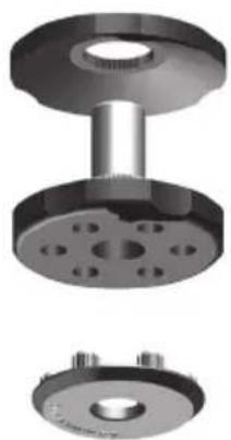
The Silver Series spiked foot incorporates a spike for use on carpeted floors and also, a soft polymer pad for use on wooden or tiled floors.
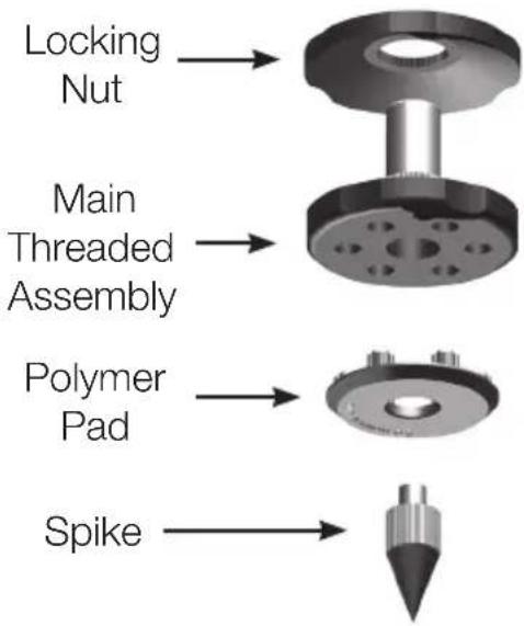
flowchart
graph TD
    A["Locking Nut"] --> B["Main Threaded Assembly"]
    B --> C["Polymer Pad"]
    C --> D["Spike"]
Please ensure there are no hidden wires under the carpet that could be damaged by the spikes.
The foot comes fully assembled for use on carpeted floors. All that is required is fixing into the plinth (or cabinet if you chose not to use the plinth). This is achieved by screwing the feet fully into the 4-threaded inserts in the underside of the plinth/cabinet. If your carpet has a very thick pile, remove the soft polymer pad from the foot to ensure the spike goes right through the carpet into the floor. With great care turn your cabinet the right way up. Place the cabinet in your desired location, and check that it is level on all sides. If it is slightly off level, unscrew the spike at the lowest point and check again. Continue this process until the cabinet is fully level. Use the locking nut on the foot to fix it in place and to stop any unwanted vibrations.
For Wooden/ Hard Floors
Floor standing models only
For use on solid floors or where spikes are inappropriate, it is possible to use the foot without the spike. To use the foot in this manner carefully grip the knurled portion of the spike and rotate anti clockwise and unscrew the spike fully.
You may find it easier to first remove the polymer pad so as to gain more purchase on the spike. The pad should be replaced before carrying out the levelling operation described above.
natural_image
3D mechanical assembly diagram showing three views of a flange component (top, front, side) with bolt holes and mounting holes (no text or symbols)Connecting Speaker Cables
Bare Wire Connection
Unscrew the binding posts and pass the bare wire through the through-hole and tighten the binding post to clamp the wire in place.
natural_image
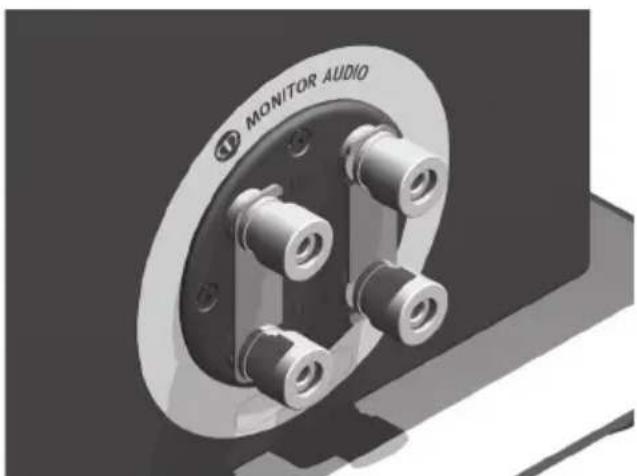
3D rendering of a mechanical component with labeled 'MONITOR AUDIO' and bolt holes (no other text or symbols)Single Wire
Connect the banana plugs/ bare wire to the terminals. Connect to either the top, bottom or diagonally (experimentation is advisable to achieve the preferred results).

Leave the terminal links in place.
natural_image
3D rendering of a mechanical component labeled 'MONITOR AUDIO' with multiple cylindrical pins (no additional text or symbols)Banana Plugs
Remove the red and black plastic plugs from the terminals and insert the banana plugs into the holes that are revealed.
A knife blade of flat blade screwdriver may be required to gain purchase on the plugs.

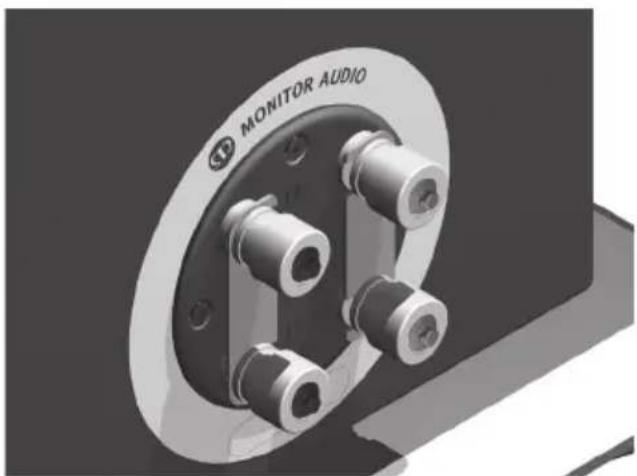
Bi-Wire/ Bi-Amp
Connect the banana plugs/ bare wire to the top and bottom terminals (positive to positive and negative to negative).

The terminal links MUST be removed.

natural_image
Close-up of a mechanical component with metallic fittings and mounting holes, labeled 'MONITOR AUDIO' (no other text or symbols visible)Port bungs

WARNING: Care must be taken not to insert the port bungs too far into the port, as this may result in the foam bung being lost inside the cabinet.
If the loudspeaker is to be installed in a small room, typically 9 sqM (80 sqFT), or a room known to reproduce accentuated bass response, it may be desirable to fit port bungs. However, experimentation is recommended with positioning of the loudspeaker in the room prior to fitting. To optimise a loudspeakers performance, ensure it is not positioned too close to a wall or near the corners of a room (refer to the suggestions on pages 4 and 7).
If room aesthetics or layout predetermine speaker positioning, or experiencing the presence of accentuated bass, please move on and read point 1 for the Silver 1 and 2 and point 2 for the Silver 6, 8 and 10.
-
Where bookshelf/ stand-mount speakers (Silver 1 & 2) are to be sited in close proximity of less than 8 inches/ 20cm to a rear wall (such as on a bookshelf, positioned in a cabinet or on a stand close to a wall), we recommend fitting port bungs to the ports. This will reduce the bass ‘boom’ and assist the loudspeakers to reproduce their best performance under these environmental conditions.
-
Where floor-standing loudspeakers (Silver 6, 8 & 10) are to be sited in close proximity of less than 18 inches/45cm to a rear wall, we recommend fitting the port bungs. This will reduce the bass 'boom' and assist the loudspeakers to reproduce their best performance under these environmental conditions.
What is Bass Boom?
Bass ‘Boom’ (sometimes termed as overhang) is generally caused when bass energy from the loudspeaker ‘excites’ room modes and causes an accentuation at a particular frequency, or number of frequencies
When fitting port bungs the overall bass extension will not be reduced, however bass energy/ output around the port tuning frequency will be reduced. This has the effect of reducing bass ‘boom’ while increasing bass clarity and apparent agility.
Experimentation is highly recommended.
Running In
The speakers will require a level of “running in” before they have reached the optimum. The running in process for the Silver Series will be approximately 60 - 70 hours of playback. During the running in process, it is recommended not to push the loudspeakers to high levels as this can cause damage to them. During this time, you will notice the sound open up and become clearer, tighter and a lot more controlled.
| MODEL SILVER 1 | SILVER 2 | SILVER 6 | SILVER 8 | SILVER 10 | SILVER Center | SILVER FX | ||||
| System Format | 2 - way 2 - way 2 | 3% way 3 - way 3 - way 2 | way (M - T - M) 2 - way | |||||||
| Frequency Response | 45HZ - 35KHZ 40HZ - | 35KHZ 35HZ - 35KHZ 32HZ - 35KHZ 30HZ - 35KHZ | 45HZ - 35KHZ 60HZ - 35KHZ | |||||||
| Nominal Impedance | 87dB 88dB 90dB 90dB 90dB 87dB | |||||||||
| Maximum S.P.L. | 110.8DBA (par) | 112.6DBA (par) | 115.sDBA (par) | 116.8DBA (par) | 117.8DBA (par) | 112.5DBA | 110.1DBA (par) | |||
| System Horizontal | 8ohms 8ohms 8ohms 4ohms 4ohms 8ohms 8ohms | |||||||||
| Nominal Impedance | 8ohms 8ohms 8ohms 4ohms 4ohms 8ohms 8ohms | |||||||||
| System Format | 2 - way 2 - way 2 | 3% way 3 - way 3 - way 2 | way (M - T - M) 2 - way | |||||||
| Frequency Response | 45HZ - 35KHZ 40HZ - | 35KHZ 35HZ - 35KHZ 32HZ - 35KHZ 30HZ - | 35KHZ 45HZ - 35KHZ 60HZ - 35KHZ | |||||||
| System Horizontal | 87dB 88dB 90dB 90dB 90dB 87dB | |||||||||
| Maximum S.P.L. | 110.8DBA (par) | 112.6DBA (par) | 115.sDBA (par) | 116.8DBA (par) | 117.8DBA (par) | 112.sDBA | 110.1DBA (par) | |||
| Maximum Impedance | 8ohms 8ohms 8ohms 4ohms 4ohms 8ohms 8ohms | |||||||||
| Nominal Impedance | 87dB 88dB 90dB 90dB 90dB 87dB | |||||||||
| System Horizontal | 87dB 88dB 90dB 90dB 90dB 87dB | |||||||||
| Maximum Impedance | 87dB 88dB 90dB 90dB 90dB 87dB | |||||||||
| System Horizontal | 87dB 88dB 90dB 90dB 90dB 87dB | |||||||||
| Maximum Impedance | 87dB 88dB 90dB 90dB 95dB | |||||||||
| System Horizontal | 87dB 88dB 90dB 90dB 87dB | |||||||||
| Maximum Impedance | 87dB 88dB 90dB 90dB 87dB | |||||||||
| System Horizontal | 87dB 88dB 90dB 90dB 87dB | |||||||||
| Maximum Impedance | 87dB 88dB 90dB 90dB 87dB | |||||||||
| System Horizontal | 87dB 88dB 90dB 95dB | |||||||||
| System Horizontal | 87dB 88dB 90dB 90dB 87dB | |||||||||
| Maximum Impedance | 87dB 88dB 90dB 90dB 87dB | |||||||||
| System Horizontal | 87dB 87dB 90dB 90dB 87dB | |||||||||
| System Horizontal | 87dB 88dB 90dB 90dB 87dB | |||||||||
| Maximum Impedance | 87dB 88dB 90dB 90dB 87dB | |||||||||
| System Horizontal | 88dB 87dB 90dB 90dB 87dB | |||||||||
| System Horizontal | 87dB 88dB 90dB 90dB 87dB | |||||||||
| Maximum Impedance | 87dB 88dB 90dB 90dB 87dB | |||||||||
| system Horizontal | 87dB 88dB 90dB 90dB 87dB | |||||||||
| System Horizontal | 87dB 88dB 90dB 90dB 87dB | |||||||||
| System Horizontal | 87dB 88dB 90dB 90dB 87dB | |||||||||
| System Horizontal | 87dB 88dB 90dB 90dB 87dB | |||||||||

MONITOR AUDIO®
design for sound
Monitor Audio Ltd.
24 Brook Road
Rayleigh, Essex
SS6 7XJ
England
Tel: +44 (0)1268 740580
Fax: +44 (0)1268 740589
Email: info@monitoraudio.co.uk
monitoraudio.com
Designed and Engineered in the
United Kingdom, made in China
© 2013. Version 1
Silver series
manuel utilisateur
Table des matières
Bicâblage/biamplification 24
Bouchons de port 25
Rodage 25
Specifications 26
Introduction
natural_image
Technical illustration of a mechanical flange assembly with three views (top, front, side), no text or symbols present.natural_image
Close-up of a mechanical component with labeled 'MONITOR AUDIO' and bolt holes (no other text or symbols visible)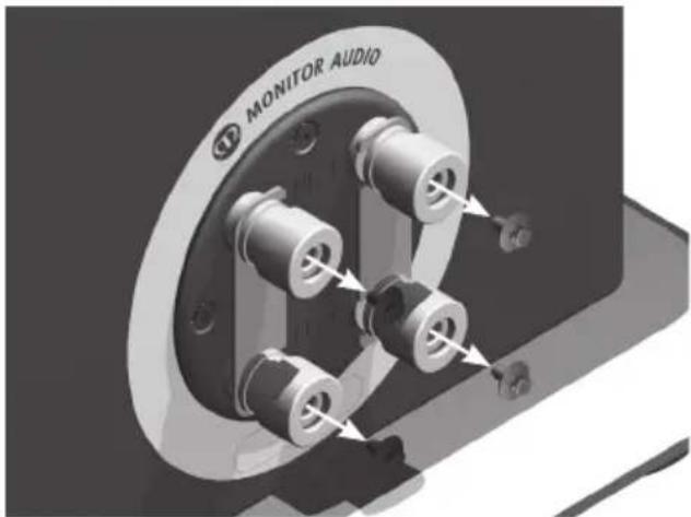
Câble unique
Bicâblage/biamplification.
natural_image
3D rendering of a mechanical component labeled 'MONITOR AUDIO' with multiple cylindrical features (no readable text beyond label)
natural_image
Close-up of a mechanical component with metallic fittings and mounting holes (no visible text or symbols)Bouchons de port

natural_image
3D mechanical assembly showing three views of a flange and bolted base (no text or symbols)natural_image
Close-up of a mechanical component with labeled 'MONITOR AUDIO' and bolt holes (no other text or symbols visible)Cavo singolo
natural_image
3D rendering of a mechanical component labeled 'MONITOR AUDIO' with multiple cylindrical features (no other text or symbols visible)
natural_image
Close-up of a mechanical component labeled 'MONITOR AUDIO' with multiple cylindrical ports and mounting holes (no readable text beyond label)natural_image
Technical illustration of a mechanical flange assembly with three views (top, front, and side), no text or symbols present.natural_image
3D rendering of a mechanical component with labeled 'MONITOR AUDIO' and bolt holes (no other text or symbols)Einzelader
natural_image
3D rendering of a mechanical component labeled 'MONITOR AUDIO' with multiple cylindrical pins (no additional text or symbols)Bananenstecker
natural_image
Close-up of a mechanical component with metallic fittings and mounting holes, labeled 'MONITOR AUDIO' (no other text or symbols visible)
natural_image
3D mechanical assembly diagram showing three views of a flange component (top, front, side) with no visible text or symbols.natural_image
3D rendering of a mechanical component with labeled 'MONITOR AUDIO' and bolt holes (no other text or symbols)Cableado sencillo
natural_image
3D rendering of a mechanical component labeled 'MONITOR AUDIO' with multiple cylindrical pins (no additional text or symbols)
natural_image
Close-up of a mechanical component with metallic fittings and mounting holes, labeled 'MONITOR AUDIO' (no other text or symbols visible)Tapones de puertos

natural_image
3D mechanical assembly diagram showing three views of a flange component (top, front, side) with bolt holes and mounting holes (bottom), no text or symbols present.natural_image
3D rendering of a mechanical component labeled 'MONITOR AUDIO' with multiple cylindrical pins (no additional text or symbols)Fio simples
natural_image
3D rendering of a mechanical component labeled 'MONITOR AUDIO' with multiple cylindrical pins (no additional text or symbols)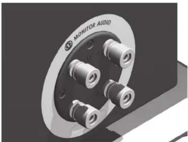
natural_image
Close-up of a mechanical component with metallic bolts and a labeled 'MONITOR AUDIO' (no other text or symbols visible)Tampões das portas

natural_image
Technical illustration of a mechanical flange assembly with three views (top, front, side), no text or symbols present.natural_image
3D rendering of a mechanical component labeled 'MONITOR AUDIO' with multiple cylindrical pins (no additional text or symbols)Enkele draad
natural_image
3D rendering of a mechanical component labeled 'MONITOR AUDIO' with multiple cylindrical pins (no additional text or symbols)Banaanstekkers
natural_image
Close-up of a mechanical component with metallic bolts and a labeled 'MONITOR AUDIO' (no other text or symbols visible)Poortstoppen

natural_image
Technical illustration of three mechanical flange components with bolt holes (no text or symbols)连接扬声器电线
裸线连接
natural_image
3D rendering of a mechanical component with labeled 'MONITOR AUDIO' and bolt holes (no other text or symbols)单线
natural_image
3D rendering of a mechanical component labeled 'MONITOR AUDIO' with multiple cylindrical pins (no additional text or symbols)
natural_image
Close-up of a mechanical component with metallic fittings and mounting holes, labeled 'MONITOR AUDIO' (no other text or symbols visible)风管塞子

Email: info@monitoraudio.co.uk
monitoraudio.com
Designed and Engineered in the
United Kingdom, made in China
© 2013. Version 1
Silver series
natural_image
3D mechanical assembly diagram showing two views of a flange and a bolted flange (no text or symbols)natural_image
Close-up of a mechanical component with labeled 'MONITOR AUDIO' and bolt holes (no other text or symbols visible)Один провод
natural_image
3D rendering of a mechanical component labeled 'MONITOR AUDIO' with multiple cylindrical pins (no additional text or symbols)
natural_image
Close-up of a mechanical component with metallic bolts and a labeled 'MONITOR AUDIO' (no other text or symbols visible)Заглушки портов

Email: info@monitoraudio.co.uk
monitoraudio.com
Email: info@monitoraudio.co.uk
monitoraudio.com
Designed and Engineered in the
United Kingdom, made in China
© 2013. Version 1
- Introduction
- New bass and mid-range drivers
- New tweeter
- Other design features
- Silver 1
- Silver 2
- Silver 6
- Silver 8
- Silver 10
- Silver Centre
- Silver FX
- Setting Up AV Positioning
- Channel Positioning
- Setting up the Silver FX
- Fixing the Silver FX to a wall
- Plinth Fixing
- Grilles
- For Wooden/ Hard Floors
- Connecting Speaker Cables
- Bare Wire Connection
- Single Wire
- Banana Plugs
- Bi-Wire/ Bi-Amp
- Port bungs
- What is Bass Boom?
- Running In
- MONITOR AUDIO®
- design for sound
- Silver series
- Table des matières
- Câble unique
- Bicâblage/biamplification.
- Bouchons de port
- Cavo singolo
- Einzelader
- Bananenstecker
- Cableado sencillo
- Tapones de puertos
- Fio simples
- Tampões das portas
- Enkele draad
- Banaanstekkers
- Poortstoppen
- 连接扬声器电线
- 裸线连接
- 单线
- 风管塞子
- Один провод
- Заглушки портов
Brand : MONITOR AUDIO
Model : Silver 6
Category : Speaker