Helios4 900 Murale - Basket ROBLIN - Free user manual and instructions
Find the device manual for free Helios4 900 Murale ROBLIN in PDF.
User questions about Helios4 900 Murale ROBLIN
0 question about this device. Answer the ones you know or ask your own.
Ask a new question about this device
Download the instructions for your Basket in PDF format for free! Find your manual Helios4 900 Murale - ROBLIN and take your electronic device back in hand. On this page are published all the documents necessary for the use of your device. Helios4 900 Murale by ROBLIN.
USER MANUAL Helios4 900 Murale ROBLIN
Instructions for use and installation
Cooker Hood

natural_image
Metallic stainless steel air duct or chimney with a flat top and curved base (no text or symbols visible)Esprit Centrale
F SOMMAIRE
RACCORDEMENT ÉLECTRIQUE
CONSEILS D'INSTALLATIONS
POSE DE L'APPAREIL
FONCTIONNEMENT
CONSEILS D'UTILISATIONS
ENTRETIEN
GARANTIE ET SERVICE APRÈS-VENTE
REMARQUES
GB CONTENTS
ELECTRICAL WIRING
INSTALLATION ADVICE
FITTING THE APPLIANCE
OPERATION
USEFUL HINTS
MAINTENANCE
GUARANTEE AND AFTER-SALES-SERVICES
REMARKS
D INHALT
NETZANSCHLUSS
MONTAGEHILFEN
MONTAGE DES GERÄTES
BETRIEB DES GERÄTES
NUTZUNG
Thank you for buying a Roblin product which has been manufactured to the highest quality standards to meet your requirements.
We recommend you carefully read this booklet in which you will find instructions for installation, hints for use and maintenance.
The Instructions for Use apply to several versions of this appliance. Accordingly, you may find descriptions of individual features that do not apply to your specific appliance.
1 ELECTRICAL
- This cooker hood is fitted with a 3-core mains cable with a standard 10/16A earthed plug.
• Alternatively the hood can be connected to the mains supply via a double-pole switch having 3mm minimum contact gap on each pole. - Before connecting to the mains supply ensure that the mains voltage corresponds to the voltage on the rating plate inside the cooker hood.
- Technical Specification: Voltage 220-240, single phase \~50/60Hz.
2 INSTALLATION ADVICE
- Ensure the cooker hood is fitted in compliance with the recommended fixing heights.
- To ensure the safe operation of this cooker hood, we recommend that the hood should not be fitted below 65cm (for electric) or (70cm for gas) the measurements taken from the surface of the cooking appliance to the underside of the cooker hood.
- It is a possible fire risk if the hood is not sited as recommended.
- To ensure the best results, the cooking fumes should be able to rise naturally towards the inlet grilles on the underside of the cooker hood and the cooker hood should be positioned away from doors and windows, which will create turbulence.
- Ducting
- If the room where the hood is to be used contains a fuel-burning appliance such as a central heating boiler then its flue must be of the room sealed or balanced flue type.
- If other types of flue or appliances are fitted ensure that there is an adequate supply of fresh air to the room. Ensure the kitchen is fitted with an airbrick, which should have a cross-sectional measurement equivalent to the diameter of the ducting being fitted, if not larger.
- The ducting system for this cooker hood must not be connected to any existing ventilation system, which is being used for any other purposes or to a mechanically controlled ventilation ducting.
- The ducting used must be made from fire retardant materials and the correct diameter must be used, as incorrect sized ducting will affect the performance of this cooker hood.
- When the cooker hood is used in conjunction with other appliances supplied with energy other than electricity, the negative pressure in the room must not exceed 0.04 mbar to prevent the fumes from combustion being drawn back into the room.
- The appliance is for domestic use only and should not be operated by children or people who are infirm without supervision.
- This appliance must be positioned so that the wall socket is accessible.
- This appliance is not intended for use by persons (including children) with reduced physical, sensory or mental capabilities, or lack of experience and knowledge, unless they have been given supervision or instruction concerning use of the appliance by a person responsible for their safety.
Children should be supervised to ensure that they do not play with the appliance.
3 FITTING
Any permanent electrical installation must comply with the latest regulations concerning this type of installation and a qualified electrician must carry out the work. Non-compliance could cause serious accidents or injury and would deem the manufacturers guarantee null and void.
IMPORTANT - The wires in this mains lead are coloured in accordance with the following code :
- green / yellow : earth
- blue : neutral
- brown : live
As the colours of the wires in the mains lead of this appliance may not correspond with the coloured
markings identifying the terminals in your plug, proceed as follows.
- The wire which is coloured green and yellow must be connected to the terminal in the plug which is marked with the letter E or by the earth symbol or coloured green or green and yellow.
- The wire which is coloured blue must be connected to the terminal which is marked with the letter N or coloured black.
- The wire which is coloured brown must be connected to the terminal which is marked with the letter L or coloured red.
ATTENTION: Do not forget to use adequate plugs to the support brackets. Enquire after the manufacturers. Do an embedding if necessary. The manufacturer accepts no responsibility in case of a faulty hanging due to the drilling and the setting up of plugs.
1) Unpack the hood parcel.
• LAYING OUT BEFORE FITTING THE HOOD
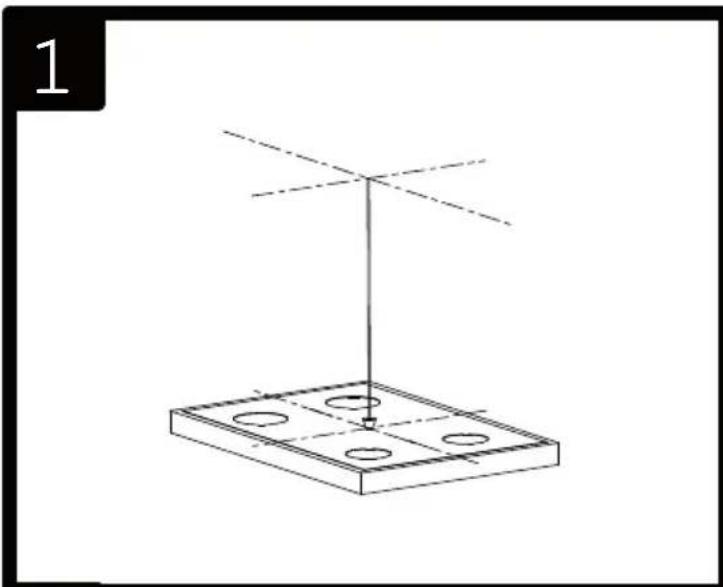
2) Mark the centre of the cooking appliance onto the ceiling with a plumb line. Draw the horizontal axes running parallel to the stove top onto the ceiling as illustrated Fig. 1.
3) Place the drill gauge centred on the axes aligning the axes on the drill gauge centrally over these axes as illustrated Fig. 2b.
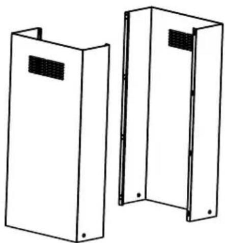
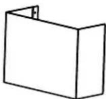
4) Remove the self-tapping screws, which fix the chimney item 7 to the metal frame bracket as illustrated in Fig. 2a and then remove both sides of the upper chimney stacks.
• FITTING THE CANOPY BRACKET
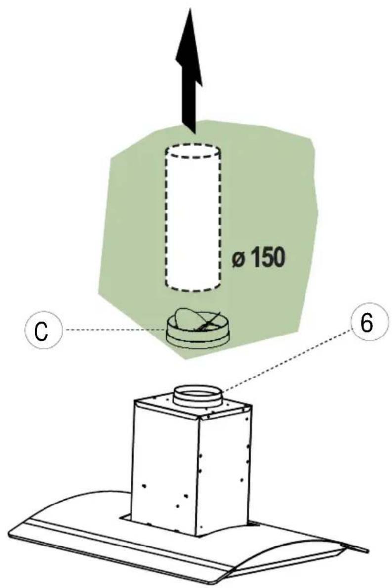
5) Mark the positions on the ceiling for : - The cut-out for the ducting ∅ 150 mm in the extraction mode and ∅ 200 mm in the remote mode when ducting runs through the ceiling.
- The mains supply cords.
- The 4 fixing holes for ∅ 10 mm nuts and bolts.
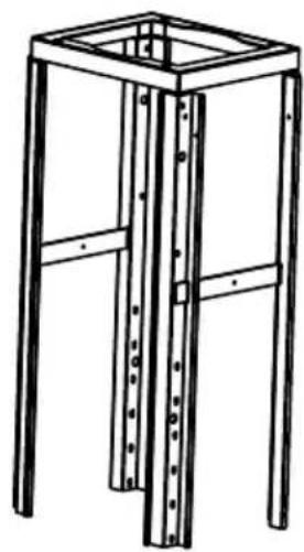
Drill the different holes with the appropriate masonry bit. When fixing the cooker hood to a plasterboard ceiling ensure it is reinforced as illustrated in Fig. 3 and attach using four ∅10mm nuts and bolts; ensuring the bolts as sleeved between the plasterboard and the joist supports to prevent the ceiling being damaged when the bolts are tightened up.
If the ceiling is concrete, use eight ∅ 10 mm steel rawl bolts. Plastic rawl plugs must not be used.
6) Remove the deflector Fig. 4.
7) The height of the cooker hood can be adjusted in 50 mm stages. 650 mm when fitting above an electric hotplate and 700 mm when fitting above a gas hotplate. Select the height required using the measurements illustrated in Fig. 5 & 6 and fix the metal diffuser to the frame of the chimney brackets using the height 5 x 10T hexagonal headed screws. A drawing on the drill gauge defines the positioning for the controls.
Attention: 2 persons are necessary to secure this operation.
8) Check the vertical of the chimney.
- DUCTING
The hood is more effective when used in the extraction mode (ducted to the outside). When the cooker hood is ducted to the outside, charcoal filters are not required.
The ducting used must be 150 mm (6 INS), rigid circular pipe and must be manufactured from fire retardant material, produced to BS.476 or DIN 4102-B1. Wherever possible utilise rigid circular pipe which has a smooth interior, rather than the expanding concertina type ducting.
Maximum length of ducting run:
- 4 metres with 1 x 90° bend.
- 3 metres with 2 x 90° bends.
- 2 metres with 3 x 90° bends.
The above assumes our 150 mm (6 INS) ducting is being installed. Please note ducting components and ducting kits are optional accessories and have to be ordered, they are not automatically supplied with the chimney hood.
IN THE EXTRACTION MODE:
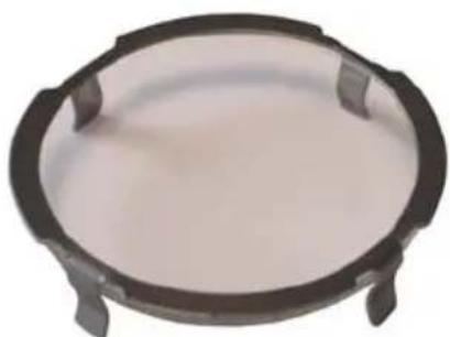
a. Fit the non-return backflow flaps C over the round outlet item 6 on top of the canopy while pressing down until they snap into position, and then connect the ducting 150mm (6 INS) and secure the connections with appropriate clamping rings or adhesive tape (Fig. 8).
b. Before fitting the chimney to the canopy make the electrical connection as described in the section titled ELECTRICAL.
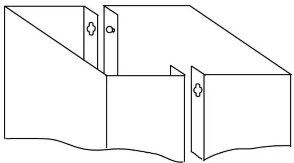
c. Each top and lower chimney stack consists of two sections. Place the top chimney with the slops facing downwards (Fig. 6c - item 7a) when installing the ducting version and secure the chimney stacks to the brackets using the M4 screws provided.
d. Check the vertical of the chimney.
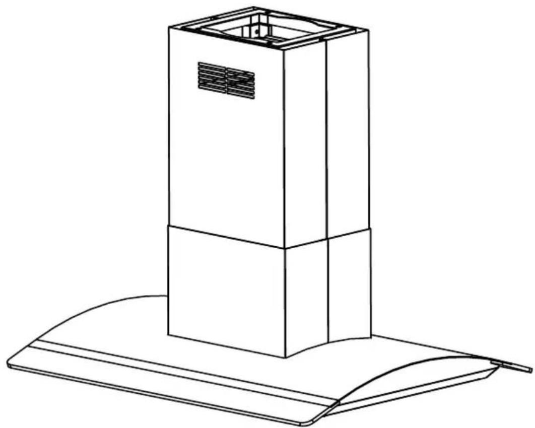
e. Place the lower chimney 7b as illustrated in Fig 9 &10.
IN THE RECIRCULATION MODE:
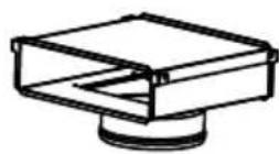
a. Fit the recirculation spigot R onto the chimney bracket using the same fixing screws Fig.6a.
b. Connect the ducting 150mm (6 INS) not provided between motors item 6 and the recirculation spigot and secure the connections with appropriate clamping rings or adhesive tape (Fig. 6c).
c. Make the electrical connection as described in the section titled ELECTRICAL.
d. Each top and lower chimney stack consists of two sections. Place the top chimney with the slops facing upwards (Fig. 6c - item 7a) when installing the recirculation version and secure the chimney stacks to the brackets using the M4 screws provided.
e. Check the vertical of the chimney.
f. Place the lower chimney 7b as illustrated in Fig 9 &10.
• FITTING THE CANOPY ONTO THE CHIMNEY
9) Check the connectors of the motor as illustrated in Fig. 11.
10) Test the lights and the fan motor.
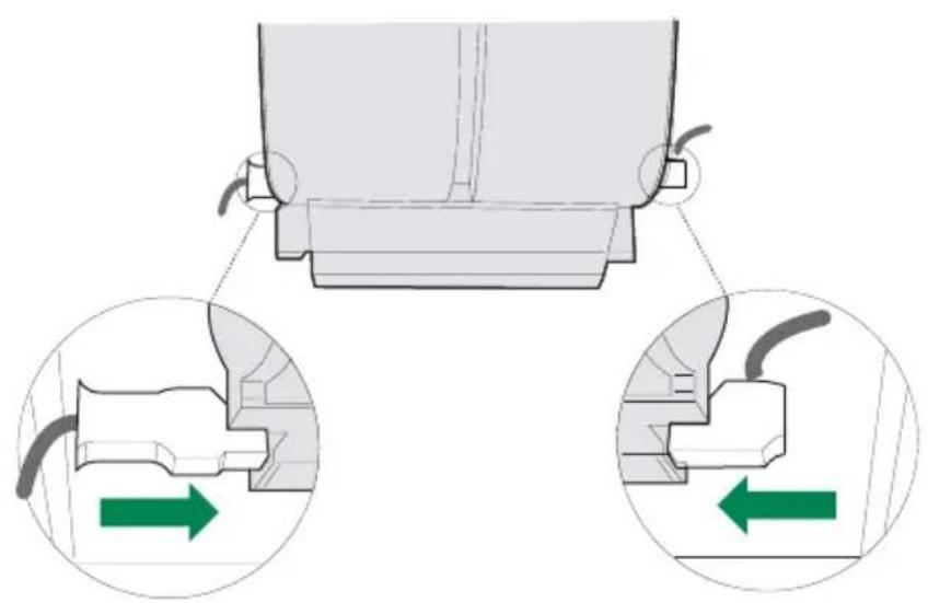
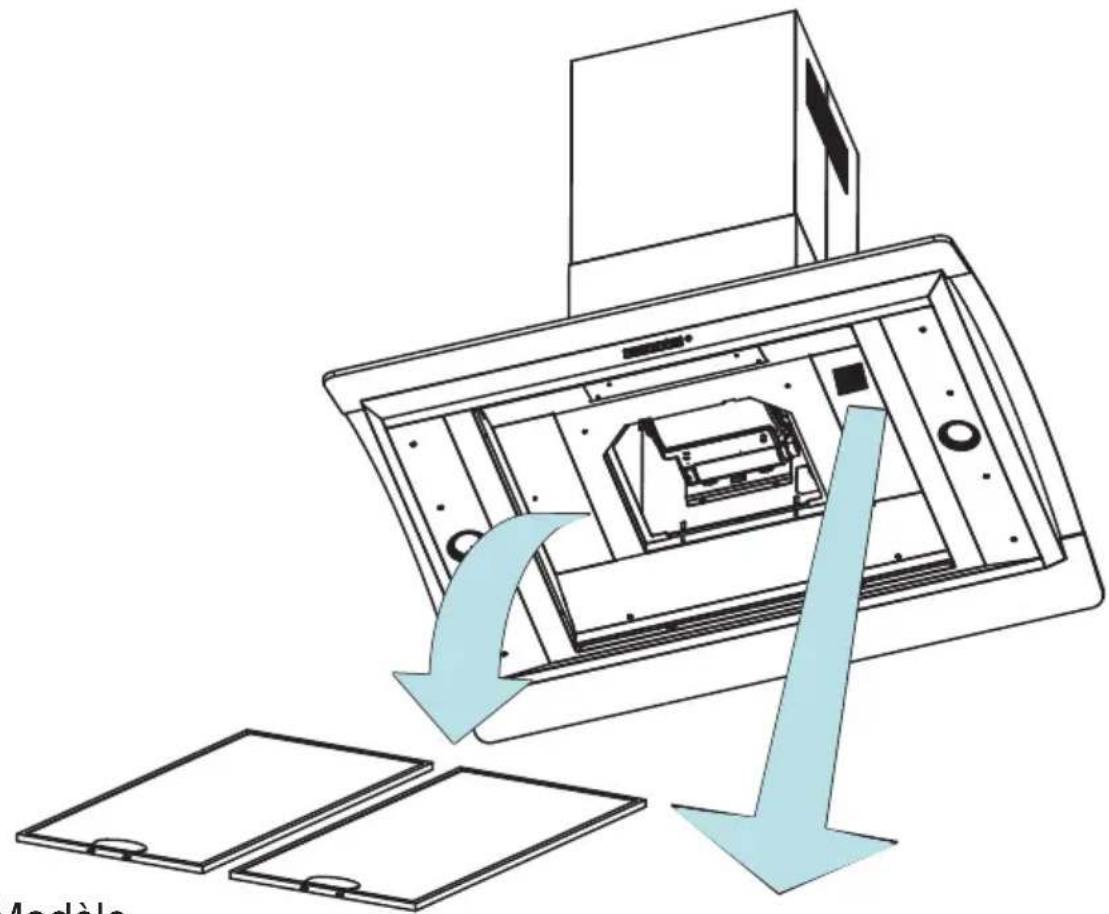
11) Remove the metal grease filters. Insert the charcoal filter into the base of the motor housing and secure the filter with two securing straps A as illustrated Fig. 6d.
12) Fit the metal grease filters.
4 OPERATION
text_image
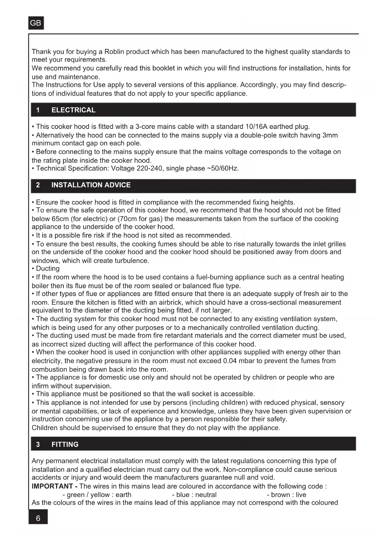
Led 1 On / Off Light Led 2 On / Off Motor Led 3 Speed control Led 4 Intensive speed Led 5 Receiver Remote control (Option) MaxA - EXTRACTION OR RECYCLING : Your cooker hood is supplied in the extraction mode. To use the cooker hood in the recycling mode re-programme the hood as follows:
Starting in the recycling mode (the contaminated air passes into the hood through the grease filters and the purifying activated charcoal filter and back out into the kitchen through grilles).
Press the ‘+’ button (while the motor and lights are switched ‘OFF’) until the five LED lights will flash twice to indicate confirmation that the cooker hood is in the recycling mode.
Reverting to the extraction mode (The cooker hood is ducted to the outside).
Press the ‘+’ button (while the motor and lights are switched ‘OFF’) until the five LED lights will flash once to indicate confirmation that the cooker hood is in the extraction mode.
B - BASIC INSTRUCTIONS
Lighting
Press LED button 1 to switch 'ON' the lights and the LED will illuminate to confirm the lights are switched 'ON'.
Motor
Press LED button 2 to switch 'ON' the fan motor (and adjust the speed of the fan motor by pressing the LED button '+' and '-' ) and the LED lights 2, 3 and 4 will illuminate. The fan speed will be increased if constant pressure is kept on the (+) button.
LED 2 : Minimum speed - cooking with one pan or simmering
LED 2 & 3 : Medium speed - normal cooking with up to 4 pans
LED 2, 3 & 4 : Maximum speed - frying and cooking foods with strong odours
Press LED button 5 to obtain the boost position for maximum effect and the LED will illuminate to confirm fan is switched 'ON'.
C - COMPLEMENTARY INSTRUCTIONS
- Boost speed :
To obtain the best performance it is advisable to switch 'ON' the cooker hood a few minutes (in the boost setting) before you start cooking. To program the complementary function, proceed as follows:
- Press LED button 2 to switch 'ON' the fan motor and adjust the speed of the fan by pressing the LED button '+' and '-''. You should keep applying pressure to the '+' and '-' button until the required speed is selected.
- Press LED button 5 (boost speed) to switch 'ON' the fan motor in the boost setting. Press LED button 5 to switch 'OFF' the boost setting immediately.
It is advisable too that you should leave it running in the boost setting for approximately 5 minutes after finishing.
- Pre-set stop of the boost speed :
A pre-set stop after 5 minutes of the boost speed is available.
Your cooker hood is supplied with a deactivated pre-set stop of the boost speed. To use the cooker hood with a pre-set stop of the boost speed re-programme the hood as follows:
The lights and the fan motor should be switched 'OFF' to set the timer.
Push the LED button '-' until the LED lights will flash :
One flash of the LED lights 2,3, and 4 = function is switched 'OFF'.
Two flashes of the LED lights 2,3, and 4 = function is switched 'ON'.
While the 5 minutes timer is running, It is available to stop immediately the boost speed by pressing the led button 5.
While the 5 minutes timer is running, the indication of saturation of the filters is switched 'OFF'.
If a pre-set stop for the hood is switched 'ON' and the 5 minutes timer is still running, the boost speed will be switched 'OFF' together with the pre-set stop for the hood after the count down of 5, 10 or 15 minutes. It is available to stop the boost speed before the count down of the preset stop of the hood by pressing the led button 5.
• Pre-set stop for the hood :
This function allows you to program the cooker hood to automatically stop cooking after a pre-set period.
The lights and the fan motor should be switched 'OFF' to set the timer.
Proceed by repeatedly pressing the LED button 5 (Boost speed):
Two flashes of the LED button 1 & 5 = 5 minutes delay.
Three flashes of the LED button 1 & 5 = 10 minutes delay.
Four flashes of the LED button 1 & 5 = 15 minutes delay.
One flash of the LED button indicates the function is switched 'OFF'.
You can switch the cooker hood 'ON' and adjust the speed. The LED buttons 2, 3 and 4 will flash to indicate the fan motor is switched 'ON' and which speed has been selected.
One flash = stop after 15 minutes.
Two flashes = stop after 10 minutes.
Three flashes = stop after 15 minutes.
- Indication of saturation of the metal grease filters :
After 200 hours use, one quick flash of the LED 1 will indicate that you must clean the metal grease filters. (See chapter on 'Maintenance').
To reset the 200 hours timer back to zero requires the motor and lights must be switched 'OFF'; then and proceed as follows:
Press the LED button ‘+’ for 3 to 4 seconds and the LED lights 1,2,3, 4 and 5 will flash to confirm the programme has been reset to zero.
- Indication of saturation of the active charcoal filter :
After 400 hours use, two quick flash of the LED 1 will indicate that you must replace the active charcoal filter and clean the metal grease filters. (See chapter on 'Maintenance').
To reset the 400-hour timer the motor and lights must be switched 'OFF'.
Push the LED button ‘+’ for 10 seconds.
One flash of the LED lights 1,2,3,4 and 5 = function is switched 'OFF'.
Two flashes of the LED lights 1,2,3,4 and 5 = function is switched 'ON'.
Instructions for replacing the active charcoal filter are given in the chapter on 'Recycling'.
- Pre-set remote control handset
Your cooker hood is supplied with a deactivated remote control receiver. To use the cooker hood with a remote control re-programme the hood as follows:
Press the LED button (Lighting) '1' while the motor and lights are switched 'OFF', until the LED lights 1 will flash to confirm the programme has been activated :
One flash of the LED lights 1 = function is switched 'OFF'.
Two flashes of the LED lights 1 = function is switched 'ON'.
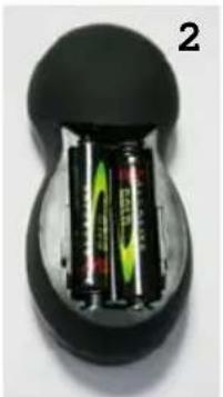
Caution, the remote control handset must be fitted with standard LR03-AAA size 1.5V zinc-carbon alkaline batteries as illustrated Fig. 7. These batteries should give a long life and constant discharge throughout their life. These batteries must be disposed of properly and could explode if damaged or exposed to heat.
Do not dispose of on fire. Dispose of batteries in the appropriate sort container to protect the environment.
5 USEFUL HINTS
• To obtain the best performance it is advisable to switch 'ON' the cooker hood a few minutes (in the boost setting) before you start cooking and you should leave it running for approximately 15 minutes after finishing.
• IMPORTANT: NEVER DO FLAMBÉ COOKING UNDER THIS COOKER HOOD
- Do not leave frying pans unattended during use as over-heated fat and oil might catch fire.
- Do not leave naked flames under this cooker hood.
- Switch 'OFF' the electric and gas before removing pots and pans.
- Ensure heating areas on your hotplate are covered with pots and pans when using the hotplate and cooker hood simultaneously.
6 MAINTENANCE
Before carrying out any maintenance or cleaning isolate the cooker hood from the mains supply. The cooker hood must be kept clean; a build up of fat or grease can be a fire hazard.
Casing
- Wipe the cooker hood frequently with a clean cloth, which has been immersed in warm water containing a mild detergent and wrung out.
- Never use excessive amounts of water when cleaning particularly around the control panel.
- Never use scouring pads or abrasive cleaners.
• Always wear protective gloves when cleaning the cooker hood.
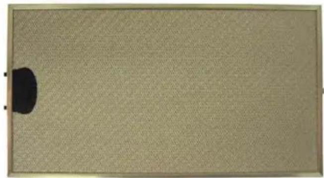
Metal Grease Filters
The metal grease filters absorb grease and dust during cooking to help keep the cooker hood clean inside. The grease filters should be cleaned once a month or more frequently if the hood is used for more than 3 hours per day.
To remove and replace the metal grease filters
- Remove the metal grease filters one at a time by releasing the catches on the filters; the filters can now be removed.
- The metal grease filters should be washed, by hand, in mild soapy water or in a dishwasher.
- Allow to dry before replacing.
Active Charcoal Filter
The charcoal filter cannot be cleaned. The filter should be replaced at least every three months or more frequently if the hood is used for more than three hours per day.
To remove and replace the filter
- Remove the metal grease filters.
- Press against the two retaining clips, which hold the charcoal filter in place and this will allow the filter to drop down and be removed.
- Clean the surrounding area and metal grease filters as directed above.
- Insert the replacement filter and ensure the two retaining clips are correctly located.
- Replace the metal grease filters.
Extraction tube.
Check every 6 months that the dirty air is being extracted correctly. Comply with local rules and regulations with regard to the extraction of ventilated air.
Lighting.
If the lamp fails to function check to ensure it is fitted correctly into the holder. If lamp failure has occurred then it should be replaced with identical replacement.
Do not replace with any other type of lamp and do not fit a lamp with a higher rating.
7 GUARANTEE AND AFTER SALES SERVICE
- In the event of any malfunction or anomaly, notify your fitter who will have to check the appliance and its connection.
- In the event of damage to the mains supply cable, this can only be replaced by at approved repair centre appointed by the manufacturer who have the necessary tools and equipment to carry out any repairs properly. Repairs carried out by other persons will invalidate the guarantee.
- Use only genuine spare parts. Should these warnings fail to be observed it could affect the safety of your cooker hood.
- When ordering spare parts quote the model number and serial number written on the rating plate, which is found on the casing behind the grease filters inside the hood.
• Proof of purchase will be required when requesting service. Therefore, please have your receipt available when requesting service as this constitutes the date from which your guarantee commenced. This Guarantee does not cover : - Damage or calls resulting from transportation, improper use or neglect, the replacement of any light bulbs or filters or removable parts of glass or plastic.
These items are considered to be consumable under the terms of this guarantee.
8 REMARKS
This appliance complies with European regulations on low voltages Directive 2006/95/CE on electrical safety, and with the following European regulations: Directive 2004/108/CE on electromagnetic compatibility and Directive 93/68 on EC marking.
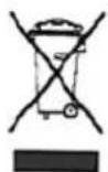
When this crossed-out wheeled bin symbol ↗ is attached to a product it means the product is covered by the European directive 2002/96/EC. Your product is designed and manufactured with high quality materials and components, which can be recycled and reused. Please inform yourself about the local separate collection system for electrical and electronic product. Please act according to your local rules and do not dispose of your old products with your normal household waste. The correct disposal of your old product will help prevent potential negative consequences for the environment and human health.
LED 2 = NIVEL MÍNIMO
LED 2 Y 3 = NIVEL INTERMEDIO
LED 2, 3 Y 4 = NIVEL MÁXIMO
3 INSTALLATIE VAN HET APPARAAT
Any permanent electrical installation must comply with the latest I.E.E. Regulations and local Electricity Board regulations. For your own safety this should be undertaken by a qualified electrician e.g. your local Electricity Board, or a contractor who is on the roll of the National Inspection Council for Electrical Installation Contracting (NICEIC).
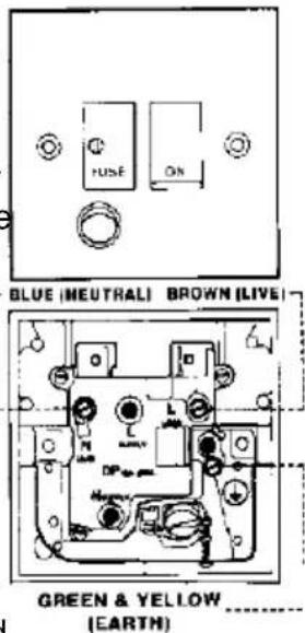
ELECTRICAL CONNECTION
Before connecting to the mains supply ensure that the mains voltage corresponds to the voltage on the rating plate inside the cooker hood.
text_image
BLUE (NEUTRAL) BROWN (LIVE) GREEN & YELLOW (EARTH)The wires in this mains lead are coloured in accordance with the following code: Green & Yellow Earth Blue Neutral Brown Live
As the colours of the wires in the mains lead of this appliance may not correspond with the coloured markings identifying the terminals in your connection unit, proceed as follows:-
This appliance is fitted with a 2 core mains cable and must be permanently connected to the electricity supply. The wire which is coloured blue must be connected via a double-pole switch having 3mm minimum contact gap on each pole. A Switched Fuse Connection Unit (EARTH) proceed as follows:
to BS.1363 Part 4, fitted with a 3 Amp fuse, is a The wire which is coloured brown must be connected recommended mains supply connection accessory to the terminal which is marked with the letter 'L' or ensure compliance with the Safety Requirements coloured red. applicable to fixed wiring instructions.
CH
MAJ (UPDATE) :14/12/12
natural_image
Simple line drawing of a wind turbine mounted on a rectangular base with circular holes, no text or symbols present.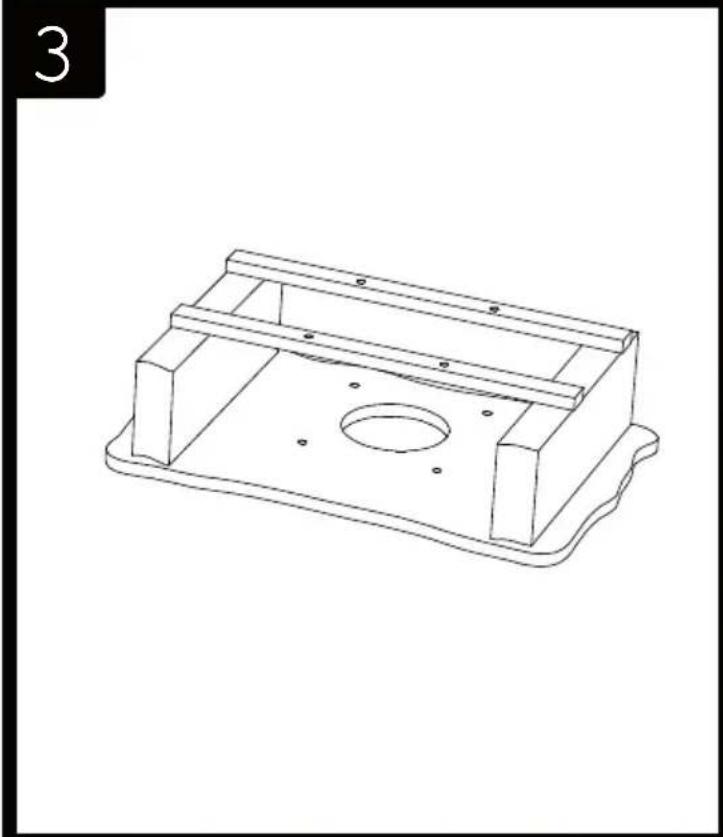
natural_image
Line drawing of a mechanical housing component with mounting holes and a central circular hole (no text or symbols)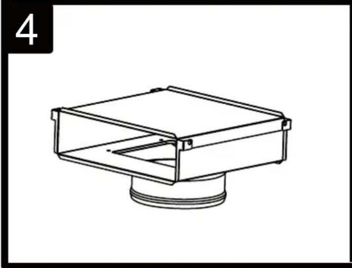
natural_image
Technical line drawing of a mechanical component with a flanged base and central housing (no text or symbols)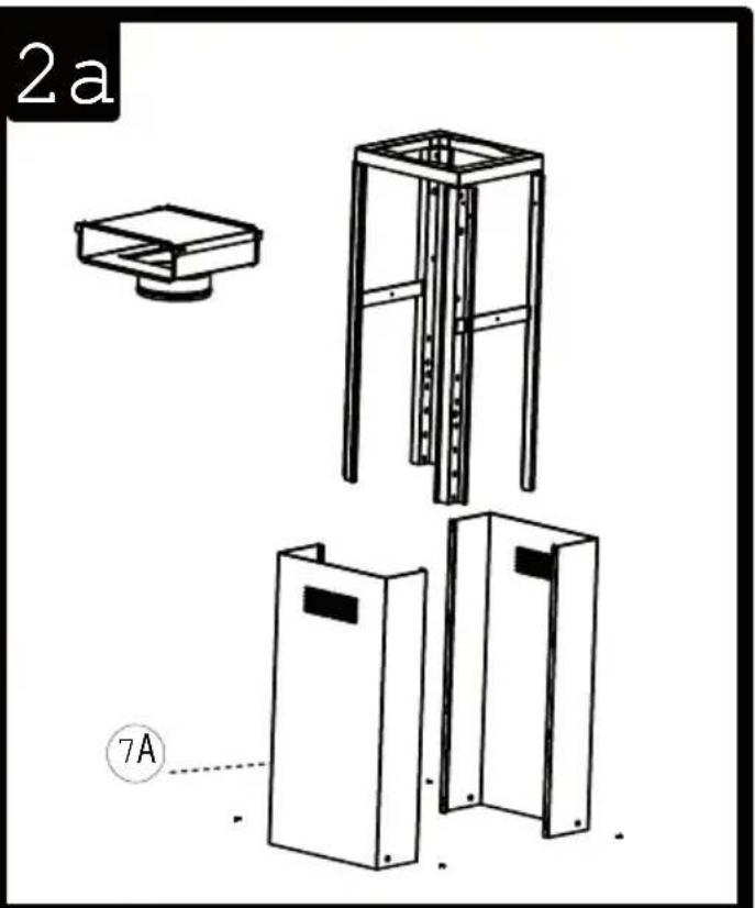
natural_image
Technical line drawings of three different mechanical or electrical components, including a bracket, frame structure, and housing (no text or symbols)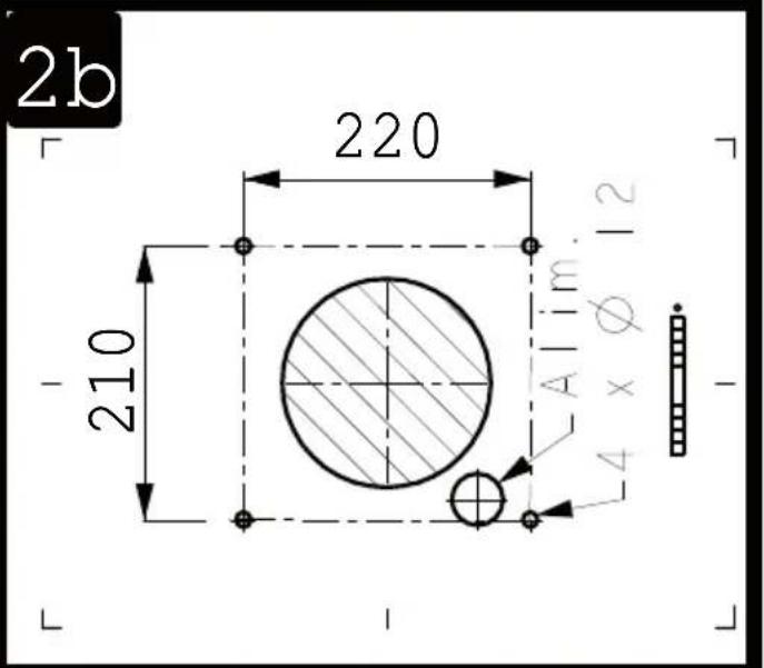
text_image
2b 220 210 Alim. 12 Ø4 x Ø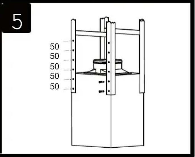
text_image
5 50 50 50 50 50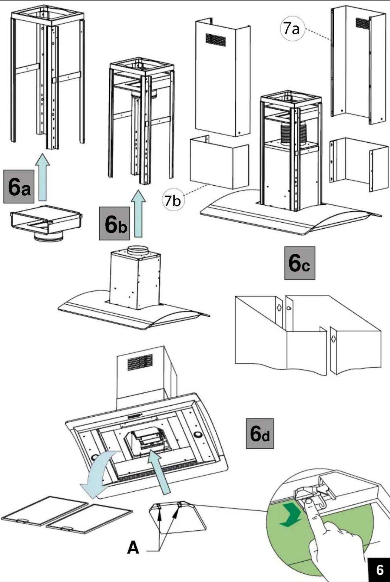
8
text_image
Ø 150 C 69
natural_image
Simple line drawing of a two-story building with windows and doors, no text or symbols present10
natural_image
Line drawing of a simple industrial chimney or enclosure with ventilation grilles and a base structure (no text or symbols)11
natural_image
Technical diagram showing mechanical assembly with two circular insets highlighting internal components (no text or symbols)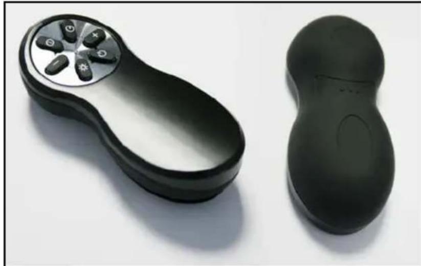
natural_image
Two black plastic electronic devices, one with a circular button and seven buttons, the other a plain outline (no text or symbols visible)
text_image
Library & Journal Introduction to Critical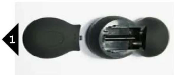
natural_image
Cross-sectional diagram of a mechanical device showing internal components (no text or symbols)LR03 / AAA / 1,5V
natural_image
Cross-sectional view of a battery pack showing internal components (no text or symbols visible)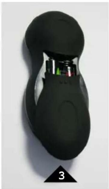
natural_image
Close-up of a black remote control device with visible internal components and a numbered label '3' at the bottom (no text or symbols on the device itself)ACCESSOIRES ACCESSORI
ACCESSORIES ACCESORIA
ZUBEHÖRE ACCESSOIRES
text_image
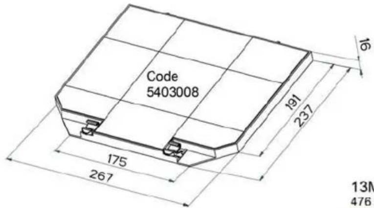
Code 5403008 191 237 175 267 13M 476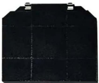
natural_image
Black rectangular battery cell with grid lines and two metal clips at top (no visible text or symbols)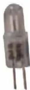
G4 12V 20W
13MC069
476 x 270 x 9 mm
natural_image
Plain beige textured surface with a small dark circular artifact on the left side (no text or symbols)Halogen Beleuchtung
Halogen Lighting
Eclairage halogène
Alogene Luci
Alógenas Luz
natural_image
Interior view of a modern double door with two light reflections and upward arrows indicating direction (no text or symbols)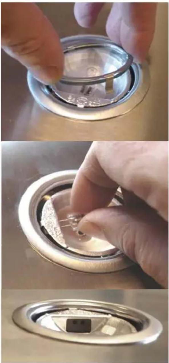
natural_image
Three-panel photo showing hands installing a small component on a metal appliance (no visible text or symbols)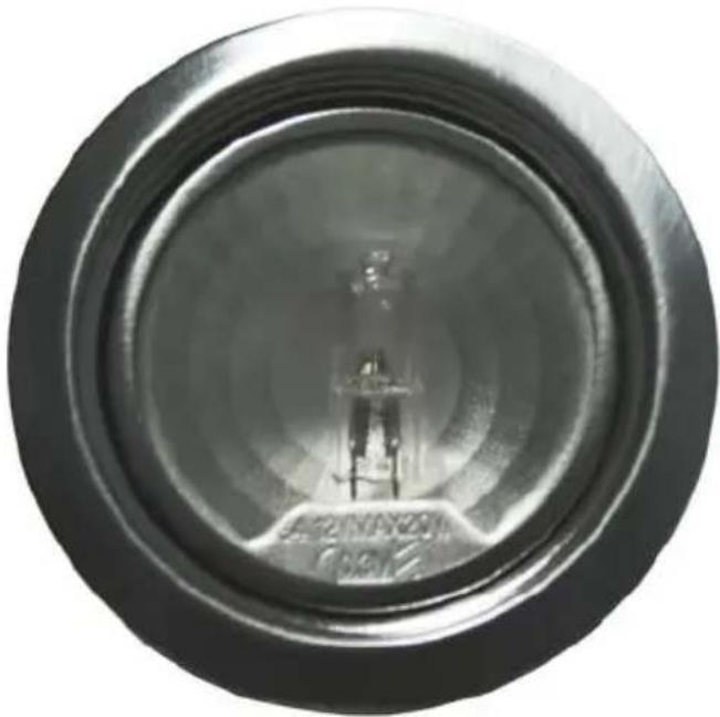
natural_image
Close-up of a circular mechanical component with concentric rings and a central shaft (no visible text or symbols)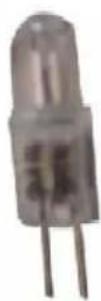
G4 12V 20W
natural_image
Circular ceramic dish with three dark handles and a light interior (no text or symbols visible)Composants Components Bauelemente
Componenti Componentes Onderdelen
natural_image
Line drawing of a four-legged metal frame structure with bolts and supports (no text or symbols)8
natural_image
Two identical white rectangular panels with black grout, shown side by side (no text or symbols)
natural_image
Simple line drawing of a rectangular box with a folded corner (no text or symbols)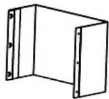
natural_image
Simple line drawing of a 3D rectangular frame with corner brackets (no text or symbols)
text_image
Rottin 版 10: Mio. 2007-05-03 版 11: 2007-05-04 版 12: 2007-05-05 版 13: 2007-05-06 版 14: 2007-05-07 版 15: 2007-05-08 版 16: 2007-05-09 版 17: 2007-05-10 版 18: 2007-05-11 版 19: 2007-05-12 版 20: 2007-05-13 版 21: 2007-05-14 版 22: 2007-05-15 版 23: 2007-05-16 版 24: 2007-05-17 版 25: 2007-05-18 版 26: 2007-05-19 版 27: 2007-05-20 版 28: 2007-05-21 版 29: 2007-05-22 版 30: 2007-05-23 版 31: 2007-05-24 版 32: 2007-05-25 版 33: 2007-05-26 版 34: 2007-05-27 版 35: 2007-05-28 版 36: 2007-05-29 版 37: 2007-05-30 版 38: 2007-05-31 版 39: 2007-05-32 版 40: 2007-05-33 版 41: 2007-05-34 版 42: 2007-05-35 版 43: 2007-05-36 版 44: 2007-05-37 版 45: 2007-05-38 版 46: 2007-05-39 版 47: 2007-05-40 版 48: 2007-05-41 版 49: 2007-05-42 版 50: 2007-05-43 版 51: 2007-05-44 版 52: 2007-05-45 版 53: 2007-05-46 版 54: 2007-05-47 版 55: 2007-05-48 版 56: 2007-05-49 版 57: 2007-05-50 版 58: 2007-05-51 版 59: 2007-05-52 版 60: 2007-05-53 版 61: 2007-05-54 版 62: 2007-05-55 版 63: 2007-05-56 版 64: 2007-05-57 版 65: 2007-05-58 版 66: 2007-05-59 版 67: 2007-05-60 版 68: 2007-05-61 版 69: 2007-05-62 版 70: 2007-05-63 版 71: 2007-05-64 版 72: 2007-05-65 版 73: 2007-05-66 版 74: 2007-05-67 版 75: 2007-05-68 版 76: 2007-05-69 版 77: 2007-05-70 版 78: 2007-05-71 版 79: 2007-05-72 版 80: 2007-05-73 版 81: 2007-05-74 版 82: 2007-05-75 版 83: 2007-05-76 版 84: 2007-05-77 版 85: 2007-05-78 版 86: 2007-05-79 版 87: 2007-05-80 版 88: 2011/1/1/1/1/1/1/1/1/1/1/1/1/1/1/1/1/1/1/1/1/1/1/1/1/1/1/1/1/1/1/1/1/1/1/1/1/1/1/1/1/1/1/1/1/1/1/1/1/1/1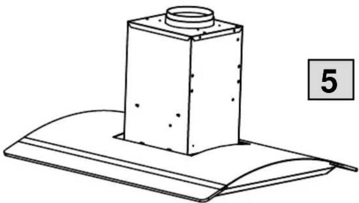
natural_image
Line drawing of a mechanical component with a cylindrical top and curved base, labeled with number 5 (no text or symbols on the object itself)Plaque Signalétique de la hotte Rating plate of the cookerhood Typenschild im Inneren der Dunstesse Etichetta all'interno della cappa Etiqueta de la campana Typeplaatje van de afzuigkap
natural_image
Diagram showing a device being processed into a device with a downward arrow indicating process (no text or symbols present)Modèle
Model
Modell
Modello
Modelo
Model
Numéro de série
Serial number
Seriennummer
Numero di serie
Numero de serie
Serienummer
Roblin
Made in France
CODE: 6031200
MOD: ESPRIT/2 C 900 EE IX/V
220-240V\~50Hz
220V\~60Hz


1×275W
4x20W
TOT. 355W

Roblin
FRANKE France S.A.S.