
Open 610 Escamotable - Basket ROBLIN - Free user manual and instructions
Find the device manual for free Open 610 Escamotable ROBLIN in PDF.
| Product type | Integrated retractable hood |
| Brand | Roblin |
| Model | Open 610 Retractable |
| Width | 598 mm |
| Depth (adjustable) | 270 to 360 mm |
| Height | 350 mm |
| Power supply | 230 V - 50 Hz |
| Total power | 350 W |
| Motor power | 2 x 135 W |
| Lighting | 2 x 40 W (halogen bulbs) |
| Number of speeds | 3 |
| Exhaust nozzle diameter | 100 mm or 120 mm |
| Main functions | Extraction, external evacuation or recirculation, integrated lighting |
| Grease filter | Dishwasher safe, replace every 2 months |
| Activated carbon filter (recirculation) | Replace approximately 2 times a year (ref. kit AH 4020 F1) |
| Body maintenance | Warm water and non-aggressive detergent, avoid abrasive products |
| Safety | Switch cutting power when canopy closes, omnipolar switch recommended |
| Installation | Wall mounting with support brackets, depth adjustment, fixing to adjacent cabinets |
| Minimum installation height | 650 mm between hood and hob |
| Weight | Approximately 15 kg (not specified) |
| Standards | CE, directives 76/889, 82/499, 73/23, 89/336, 93/68 |
Frequently Asked Questions - Open 610 Escamotable ROBLIN
User questions about Open 610 Escamotable ROBLIN
0 question about this device. Answer the ones you know or ask your own.
Ask a new question about this device
Download the instructions for your Basket in PDF format for free! Find your manual Open 610 Escamotable - ROBLIN and take your electronic device back in hand. On this page are published all the documents necessary for the use of your device. Open 610 Escamotable by ROBLIN.
USER MANUAL Open 610 Escamotable ROBLIN
natural_image
Line drawing of a 3D architectural structure with a sloped roof and rectangular base (no text or symbols)Open 610
Instructions Booklet Mode d'emploi Bedienungsanleitung Gebruiksaanwijzing
FOR THE USER 4
DEFINITION 4
Important Recommendations .... 4
USAGE 5
MAINTENANCE....5
FOR THE INSTALLER 6
INSTALLATION 6
EVACUATION DIRECTLY OUTDOORS 8
EVACUATION BY RECYCLING 9
ELECTRICAL CONNECTION 10
DIRECTE AFVOER NAAR BUITEN 30
AFVOER BIJ CIRCULATIEKAP 30
ELECTRISCHE AANSLUITING 31
FOR THE USER
Now that your cooker hood has been installed in accordance with the “For the Fitter” part of these instructions by an authorized specialist, please read the following pages carefully. This will help you to become familiar with and to make the best use of the features of your appliance.
DEFINITION
- These appliance are extendable hoods designed to be installed in the place of a tall 60 cm wide kitchen unit.
- They can be adapted to all units in which the body depth (excluding the door) is between 270 mm and 360 mm and with a minimum height of 350 mm.
- The hood draws in cooking vapors and evacuates them to the outdoors (evacuation version) or returns them into the kitchen after passing through an active carbon filter in which they are purified (“recycling” version).
- A front panel is fixed to the hood auvent for aesthetic continuity of the upper kitchen units.
- Important: on delivery, the hood is equipped to operate in the "outdoors evacuation" version.
- For use in the recycling version, install the active carbon kit reference AH 4020 F1 that you can order from your Fitter.
Important Recommendations
- In a kitchen heated with an appliance connected to a chimney (for example stove, cooker, etc.), install the “recycling” version of the hood and check that there is adequate room ventilation (fresh air).
- Preferably use the cooking areas at the back of your appliance.
- Operate the hood for a few minutes before starting cooking.
- Use low speed for simmering and dishes which produce little steam. (This speed can also be used to ventilate the kitchen).
- Use the high extraction speed for normal use.
- When producing large quantities of steam during cooking, use the high extraction speed and keep the hood operating after finishing cooking (about 15 or 30 minutes).
- Do not connect the hood to smoke or extraction ducts already being used.
- Check that the mains voltage is the same as the values stated on the identification plate inside the hood.
- Do not flambé food underneath the hood (the flames drawn in could damage the filters or create a fire risk).
- Deep frying equipment under the appliance must be constantly monitored.
- Regularly clean the grease filters.
For your safety, and to respect our guarantee conditions:
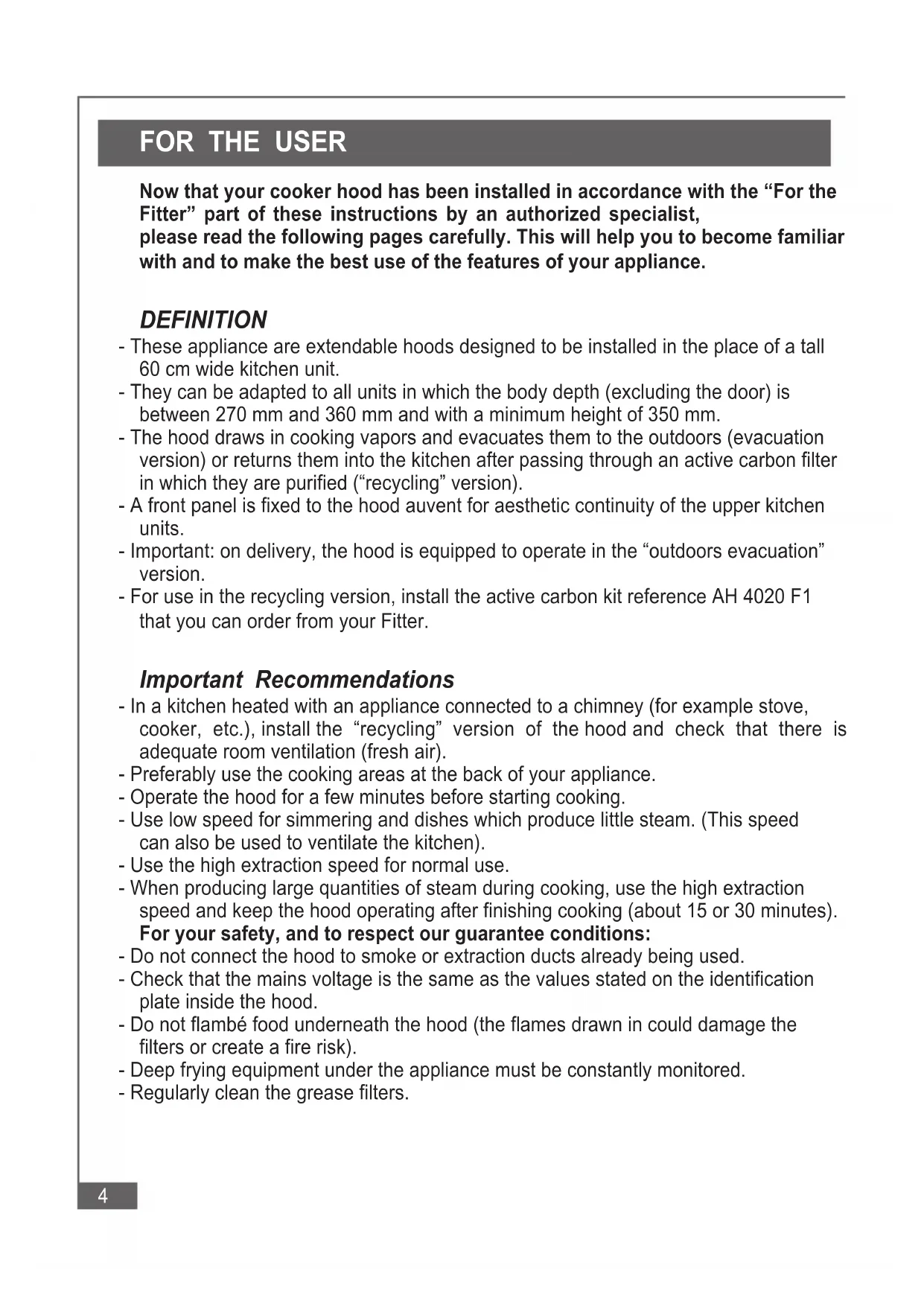
USAGE
The hood is fitted with a control box behind the opening, containing 3 controlside (fig.1).
- Slide "L" is used to switch the lighting on and off.
- Slide "M" is used to start or stop the fan, confirmed by a power on indicator.
- Slide "V" is used to select the extraction power from "1" to "3".
A contactor above the control box cuts off the power as soon as the auvent is fully closed, but functions previously regulated with the slides are maintained.
MAINTENANCE
Before carrying out any work (cleaning - changing filters - lighting), switch the appliance off by pulling the plug out if you can reach it, or by switching the circuit breaker off.
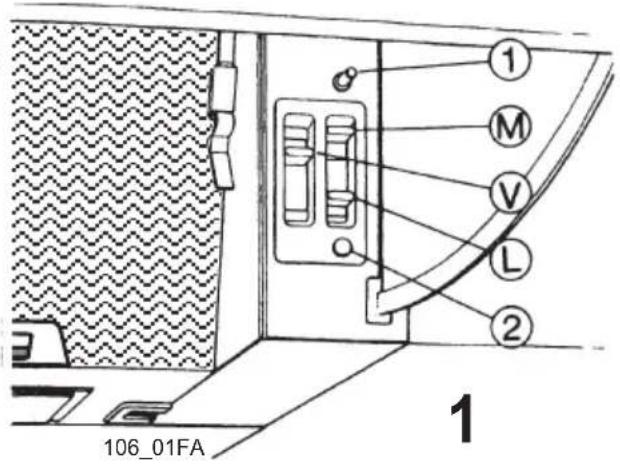
Grease filter
The metal grease filter should be cleaned every two months with normal usage and can be cleaned in a dishwasher or by hand using a mild detergent or liquid soap.
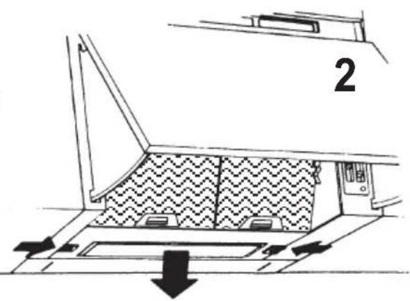
Proceed as follows: (see fig.2 - fig.3)
- Open the auvent to the end stop.
- Remove the filters one at a time, pushing the handle towards the rear of the hood.
When replacing, ensure that the handle faces outwards.
NOTE: new grease filters can be obtained from your dealer.
Active carbon filters
(on appliance used in recycling version).
- Air drawn in also passes through the active carbon filter designed to eliminate cooking odors.
- This filter cannot be cleaned, and therefore must be replaced at a frequency which depends on the frequency of use (about twice per year).
- Each filter is supplied with installation instructions.
Panelwork
Use lukewarm water only, to which a non-aggressive cleaning liquid is added. Do not use abrasive or aggressive products, or products containing alcohol.
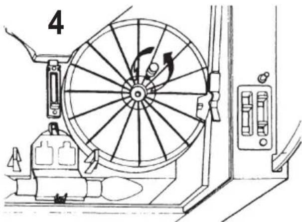
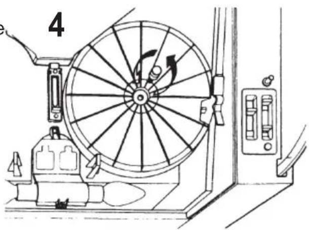
Lighting
- Lighting is provided by two 40 W bulbs.
- To replace them, remove the grease filters as described in the "Grease filter" section (fig. 4) to gain access to the bulbs.
- Replace the defective bulb or bulbs with identical models and replace the grease filters.
natural_image
Technical line drawing of a wheel assembly with directional arrows and components (no text or symbols)In case of problems
If you request assistance from your After Sales Service, you should inform them of the characteristics stated on the identification plate close to the motor in your hood (model - type - serial number).
FOR THE INSTALLER
As the specialist, only you are competent to install and connect appliances.
This is why our guarantee is applicable exclusively and solely to appliances which have been installed and connected by yourself, in accordance with the requirements of ordinances in force. You will be responsible if this condition is not respected.
INSTALLATION
- The hood must always be fitted above the center of the cooker hob.
- The minimum distance between the top of the cooker hob and the bottom of the hood shall be 650 mm.
- If your cooking appliance has a cover, check that it can be lifted without hindrance.
Assembly
- All accessories necessary for installation are supplied with the appliance.
- Use the template to position the support lug wall attachment holes and drill the holes for the plugs (top edge of the hood aligned with the top of adjacent furniture).
- Attach the support lugs with appropriate screws.
Hood preparation
- Before starting wall mounting, the depth of the hood has to be adjusted to match the depth of adjacent furniture.
- The hood depth can be adjusted between 27 and 36 cm.
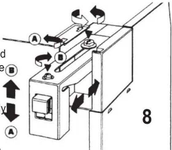
Depth adjustment:
1 - Measure the body depth of the furniture between which the hood is to be installed.
2 - Loosen the hexagonal bolts for the adjustment of the upper suspension hooks (fig. 8), pull the hooks to the correct dimension and retighten the bolts.
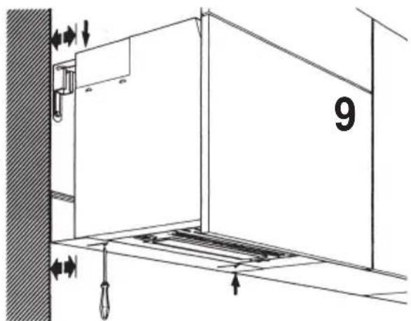
3 - Loosen the lower spacer plate support bolts (fig. 9), pull it to the right dimension and retighten the bolts. This square spacer plate with built in unequal ribs can be reversed depending on the required depth.
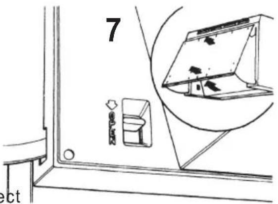
Auvent preparation
- This hood must be fitted with a facade similar to that for the furniture in the kitchen and fixed to the auvent (facade supplied by the furniture installer).
1 - Fully open the auvent and press the locking key at the front left inside (fig. 7) to completely remove theauvent.
2 - Drill the starter holes inside the facade using the drilling template provided for this purpose.
3 - Place the auvent on the panel aligning the holes and screw in using provided. Do not put it back on the hood before installation on the wall.
Wall mounting
- Attach the hood by its suspension hooks to the support lugs attached to the wall.
- To prevent accidental separation, drill and attach the two safety brackets (supplied with the appliance) to the wall so that they bear on the suspension hooks.
- If necessary, adjust the alignment with the adjacent furniture using the suspension hook adjustment bolts (fig. 8).
Additional attachment to adjacent furniture
- Remove the filter support grillage and use the holes visible in the side walls to attach to adjacent furniture. (The template supplied can be used before wall mounting).
Installing the evacuation duct
- Depending on the choice of evacuation ducts, install the 100 or 120 mm ∅ duct which attaches to the rear box by a bayonet system.
Connection
There is an adjustment lever inside the hood (fig. 4) for selecting "evacuation" or "recycling" (accessible after removing the grease filters).
- Lever down - recycling (air outlet by front upper louvers).
- Lever up - evacuation (outlet through rear duct). These positions must be respected in accordance with the selected use.
natural_image
Technical line drawing of a wheel assembly with rotating components and directional arrows (no text or symbols)Connection to an individual or collective duct
- Connect the hood to an individual or collective duct (unused flue) using pipes and connection pieces made of uninflammable material.
- When the evacuation version hood is used, it must not hinder existing ventilation or extraction, and must be in accordance with Unified Technical Document DTU n° 61-1.
- Connection fittings must be made in accordance with standard practice and respect safety conditions, and under no circumstances shall the evacuation duct discharge into the attic.
- Flues used as smoke ducts shall not be used.
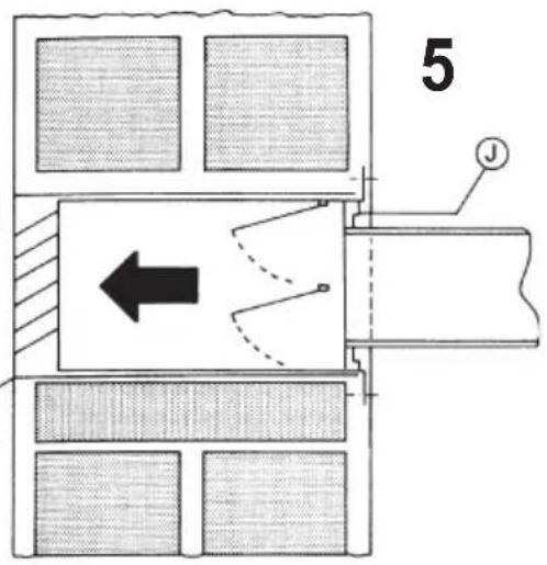
EVACUATION DIRECTLY OUTDOORS
- In this case, it is recommended that the telescopic suction cup reference AH 4009 F1 with built in non-return valve be used (fig. 5).
- This square suction cup was specially designed for hoods and can be built into any outside wall between 23 and 43 cm thick.
- Outside shutters prevent wind and rain from entering and a raised edge (water spray) on the lower edge prevents dirtying the facade.
- The built in non-return valve prevents return of cold air into the kitchen during winter.
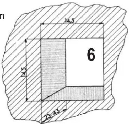
For wall drilling, see (fig. 6)
Special instructions provided with the suction cup give all necessary additional information.
EVACUATION BY RECYCLING
- Put the adjustment lever to the recycling position (down) and after installing the active carbon filter (as described in the installation part of these instructions and in accordance with the instructions attached to the recycling kit) the recycled air is discharged through the louvers at the top of the hood facade.
- In this case the hood must be drawn fully down to completely free the facade louvers. Replacement of the auvent (panel and facade assembled)
- Lift the auvent by its lower part and insert the two upper guide-slides in their respective housings.
- Pivot the auvent downwards inserting the two lower guide-slides and tilt the auvent until it closes.
- Reopen the auvent to make sure that it operates correctly and to check the presence of the stop at full opening.
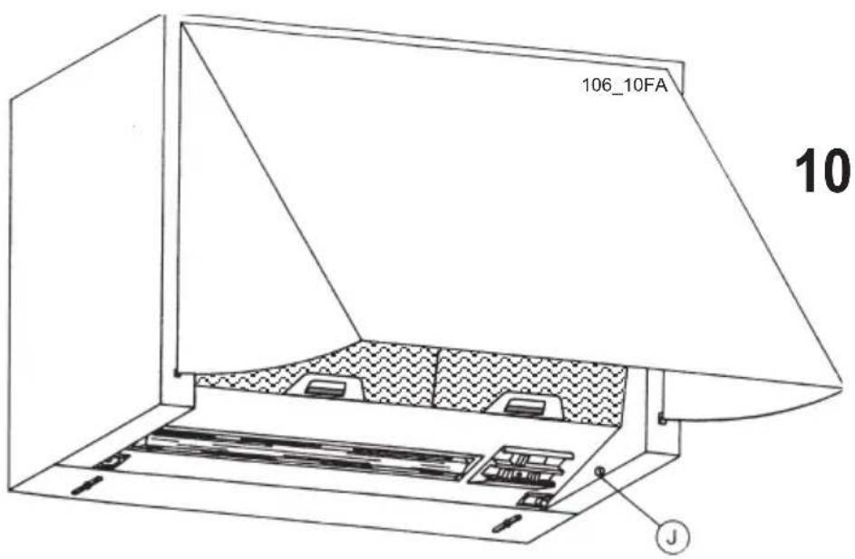
- Depending on the weight of the facade, the friction resistance of the auvent may be adjusted from the inside by means of screws located at the front corners of the appliance (fig. 10).
- If necessary, make a final alignment with the adjacent furniture by adjusting the auvent screws supporting the facade.
ELECTRICAL CONNECTION
- Connect the appliance cord to a 10/16 A standard grounded power outlet (2 pins + earthing pin), preferably located above the hood.
- If the power outlet is not permanently accessible, a 3-pole switch will have to be provided in the installation with a minimum contact opening of 3 mm.
- The installation shall comply with standard NF C 15.100.
| TECHNICAL DATA | |
| Power supply voltage 230 V - 50 HzTotal connection power 350 WMotor 2 x 135 WLighting 2 x 40 WNumber of speeds 3Evacuation duct diameter 100 or 120 mmHood width 598 mmHood depth 270/360 mmHood height 350 mm | |
| This hood complies with EEC directives 76.889 and 82.499 related toradioelectric disturbances (ordinance dated August 19th 1985 published inOfficial journal date September 1st 1985) | |
POUR L'UTILISATEUR
ENTRETIEN
natural_image
Technical line drawing of a mechanical device with a wheel and control panel (no text or symbols)En cas de panne
natural_image
Technical line drawing of a wheel assembly with labeled components (no text or symbols present)EVACUATION DIRECTE VERS
L'EXTÉRIEUR
This appliance complies with European regulations on low voltages, EEC Directive 73/23 on electrical safety, and with the following European regulations: EEC Directive 89/336 on electromagnetic compatibility and EEC Directive 93/68 on EC marking.