
PRSA900 - AV receiver PIONEER - Free user manual and instructions
Find the device manual for free PRSA900 PIONEER in PDF.
| Product Type | Audio Amplifier |
| Brand | Pioneer |
| Model | PRSA900 |
| Dimensions (W x H x D) | 282 mm x 65 mm x 371 mm |
| Weight (without cables) | 6.4 kg |
| Supply voltage | 14.4 V DC (10.8 V to 15.1 V) |
| Current consumption (max) | 28 A |
| Average current consumption | 9 A (4 channels) / 12 A (2 channels) |
| Fuse | 25 A x 2 |
| Maximum output power | 100 W x 4 (4 Ω) / 200 W x 2 (4 Ω) |
| Continuous output power | 50 W x 4 (14.4 V, 4 Ω, 0.08 % THD) / 100 W x 2 (14.4 V, 4 Ω, 0.8 % THD) |
| Load impedance | 4 Ω (2 Ω to 8 Ω permissible); bridged connection: 4 Ω to 8 Ω |
| Frequency response | 10 Hz to 100 kHz (+0 dB, -1 dB) |
| Signal-to-noise ratio | 108 dB (IEC-A) |
| Total harmonic distortion | 0.003 % (10 W, 1 kHz) |
| Channel separation | 75 dB (100 Hz to 10 kHz) |
| Slew rate | 70 V/μs |
| Damping factor | 100 |
| Gain adjustment range | 400 mV to 6.5 V |
| Maximum input level (RCA) | 6.5 V / 22 kΩ |
| Operating modes | 2 channels, 3 channels, 4 channels |
| Special functions | BFC (beat frequency control), protection circuit, power indicator |
| Inputs | 2 Cinch (RCA) jacks |
| Speaker outputs | Screw terminals (12 to 18 AWG) |
Frequently Asked Questions - PRSA900 PIONEER
User questions about PRSA900 PIONEER
0 question about this device. Answer the ones you know or ask your own.
Ask a new question about this device
Download the instructions for your AV receiver in PDF format for free! Find your manual PRSA900 - PIONEER and take your electronic device back in hand. On this page are published all the documents necessary for the use of your device. PRSA900 by PIONEER.
USER MANUAL PRSA900 PIONEER
Before Using This Product 1
Visit our website 1
In case of trouble 2
CAUTION 2
CAUTION 2
WARNING 2
Setting the Unit 3
Terminal Cover 4
Badge 4
BFC (Beat Frequency Control) Switch 4
Power Indicator 4
Input Select Switch 4
Gain Control 4
Setting the Gain properly 5
Connecting the Unit 6
Connection Diagram 7
Solderless Terminal Connections 8
Connecting the Speaker Output Terminals .... 8
Connecting the Speakers and Input Wires 9
Connecting the Power Terminal 11
Installation 12
Example of installation on the floor mat or on the chassis 13
Replacing the terminal cover 13
Changing the Direction of the Badge 13
Specifications 14
oduct
Thank you for purchasing this PIONEER product. Before attempting operation, be sure to read this manual.

If you want to dispose this product, do not mix it with general household waste. There is a separate collection system for used electronic products in accordance with legislation that requires proper treatment, recovery and recycling.
Private households in the member states of the EU, in Switzerland and Norway may return their used electronic products free of charge to designated collection facilities or to a retailer (if you purchase a similar new one).
For countries not mentioned above, please contact your local authorities for the correct method of disposal.
By doing so you will ensure that your disposed product undergoes the necessary treatment, recovery and recycling and thus prevent potential negative effects on the environment and human health.
Visit our website
Visit us at the following site: http://www.pioneer.co.uk
- Register your product. We will keep the details of your purchase on file to help you refer to this information in the event of an insurance claim such as loss or theft.
We offer the latest information about Pioneer Corporation on our website.
In case of trouble
When the unit does not operate properly, contact your dealer or the nearest authorized PIONEER Service Station.

CAUTION
- Never replace the fuse with one of greater value or rating than the original fuse. Use of an improper fuse could result in overheating and smoke and could cause damage to the product and injury including burns.
- Use the supplied hexagonal wrench to tighten screws when fastening wires to the terminal or when changing the direction of the badge. The use of a long, commercially available hexagonal wrench can cause excessive torque to be applied possibly resulting in damage to terminals and wires.

CAUTION
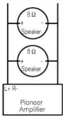
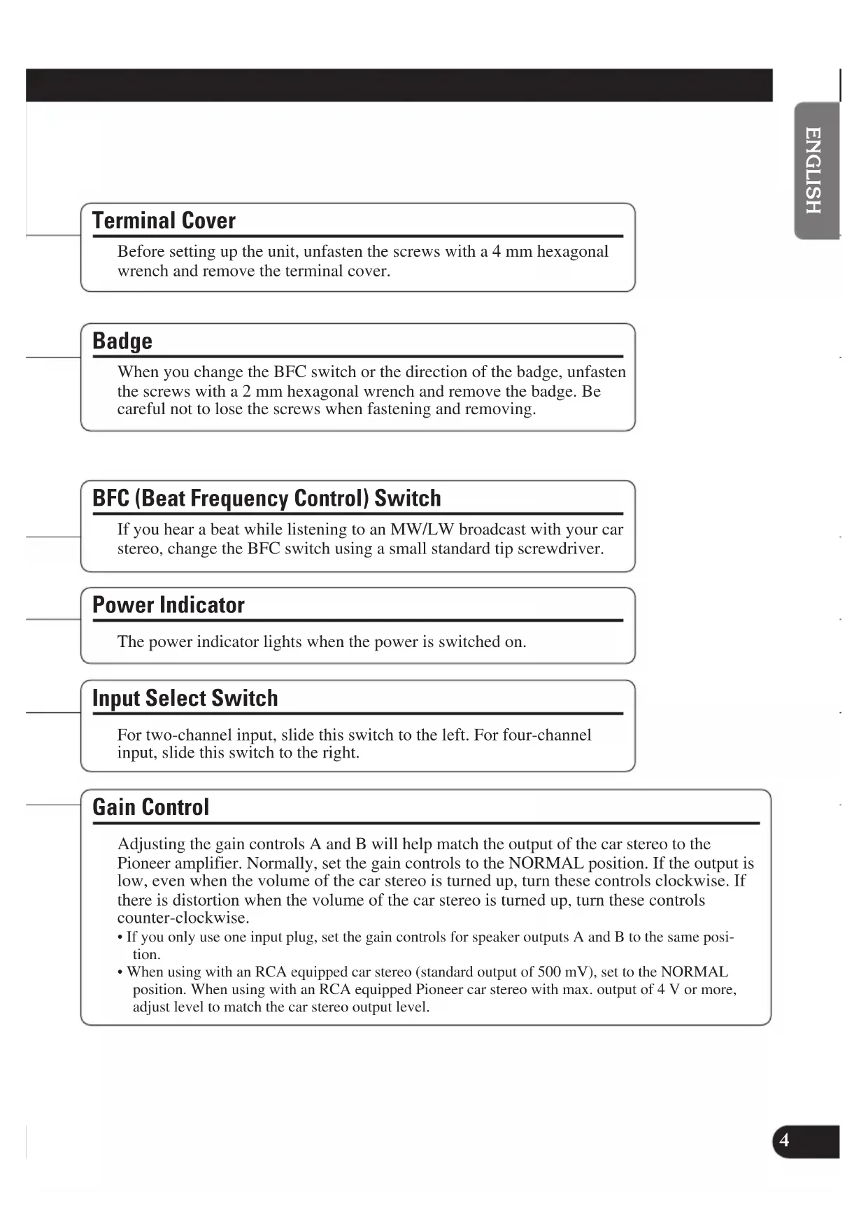
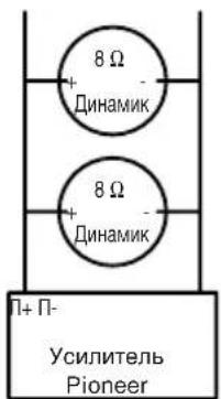
Diagram A - Proper
4Ω Bridged Mode
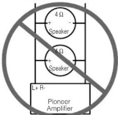
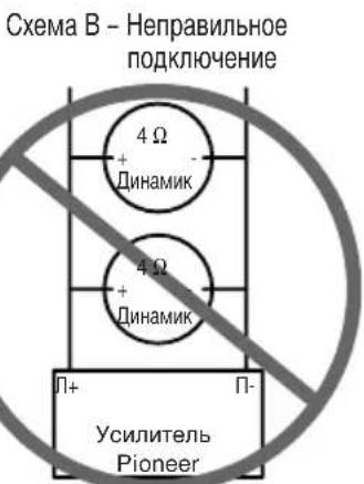
Diagram B - Improper
2Ω Bridged Mode
DO NOT install or use your Pioneer amplifier by wiring speakers rated at 4 (or lower) in parallel to achieve a 2 (or lower) bridged mode (Diagram B). Amplifier damage, smoke, and overheating could result from improper bridging. The amplifier surface could also become hot to the touch and minor burns could result.
To properly install or use a bridged mode for a two-channel amplifier and achieve a 4 load, wire two 8 speakers in parallel with Left + and Right - (Diagram A) or use a single 4 speaker. For a four-channel amplifier, follow the speaker output connection diagram for bridging as shown
on the back of your amplifier, and wire two 8 Ωspeakers in parallel to achieve a 4 Ωload or use a single 4 Ωspeaker per channel.
If you have any questions or concerns, please contact your local authorized Pioneer dealer or call Pioneer customer service.
WARNING
- We recommended that you use the special red battery and ground wire [RD-228], which is sold separately. Connect the battery wire directly to the car battery positive terminal (+) and the ground wire to the car body.
- Do not touch the amplifier with wet hands. Otherwise you may get an electric shock. Also, do not touch the amplifier when it is wet.
- For traffic safety and to maintain safe driving conditions, keep the volume low enough so that you can still hear normal traffic sound.
- Check the connections of the power supply and speakers if the fuse of the separately sold battery wire or the amplifier fuse blows. Detect the cause and solve the problem, then replace the fuse with another one of the same size and rating.
- To prevent malfunction of the amplifier and speakers, the protective circuit will cut the power supply to the amplifier (sound will stop) when an abnormal condition occurs. In such a case, switch the power to the system OFF and check the connection of the power supply and speakers. Detect the cause and solve the problem.
- Contact the dealer if you cannot detect the cause.
- To prevent an electric shock or short-circuit during connection and installation, be sure to disconnect the negative (-) terminal of the battery beforehand.
- Confirm that no parts are behind the panel when drilling a hole for installation of the amplifier. Be sure to protect all cables and important equipment such as fuel lines, brake lines and the electrical wiring from damage.
- DO NOT allow amplifier to come into contact with liquids due to, for example, the location where the amplifier is installed. Electrical shock could result. Also, amplifier and speaker damage, smoke, and overheating could result from contact with liquids. In addition, the amplifier surface and the surface of any attached speakers could become hot to the touch and minor burns could result.

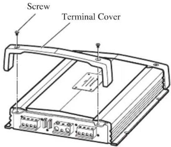
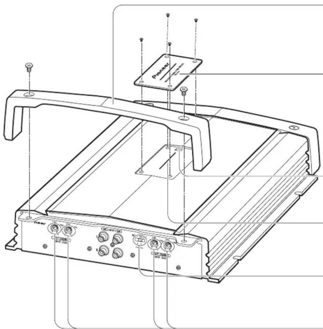
Terminal Cover
Before setting up the unit, unfasten the screws with a 4mm hexagonal wrench and remove the terminal cover.
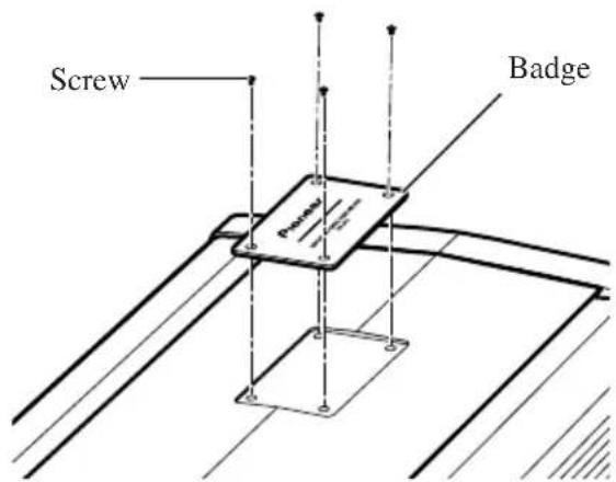
Badge
When you change the BFC switch or the direction of the badge, unfasten the screws with a 2mm hexagonal wrench and remove the badge. Be careful not to lose the screws when fastening and removing.
BFC (Beat Frequency Control) Switch
If you hear a beat while listening to an MW/LW broadcast with your car stereo, change the BFC switch using a small standard tip screwdriver.
Power Indicator
The power indicator lights when the power is switched on.
Input Select Switch
For two-channel input, slide this switch to the left. For four-channel input, slide this switch to the right.
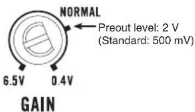
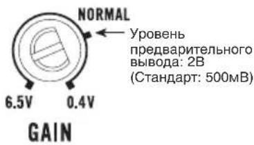
Gain Control
Adjusting the gain controls A and B will help match the output of the car stereo to the Pioneer amplifier. Normally, set the gain controls to the NORMAL position. If the output is low, even when the volume of the car stereo is turned up, turn these controls clockwise. If there is distortion when the volume of the car stereo is turned up, turn these controls counter-clockwise.
- If you only use one input plug, set the gain controls for speaker outputs A and B to the same position.
- When using with an RCA equipped car stereo (standard output of 500mV ), set to the NORMAL position. When using with an RCA equipped Pioneer car stereo with max. output of 4V or more, adjust level to match the car stereo output level.
Setting the Gain properly
- This unit is equipped with a protective function to prevent malfunction of the unit itself and speakers from too much output, improper use or improper connection.
- When outputting sound at high volume etc., this function will cut off the sound output in a few seconds. But this is not a malfunction. When you turn down the volume of the head unit the sound output will be restored.
- If sound output is cut, the gain control of this unit may be improperly set. To ensure continuous sound output at increased volume of the head unit, set the gain control of the amplifier to a proper position according to the preout maximum output level of the head unit.
Gain Control of This Unit
There is no need to decrease the volume of the head unit and too much output is controlled.
Relationship between the gain of the amplifier and the output power of the head unit
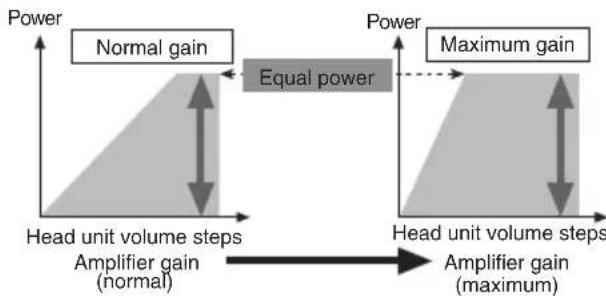
- If you raise the gain of the amplifier to an improper level, only distortion is increased and the power increases only slightly.
Signal waveform when outputting at high volume by the gain control of the amplifier
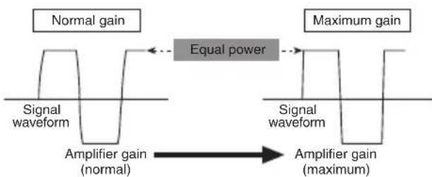
- With high output the signal waveform is distorted, if you raise the gain of the amplifier the power changes only slightly.
- If you decrease the volume of the head unit and set the gain control of the amplifier to the proper position but still the sound cuts out from time to time, contact the nearest authorized PIONEER Service Station.

CAUTION
- Disconnect the negative (-) terminal of the battery to avoid the risk of short-circuit and damage to the unit.
- Secure the wiring with cable clamps or adhesive tape. To protect the wiring, wrap adhesive tape around it where they lie against metal parts.
-
Do not route wires where they will get hot, for example where the heater will blow over them. If the insulation heats up, it may become damaged, resulting in a short-circuit through the vehicle body.
-
Make sure that wires will not interfere with moving parts of the vehicle, such as the gearshift, handbrake or seat sliding mechanism.
- Do not shorten any wires. Otherwise the protection circuit may fail to work when it should.
- Never feed power to other equipment by cutting the insulation of the power supply wire to tap from the wire. The current capacity of the wire will be exceeded, causing overheating.
- Never replace the fuse with one of greater value or rating than the original fuse. Use of an improper fuse could result in overheating and smoke and could cause damage to the product and injury including burns.

CAUTION
To prevent damage and/or injury
- Do not ground the speaker wire directly or connect a negative (-) lead wire for several speakers.
- This unit is for vehicles with a 12-volt battery and negative grounding. Before installing it in a recreational vehicle, truck or bus, check the battery voltage.
- If the car stereo is kept on for a long time while the engine is at rest or idling, the battery may go dead. Turn the car stereo off when the engine is at rest or idling.
-
If the system remote control wire of the amplifier is connected to the power terminal through the ignition switch (12 V DC), the amplifier will always be on when the ignition is on—regardless of whether the car stereo is on or off. Because of this, the battery could go dead if the engine is at rest or idling.
-
Speakers to be connected to the amplifier should conform with the standards listed below. If they do not conform, they may catch fire, emit smoke or become damaged. The speaker impedance must be 2 ohms to 8 ohms. But in case of two-channel and other bridge connections, the speaker impedance must be 4 ohms to 8 ohms.
- Install and route the separately sold battery wire as far away as possible from the speaker wires. Install and route the separately sold battery wire, ground wire, speaker wires and the amplifier as far away as possible from the antenna, antenna cable and tuner.
- Cords for this product and those for other products may be different colors even if they have the same function. When connecting this product to another product, refer to the supplied manuals of both products and connect cords that have the same function.
Speaker Channel Speaker Type Power
| Four-channel | Subwoofer Nominal input: Min. 55 W |
| Other than subwoofer Max. input: Min. 100 W | |
| Two-channel | Subwoofer Nominal input: Min. 150 W |
| Other than subwoofer Max. input: Min. 200 W | |
| Three-channel Subwoofer Nominal input: Min. 55 W | |
| Speaker output A Other than subwoofer Max. input: Min. 100 W | |
| Three-channel Subwoofer Nominal input: Min. 150 W | |
| Speaker output B Other than subwoofer Max. input: Min. 200 W | |
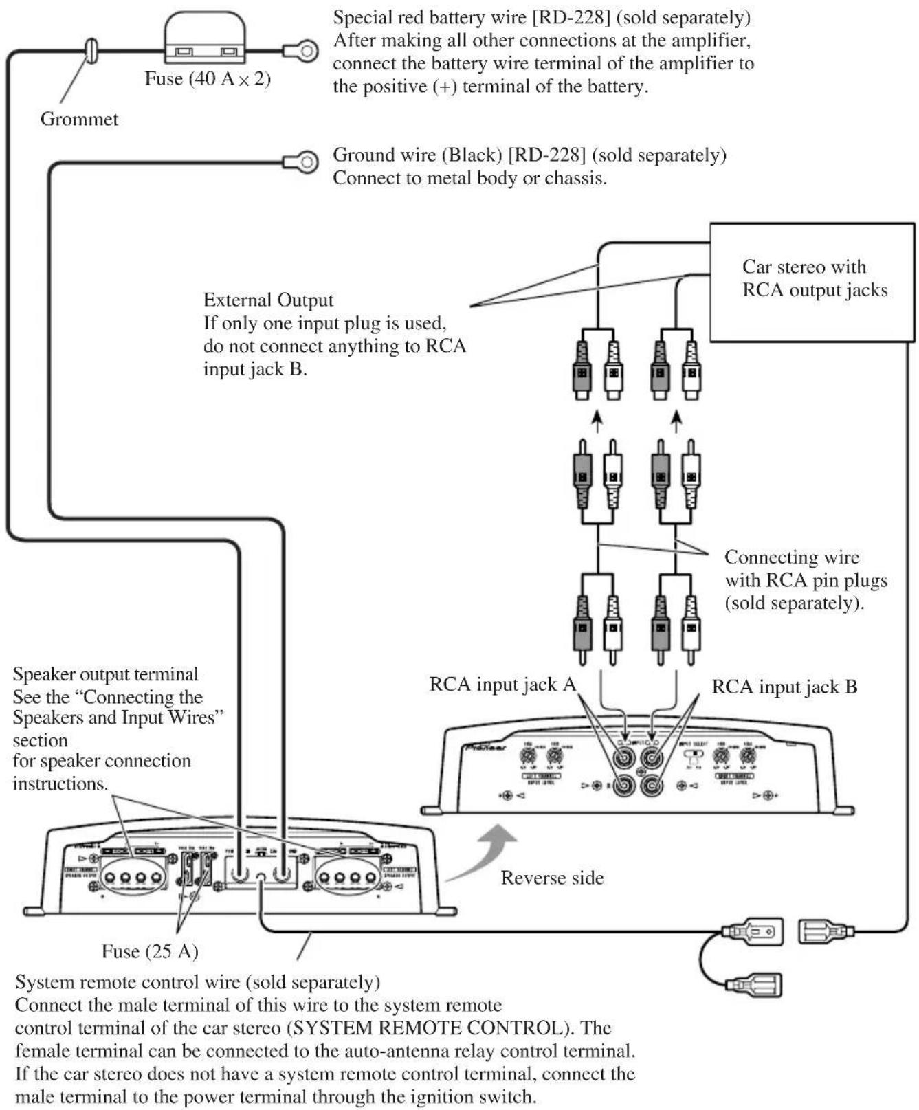
Connection Diagram
- This diagram shows connections using external output (subwoofer output). Slide the input switch to the left.
Solderless Terminal Connections
- Do not connect a cord having an exposed core wire to the power terminals of this amplifier (Power terminal, GND terminal, System remote control terminal). Disconnection or breakage of the core wire can cause a fire or short-circuit.
- Since the wire will become loose over time, it must be periodically inspected and tightened as necessary.
- Do not solder or bind the ends of the twisted wires.
- Fasten while making sure to not to clamp the insulating sheath of the wire.
- Use the supplied hexagonal wrench to tighten and loosen the terminal screw of the amplifier. Securely fasten the wire with the terminal screw. However, since excessively tightening the terminal screw of the System remote control has the risk of damaging the wire, be careful not to tighten excessively by observing the status of the wire when tightening.
Connecting the Speaker Output Terminals
Use a 12 AWG to 18 AWG wire for the speaker wire.
- Expose the end of the speaker wires using nippers or a cutter by about 14 mm to 16 mm.
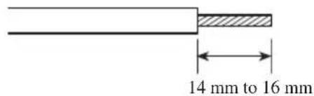
- Connect the speaker wires to the speaker output terminals.
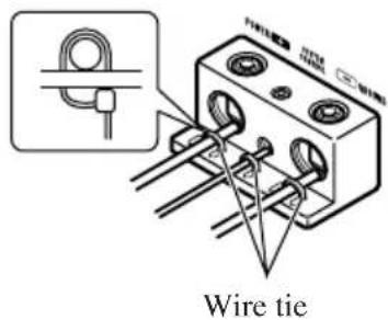
Fix the speaker wires securely with the terminal screws.
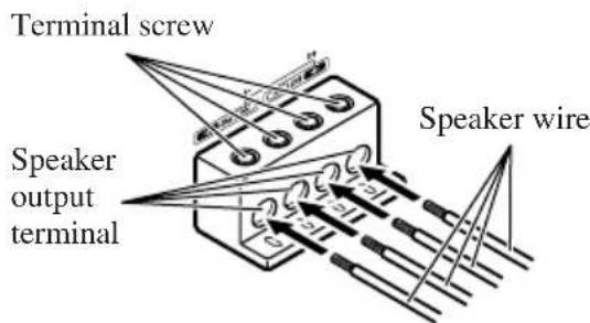
- Put the wire ties in the slits and wrap the wire ties around the wires.
Make sure the wires are connected and attached properly before wrapping the wires around the wires.
- Wrap the wire tie around the wire insulation, not the stripped wire.
- Cut off any excess portions of the wire ties.
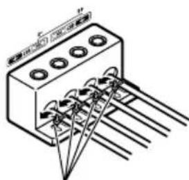
Wire tie
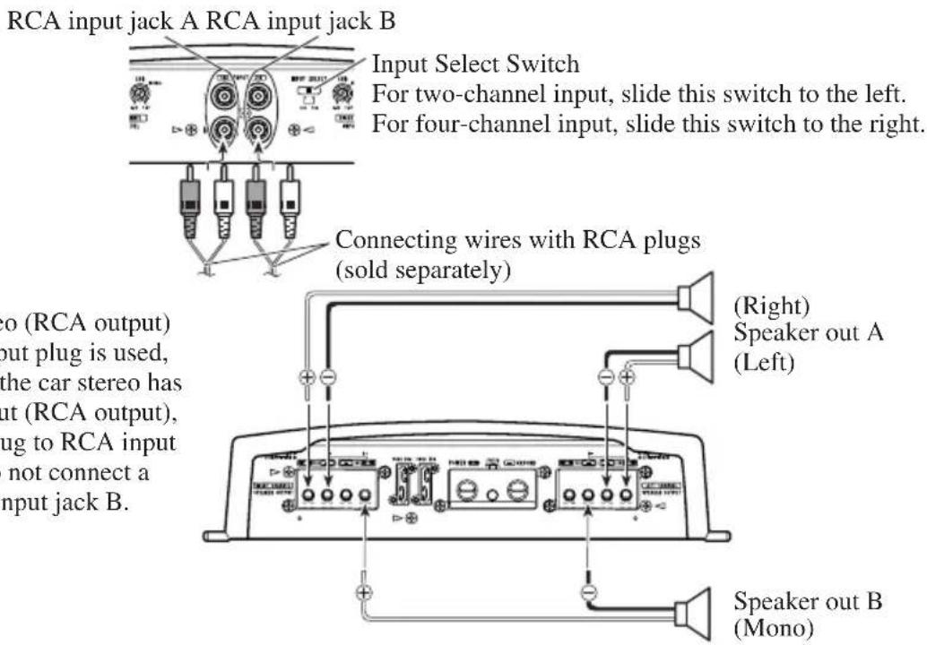
Connecting the Speakers and Input Wires
The speaker output mode can be four-channel, three-channel (stereo + mono) or two-channel (stereo, mono). Connect the speaker leads to suit the mode according to the figures shown below.
Four-channel mode
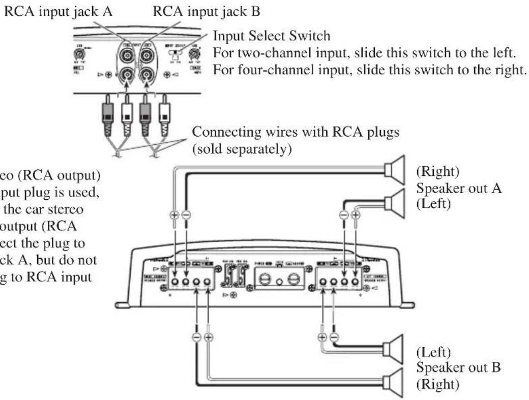
From car stereo (RCA output) If only one input plug is used, such as when the car stereo has only one output (RCA output), connect the plug to RCA input jack A, but do not connect a plug to RCA input jack B.
Three-channel mode
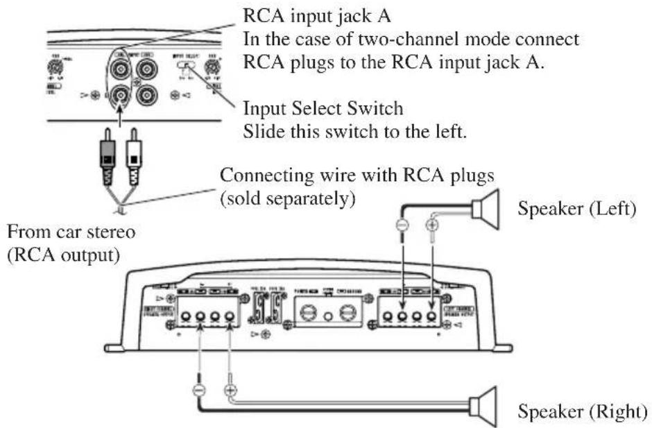
Two-channel mode (Stereo)
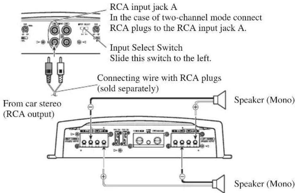
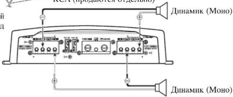
Two-channel mode (Mono)
Connecting the Power Terminal
- We recommended that you use the special red battery and ground wire [RD-228], which is sold separately. Connect the battery wire directly to the car battery positive terminal (+) and the ground wire to the car body.
- Recommended wires size (AWG: American Wire Gauge) is as follows. The battery wire and the ground wire must be same size.
- Use a 10 AWG to 20 AWG wire for the system remote control wire.
Battery Wire and Ground Wire Size
| Wire Length less than 3.6 m less than 6.4 m |
| Wire Size 8 AWG 6 AWG |
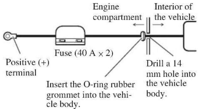
1. Pass the battery wire from the engine compartment to the interior of the vehicle.
After making all other connections to the amplifier, connect the battery wire terminal of the amplifier to the positive (+) terminal of the battery.
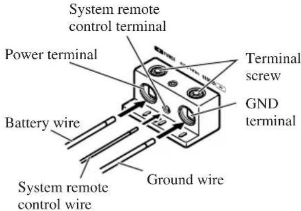
2. Connect the wires to the terminal.
Fix the wires securely with the terminal screws.
WARNING
Failure to securely fasten the battery wire to the terminal using the terminal screws could cause the terminal area to overheat and could result in damage and injury including minor burns.
3. Put the wire ties in the slits and wrap the wire ties around the wires.
Make sure the wires are connected and attached properly before wrapping the wires around the wires.
- Wrap the wire tie around the wire insulation, not the stripped wire.
- Cut off any excess portions of the wire ties.

CAUTION
- Do not install in:
Places where it could injure the driver or passengers if the vehicle stops suddenly.
Places where it may interfere with the driver, such as on the floor in front of the driver's seat. - Make sure that wires are not caught in the sliding mechanism of the seats, resulting in a short-circuit.
- Confirm that no parts are behind the panel when drilling a hole for installation of the amplifier. Protect all cables and important equipment such as fuel lines, brake lines and electrical wiring from damage.
- Install tapping screws in such a way that the screw tip does not touch any wire. This is important to prevent wires from being cut by vibration of the car, which can result in fire.
DO NOT allow amplifier to come into contact with liquids due to, for example, the location where the amplifier is installed. Electrical shock could result. Also, amplifier and speaker damage, smoke, and overheating could result from contact with liquids. In addition, the amplifier surface and the surface of any attached speakers could become hot to the touch and minor burns could result.
To ensure proper installation, use the supplied parts in the manner specified. If any parts other than the supplied ones are used, they may damage internal parts of the amplifier, or they may become loose causing the amplifier to shut down. - Never replace the fuse with one of greater value or rating than the original fuse. Use of an improper fuse could result in overheating and smoke and could cause damage to the product and injury including burns.

CAUTION
To prevent malfunction and/or injury
To ensure proper heat dissipation of the amplifier, be sure of the following during installation.
-Allow adequate space above the amplifier for proper ventilation.
-Do not cover the amplifier with a floor mat or carpet.
- DO NOT allow amplifier to come into contact with liquids due to, for example, the location where the amplifier is installed. Electrical shock could result. Also, amplifier and speaker damage, smoke, and overheating could result from contact with liquids. In addition, the amplifier surface and the surface of any attached speakers could become hot to the touch and minor burns could result.
- Do not install the amplifier on unstable places such as the spare tire board.
- The best location for installation differs with the car model and installation location. Secure the amplifier at a sufficiently rigid location.
- Make temporary connections first and check that the amplifier and the system operate properly.
After installing the amplifier, confirm that the spare tire, jack and tools can be easily removed.
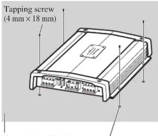
Example of installation on the floor mat or on the chassis
- Place the amplifier where it is to be installed. Insert the supplied tapping screws (4mm× 18mm) into the screw holes. Push on the screws with a screwdriver so they make marks where the installation holes are to be located.
- Drill 2.5mm diameter holes at the point marked, and install the amplifier, either on the carpet or directly to the chassis.
Floor mat or chassis
Drill a 2.5mm diameter hole
Replacing the terminal cover
- Align the unit and terminal cover, and insert the screw.
- Tighten the screw with a 4mm hexagonal wrench.
Changing the Direction of the Badge
- To remove the badge, loose screws by using a 2mm hexagonal wrench.
- Change the direction of badge, and then tighten the screws with a hexagonal wrench.
Specifications
Power source 14.4 V DC (10.8 V to 15.1 V allowable)
Grounding system Negative type
Current consumption 28 A (at continuous power, 4
Average current drawn* 9 A (4 Ω for four channels)
12 A (4 Ωfor two channels)
Fuse 25 A x 2
Dimensions 282 mm (W) × 65 mm (H) × 371 mm (D)
Weight 6.4 kg (Leads for wiring not included)
Maximum power output 100 W × 4 (4 Ω) / 200 W × 2 (4 Ω)
Continuous power output 50 W × 4 (at 14.4 V, 4 Ω, 20 Hz to 20 kHz 0.08% THD)
100W× 2 (at 14.4V,4 ,20Hz to 20kHz0.8% THD)
50W× 4 (at 14.4V,2 ,20Hz to 20kHz0.8% THD)
Load impedance 4Ω (2 Ω to 8 Ω allowable)
(Bridge connection: 4 to 8 allowable)
Frequency response 10 Hz to 100 kHz (+0 dB, -1 dB)
Signal-to-noise ratio 108 dB (IEC-A network)
Distortion 0.003% (10 W, 1 kHz)
Separation 75 dB (100 Hz to 10 kHz)
Slew rate. 70 V/μ sec.
Damping factor 100
Gain control 400 mV to 6.5 V
Maximum input level / impedance .RCA: 6.5 V / 22 kΩ
Note:
- Specifications and the design are subject to possible modification without notice due to improvements.
*Average current drawn
- The average current drawn is nearly the maximum current drawn by this unit when an audio signal is input. Use this value when working out total current drawn by multiple power amplifiers.
Bezoek onze website 1
Bij problemen 2
WAARSCHUWING 2
WAARSCHUWING 2
WAARSCHUWING 2
Slew rate. 70V / sec.
Dempingsfactor 100
Bo3BpaIIeHHe KpbIIIK Ha MeTo 13
H3MeHeHHe HanpaBJIeHHN 3M6JIeMBI 13
Cneunpkaa.. 14
BlaOaHbM Bac 3a IOKyIky DaHHoro yctpoiCTBaΦhPMBI PIONEER.IpeKJe yem Haatb KcIIyatauHIO daHHoro yctpoiCTBa,06aTeJbHO O3HaKOMbTEcb C HAcTOIHMMpyKOBOIDTBOM.

EcJIH Bbl JKeJiaTe yTHJINHINPOBaTb
daHHoe H3JeJIHe, He BblOpacbIbaiTe
eTO BMeCTe C O6bUHbIM 6bITOBbIM
MycopOM.CyIeCTByET OTDeJIbHa
CHCTema cOopa HCIOJIb3OBAHHbIX
3JIeKTPoHHbIX H3JeJIiB
COOTBeTCTBHN C 3aKOHOJaTeJIbCTBOM,
KOTOPa IIpeIIOJIaRaET
COOTBeTCTByIOJIee 6paJIeHHe,
BO3Bpat I NepepaBOTKy.
YacTHbIe KJIHeHTb I CtpaHax-ueHax EC, B IIIBeIaapn HOpBerHmOryT 6ecIIaTHo BO3BpAaTaH HcNoJIb3OBaHHbIe 3JIeKTKoHHbIe H3DeJIHn B COOTBeTCTByIOUHne IyHKTbI c6opa HJH dJIepy (Iprn IOKyInke cxOJHO HOBOrO H3JeJIH).
BctpaHax,HeIpeHnCJIeHHbIX BbIIIE,JIa IIOJyueHn HhΦOpMaunO npaBNbHbIX cnOCo6ax yTHJIN3aUNN ObaaTecb B COOTBeTCTByIOUne yUpeKDeHHa.
IocTyna TaKHM Opa3OM, BbMoKeTe 6bItb yBepehb IB TOM, YTO yTHJIN3HpyEmbI IpoDyKT oyJeT COOTBeTCTBYIOUHM Opa3OM 0baOToAH, IpeDaH B COOTBeTCTBYIOUHN IyHKT H IpepeaOToAH 6e3 BO3MOxHBIX HeRaTHBbIX IocJIeTcBnДЛЯ OKpyKaIOUeH cpebln 3IOpOBbjar IHOdeH.
Pocetnte haw caT
IocetHTe haHcaiT:
http://www.pioneer-rus.ru
3aperHCTppyIe npno6peTeHHoe H3JeJIHe.Mb coxpaHIM CBEJEHN O BaIIe NOKyIKe, YTO NMOKcET Bam cblIaTbcra Ha 3Ty HnOpMaHIO B cIyuae ctpaxOBOrO Tpe6oBaHHNo pnhHne nOtePH HIN KpaKn.
Camyo CBexyH HOpMaHIO Pioneer Corporation MOXHO IOJyHTb HA HAIICM Be6-caTe.
IeuctBnB Cnyae BO3HKnHOBeHn npo6nem
EcJH yctpoictBO He paobotaet JOJIKNbIM 6pa3OM, CBXHTcB C BAIIHM HJIePOM HIN 6JIHXaIIHcIyTBepKJDeHHO CTAHIIeH 06cLyKHBaHHI pOdyKHH PIO-NEER.

OCTOPOXHO!
Hikorda He 3aMeHnIte neperopeBHHn IpeoxpaHTeJIb IpeoxpAHHTeJEM C6bHIM HOMHaIOM. HcnoJIb3OBAHHe HenoXoJHrero IpeoxpAHHTeJ MoKeT pHBecTH K neperpeBy H BblJeJIeHHO Dbima. To TakKe MOKeT npHBecTH K NOBpeKdCHHO yCTPOHCTBa H TpaBMAM, B TOM HCJIe OJKOrAM.
IcnoJb3yIte NoCTaBJIeMbI IecTHyOJBHbI RaeyHbIKJIOU, YTO6b3aTAYb BHTbI, KOrJa coeHHReTe IpoBOJa cKJIeMMIIIMeHReTe HApBaJIeHHe 3MOJEMbI. HcIOJb3OBaHHe dINHHORo, cepHIHO bblNyckaemoroIIECTHYOJBHO raeHORo KJIIOHa MOKeT cTaTB IIpHnHHO IIpMHHeHHI Ype3MEPHORo BpaAioIeRO MOMHTa, BO3MOXHO IIpHBODIeRcKIOBpeKDeHHIO KJIeMM INIPOBOIOB.

OCTOPOXHO!
CxemaA- IpaBnIbHoe NOKJIoueHne
MocTOBoe coeINHeHne 4Ω
MocToboe coeINHeHne 2Ω
PnH yctAHOBKe HIN HCNOJIb3OBAHH BAIHEO yCHJHTeJI
Pioneer HE IIOIKJIHOAYTE INHAMIKN C HOMIHATOM 4Ω (HIN HHKE) npaJIIEJIbHO, YTObI NOyUHTB MOCTOBOE COeHHcNE 2Ω(HIN HIXe)(CxemaB).
HePaBHbHOE MOCTOBoe COeHHcNE MoKET pHBeCTH K NOBpeKdEHHO yCHJHTeJI, BblJeEHHO DbMa H nepePpeBy.
KpOME TORO, NOBepxHOCTb yCHJHTeJI MoKET HarPeTbC, H
IIpHKOCHOBHeK HeI MoXeT IIpHBecTH K He3HaHTeJIbHbIM OxOrAM.
IIOI OeCneueHn IpaBHLbHOYcTaHOBKN H HcNOJb3OBaHHM
MOCTOBORO COeINHeHHdByXKAHaJIbHOrO yCHITHe JN
IOCTHXeHHHARpy3Kn 4Ω,BblIOJTHHTpe NapaJIteJbHOe
coeINHeHHe8ΩINHAMKOB CJeBBIM+ H IpaBbIM-KaHaJIAMH
(CxemaA) HIN BOcIOJb3yHTecb OINHM 4ΩINHAMKOM. IPh
HCIOJb3OBaHHH YETbIPexKaHaJIbHOrO yCHHTeC JcElyET
BblIOJTHHT coeINHeHH B COOTBeTCTBHn CO CXeMOII
MOCTOBORO COeINHeHH, PInHBeEHHO Ha 3aDHe N aHeJH
BAIIero YcHJTTeJ, H NapaJIteJIbHO IOJKJIOOHHT bBa 8Ω
INHAMKa dJIb ObcEneHHH HArpy3Kn 4ΩHNIOIKJIOOHHTb
ODHH 4ΩINHAMK K KaXDMy KaHaIy.
EcIny BAC Bo3HNKHY T KaKHe-JINBOBPOCSb, CBXHTECb c
yIOJTHOMOeHHbIM INTEpOM φHPMb Pioneer HIN IO3BOHHTe B
OTJEIocNyXHBAHN NOkynateJei φHPMb Pioneer.
PPEyPExKDEHNE
MbpeKomeHnyeM,HTo6bBi HcnoJIb3OBAJH CnEHaJIbHbIe KpaCHbIe IpoBOJa [RD-228]J18 6aTapeH H3a3eMJIeHH, KOtOpBle IpoDAHOrCTOJeBHO. IIOCoEOHNHTe 3JEKTpHueckHII IPOBOJ 6aTapeH K IOJOXHTeJIbHOH KJIeMMe (+) 6aTapeH ABTOMO6HJIA,a IPOBOJ 3a3eMJIeHHK KY3OBy ABTOMO6HJIA.
He npHKacaiTecb K ychHITeJIHO BJaxKbIMn pyKaMn, TAK Ka3 3TO MOKeT pINBecTH K IopaKeHHIO 3JEkTpHuCeCKHM TOKOM. TaKe He cJeIyert DOrpaHbATbc DO yCHHITeJIa, eCIn Ha Hero IOnaJa KaKaJ-JHoo KHNKOCTb.
IJIIOEcneueHn6e3OaNacHOCTINBHXKeHnH6e3OaNacbIX yCIOBBOXDCHnYcTAHOBHTeTaKOHyPOBcHbTPOMKoCTH, IPH KOTOPOM BAM 6yET CbIHHe OHbUHbIyM DOPOxHOrO DBHXeHH.
EcIINpeperopHTIpeOxpaHHTJIbOTJeJIbHO IpoDaaEMOrIO npoB0aTaPeHnIIpeOxpaHHTJIbycHJHTeJIa, IIPOBepbTe COeIHHeHHHcTOUHHKa INITaHHN HINHaMHKOB. OIpEeJIHTe NycTpAHTE pInuHHy, 3aTeM 3aMeHHTe IpeOxpaHHTJIb HObIM IpeOxpaHHTJEm TaKoro Xe pa3Mepa HHomHaJa.
IITTO,TO6bI IpeoTbpaHTb BbIXOHN3CTPOYcHJHTeJI HINHAMKOB,PNBBO3HKHOBEHHHECTAHapTHbXycIOBH 3aIHTHAIEB IIpeKpAHTNIOJaUYYHHTAHNAHaYCILHTeJI (IPn3OMIIpeKpAHTTCBOCIpON3BeDeHHe 3Byka).B3OTM C.IyaeCJEyETOTKJIOHTbJIEKTponHTAHHe cHCTeMBI IN IPOBepHTb COEINHHeHNEHCTOHHKA INTHAHHHINHAMKOB. OIpTeJIHTe HycTaHHe pHNNHy HeHCpPABHOCTH.
CByKHTecb cHJIepOM,ecJIH Bbl He MoXeTe onpeJeTTb npHnHy HncPiPaBHOCTH.
BoIb6exKaHHe NopaKeHHN 5JIeKtpueckHM TOKOM HIN KOpOTKOro 3aMbKaHn BO BpEmNoIKJIOUeHHN IyCTaHOBKH IpeE Bd BbINOJIHeHHem paOTo CJeDyTe O83aTeJbHO OTcoeIHHTb OTPuate.JbHyO (-) KJIeMMy BaTapeH.
IpnipocBepINBaHHNOTBepCTHINyCTaHOBH yCHINTEyoeHTECB TOM, YTO 3a NaHeJbHO He paCHOJOKEHb KaKHeJIOO DetAH.ObraTeJIbHO 3aIHHTTEOT BO3MOJKHBIXIOBpeKDeHH BCE KaOeJIN H BaXHoe O6OpYIOBaHHe, HApHMeptpyOKn TOINIBHOH TopMO3HO CHCTEm N JIEKTPoPBOKOky.
HEYCTAHABJINBAHTE yCHHITREJB TAKHX MecTx,Ha HrO MOryT IIOIaIb TaKHe-JHIOOx HJIKOCTH,TAK KaK 3TO MOKET INPBECTHN K OPAJKeHHHO JLEKTPHueCKHM TOKOM. Kpome TOrO, KOHTAKTC XHJIOKOCTBMOXET INPBECTH K IOBpeJDeHHIO YCHJIITEJH INHAMHKOB, BbIJeJIeHHIO JBIMA H IpePERBy.IPNOTOMIOBepXHOCTbYCHJITREJH IOIKJIOUeHHbIX K HeMy DHHAMHKOB MOXET HARPeTBcH IIPHKOCHOBehNE K HEI MOKET INPBECTH K HE3HAuHTeJIbHBIM OJKoRAM.
Kpbioka
IpeyctaHOBKO ycTpoiCTBa,OTKpeHITe BNHTbIC NOMOUIBO 4 MM IecTHyROJIbHOrO raeHOrO KJIIOUa H cHIMHTe KpbIJKY.
3m6nema
Kornda BbI 3aMeHare Te BFC nepeKJIHOaTeJIb IIIN HAppaBJIeHne 3MOJIeMbI, OTKpyTHte BnHTbI C IOMOIIbIO IIecTHyROJIbHO raeUHO r KJIHOa H ydaJIHTe 3MOJIeMy. ByIbTe OCtOpOXHbI, He IOTepRIte BnHTbI, KOrda OTKpyuHBaTe H ydaJIraTe IH.
IpeeknouateBFC (nepeknouateBacToTb6neHna)
EcJH npn npocIyIHHBaHH Ha BaIe aBTOMO6HJIbHOJ MaHHTOJIe cHrHaJa paIIOCTaHIHN dHaIa3OHa cpeIHIX / JINHHbIX BOJH cJIbIIHTcR 6HeHNe, H3MeHHTe IIOJOKeHne IpeKJIHOaTeJI BFC npn nOMoIcn CTaHapTHOJ OTBepTKN.
Hdikatop nntaHn
HnkaTOp nHTaHH 3aKHaerc npn noJaue 3JeKTpOnHTaHH.
Mhorono3nOHHbI nepeKIOUaTeIb BXoJa
Ipy IBykHaJIbHOM BXOJHOM CnHaJe, CdBHHTe NepeKJIIOuataJIb BJIeBO. IIpy ChTbIPexkHaJIbHOM BXOJHOM CnHaJe, CdBHHTe NepeKJIIOUaTeJIb BIIpaBO.
PerynpoBaHne yCnJIeHnI
HactpoiKa peryJIaTOPOB ychJIeHHA H B IOMOKeT oecneHTb COOTBeCTBHe BbIXoJHO CnIHaJa aBTOMO6HJIbHO MaHHTOJIbI IapameTpam ycHJIHTeJI Pioneer. Ka K npaBHIO, peryJIaTOpbl yCHJIeHHaCJeDyeET yCTaHOHTB B NOJOxKeHne NORMAL. EcJIn DaJke II pHi IIpH6aBJIeHHI rPOMKoCTH aBTOMO6HJIbHO MaHHTOJIbI IpaAcTe cJa6bII BbIXoJHO CnIHaJI, IOBepHnte DaHHbIe peryJIaTOpbl IO YacOBoi CTpeJIke. EcJIn II pHi IIpH6aBJIeHHI rPOMKoCTH aBTOMO6HJIbHO MaHHTOJIbI IpoHCXoJNT HcKaJxHne 3ByKa, IOBepHnte DaHHbIe peryJIaTOpbl IpoTHB YacOBoi CTpeJIKN.
- EcJIN HcnoJIb3yeTcra ToJIbKO OINH BXOHOI WTeKep, peryJIrTOpbl ycJIeHHaHmIKOB A INB CJIeDyET yCTaHOBHTB BOINHaKOBoe IOJOKeHHe.
- IIpn HcIOJb3OBaHH MaHHTOJIbI c pa3BeMaMn RCA (ctAHdapTHbI BbIXoHO CHrHaJI 500 MB), yCTaHOBHTe 3TH peRyJIaTObpI B IOJOKeHHe NORMAL. IIpn HcIOJb3OBaHH ABTOMO6HJIbHO J MaHHTOJIb Pioneer c pa3BeMaMn RCA C MaKCHMaJIbHbIM BBIXoHbIM CHrHaJOM 4 B HJIH bIIIE, OTpeRyJIInpyTe yPOBeHb B COOTBeTCTBHH C yPOBHeM BBIXoHO rO CHrHaJa aBTOMO6HJIbHO J MaHHTOJIbI.
PerynilpoBaHne YcJIeHnIdoJXHbIM 06pa30M
3TOT npH6Op o6OpyIOBaH 3aUHTHOI cyHKnHei, He IOnyCTHTb cOoi B pa6ote caMoro np6opua INHHAMIKOB OT CJINKOM 6OJIbIHoro KOJInueCTBa BBIOda, HENpaBUNbHOrO HCIOJIb3OBAHHN HcIOxODAIIe CBr3H.
Korda 3ByKOBoB BBIOB B 6OJIbIOM O6bcMe H T.I., 3Ta cyHKIIH OTKJIOaET 3ByKOBoB BBIOB uepe3 HeCKoJIbKO cekyH. Ho 3TO He c60iB pa6ote. Korda Bby yMeHBnITE ypOBeHb rPOMKocTH CHIOBOB IOJIOBKn, 3ByKOBoBBIOB 6yJeT BOCCTaHOBJIeH.
KOrJa 3ByKOBoB BBIOO OTKJHOueH, KOHTPOJIb yChJIeHHaTOI npHobopa MoKeT 6bITb HnPaBHJbHO yCTaHOBJeH. IJIa OecneueHHy BcJIuCHHHo OBcMa HnpepbHBHO 3ByKOBOrBBIBOa CHIOBOI ROJOBKN yCTaHOBJTE KOHTPOJIb yChJIeHHaYCHJHTeJI B IOXODIyIOIO3HIIO COOTBETCTBEHHO C MaKCHMaJtHbIM BbIXOHbIM yPOBHeM IIpeBaHPteJIbHO BO BBIOa CHJOBOI ROJOBKH.
KoHTpoJIb yCnJIeHnI DaHHoro npu6opa
Het Heo6xOAnMoCTH yMeHbIIaTb yPOBeHb rpOMKoCTH CHIOBOI FOIOBKN, a CJINIKOM BbICOKHI BBIOJ MOKeT 6bITb POKOHToJINpOBaH.
OTHOSeHne MExdy yCnJIeHNem ycNlTeIa N BbIXoHDH MOUHOCbIO CnIOBOI rOIOBKn
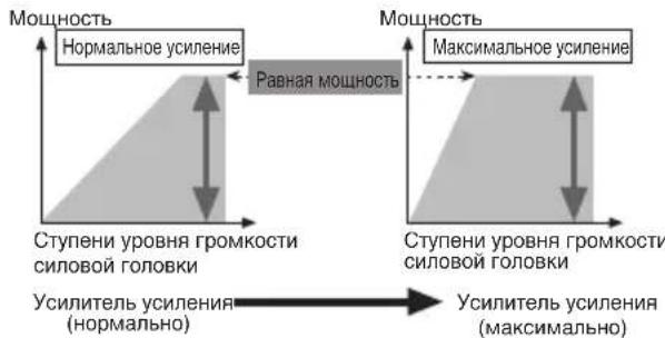
EcBbIOBbICHTe yCHJIeHHe yCHJIHTeJHa HEnPabHHbHbI yPOBeHb, yBEJIHHTcra TOJIbKO HCKaKeHHe, a MOUHOCt b yBEJIHHTcra He3HaHTeJIbHO.
ΦopMa CnHaJa, KOrJa BbIBOHTcB BbICOKn ypoBeHb rPOMKoCTN KOHTPOJeM ycJIeHnY ycJInteJr
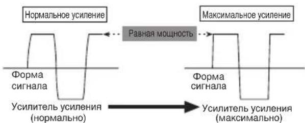
C BBICOKHM BbIXOJOM φopMa cHrHaJa HcKaXkaeTc, ecJH Bbl NOBbICHTe yCHJIeHHe YCHJIHTeJI, TO MOUHOCt b H3MeHHTc He3HaYHTeTbHO.
XOTBByyMeHbIaeTe yPOBeHb rPOMKoCTn CHIOBOI FOIOBKN H yCtHaBJIHBAeTe KOHTpOJIb YCHJIeHNr yCJITNEJI B NOxOJaIyU IO3NIIHO, a 3BYK BpeMg OT BpeMeHH IpoNaJaET, IOKaJIyIcTa, CBxHTEcB c JInxKaIWei ABTOPHOBAHHOI PIONEER STATION.

OCTOPOXHO!
- OToeHHHTe OTPHnateJIbHyO (-) KJEMMy 6aTapeH, TTO6bI He JOnyCTHTK KOPOTKORO 3aMbIKAHII NOBpeKDeHNy yCTpOHCTBa.
3aKpeHHe npObOa Ka6e.1hBIMn 3aKHMamH HJIN JHHKOJI
JeHTOn. JIa3aHHTb npOBoOB CcEyET O6MOTaBH XJHHKOJI
JeHTOn BTEX MeCTax, rne OHn cOpHKacaOTcC
MeTaJIJIuueckHMH YAcTAMH.
He paCnoIaraiTe npOBoBa MceTax,IOBBePKeHHbIX BO3dEeCTBHNO BMCOKO TEMpePaTybl, HAnpHMeP B TaKOM MeCTe, rIe Ha HHX MOKeT DeHCTBOBaTb HarPeTbN BO3yX H3 O6OrpeBaTeJI. HarpeBaHHe MOKeT pHBeCTH K IOBpeJDeHHO H3OJIaHH, Bpe3yJIbTaTe Yero MOKeT pOnH30HTN KOPOTKoe 3AmbKaHHe Ha KOpIyc ABtOMoHJI.
Y6eJIHTeCb B TOM, YTO IPOBOJa He MeIHaIOT JBHRAHOIHMCn YaCTAM ABTOMO6HII, HAnpHMeP, pBlyAry IpeK.IIOHeHHI KOp6Kn IpeJaq, pyHOMy TOPMO3y IIN MExaHH3My IpeEIBHXKeHH CHHeHH.
He ykopaHbaiTe KaKHe-JnHo npOBoJa. PInp YkopaHbAHHH npOBoJa IeB 3aHTb MoKeT He cpaOraTb HyKhbMOMeHT.
HnKorda He nOaBaiTe 3JekTpHHTaHHe Ha pyroe O6opyoBaHHe NocpeCTBOM CHrTH H30.7uHH IpOBoDA, NO KOTOPOMy IOnaetc 3JekTpHHTaHHe, HIOKJIHOueHH K 3TOMy npOBdy. IIpONyCKHa CnOCo6HoCtB IpOBoDA IO TOky 6yDet npEBbIeHa, YTO pINBeDET K neperpeBy.
HnKOrda He 3aMeHnIte neperopeBHH npeoxpaHHTeJIb npEOxpaHHTeJEM C66JbHMM HOMHHaJOM. HcnoJIb3OBaHHe HEIOXOJIIero npeoXpaHHTeJIM MOKeT IINBecTH K IIpePepBy H BbDEJENHO bIM.A. 3TO TAKJE MOKeT pNBecTH K IOBpeKJeHHO yCTPOHCTBA H TpaBMAM, B TOM YHCJIe OXORAM.

OCTOPOXHO!
Hnctpykunno npedynpejdeHHIO NOBpeJdeHn n/nn TpaBM
HnKorJa He 3a3eMJIaIe IPOBOJ HnHAMHKa HnIOcpeCTBeHHO H He IOkJIHOaIte OTPuataJIbHbI (-) IPOBOK HeCKoJIbKMn HnHaMHKa.
JaHHoe yctpoHCTBO IpeHa3HaeHo JIABTOMO6JIeIc 6batape12 BOJbT H OTPhaTeJbHbIM 3a3emJIeHNc. Ipeed ycTaHOBKOJ yCTPOHCTBa B TpaHCIOPTHom cpeICTBE JIJAOTbIXA, rpy3OBOM ABTOMO6JIe IJIH ABTOOyce Heo6X0JIMO IIPOBepHTb HanpJKeHHe batapeH.
Batape MoKet pa3pHHTc,ecJn ABTOMOHbHaMaHHTOJI npoIOJIkaeT paoTaTB B TeueHHe JOIIROTBpeMeHH IIH OTKJIHOeHHOM IIH paOToAHHE M BXJOCTOM peXHME DBHRatJe. He BKIOHaaTe ABTOMOHbHyO MaHHTOly,ecJH DBHRatJEb OTKJIHOeH IIH paOToaET B XJOCTOM peXHME.
EcIIINIPOBOI yCHJIHTeJI IJI INCTAHIOHOHORO YINpaBJIeHHN CHCTeMOI COeIHHEH C KJIEMMOI HcTOHHKA IIITAHN Yepe3 3AMOK 3aJHKraHHN (12 BIOCToHHORo TOka), yCHJIHTeJIb BCeRda 6yET BKJIOHYATbcI pIH BKJIOYHeHH 3aJHKraHHN, He3ABHCNOOToro, BKJIOYehA ABTOMOOJIbHA MaHHTOJa HJIH Het. IIO3TOMy 6atape MoKet pa3pIHTbcH, cJIH DnHrAteJIb OTKJIHOeH HIN pa0TaET B XJOIOCTOM peKHMe.
IIOJIJIHOaEMbE K yCHIHTeJHO HnHAMHKH JOIIXHbI COOTBETCTBOBATb HIXKHepePcHcJIeHHbIM CTAHapTAM. B cIyuae HecOOTBeTCTBnH DnHAMHKH MOrY 3aROpTeBcH IINH H3 HHX MOKeT IOHTbIM. 3TO TaKxMe MoKeT IIpHBcTH K IOBpeKJeHHIO DnHAMHKOB. POJIHOc COIpOTHBJEHeHc DnHAMHKOB IOJIKHO 6bITb B DnHaNa3OHe OT 2 OMO. OJHaKO JIA JByXKAHaTBbIX H HbIX MocTOBbIX CoeIHHeHHII POJIHOe COIpOTHBJEHe DnHAMKOB DOJIKHO 6bITb B DnHaNa3OHe OT 4 OMO. IO8OM.
- OTe.IbHO IpoIaBaEmb IIpoBOI 6aTapeH cJIeIyET pa3MeCTHTb KaK MoKHO JaIbIe OT IpoBOIOB HnHaMHKOB.OTJe.IbHO IpoIaBaEmb IIpoBOI 6aTapeH, IIpoBOI 3a3EmJIeHH, IIpoBOa DnHaMHOB H yCHITe. bCJIeYET pa3MeCTHTb KaK MoKHO Da.IbIIe OT aHTehHbI, Ka6JIra aHTehHbI H Tiohepa.
KaBeJIH DaHHORO yCTpoIcTBa HpyrHx yCTpoIcTB MOrYt 6bITb pa3HORO IBeTA, HeCMOTpRA Ha TO YTO, OHN BbIOJTHAOT OHHaKOBbIe FyHKUHN. PInH COeIHHeHH DAHHORO yCTpoIcTBa C npyrHM yCTpoIcTBOM, O3HaKOMbTEcB c HnCTpyKUHN M KaJDOrO yCTpoIcTBa H coeIHHHTe Ka6JIH, BbIOJHIOUHe OHHaKOBbIe fHyHKUHN.
BxOJHoe rHe3IO RCA A
BcIyuae HcnoJIb3OBAHnI DByXKaHaJIbHOrOpexKHaMa BCTaBbTe IITKepeRCA BO BXoJHOe rHe3IO RCA A.
MHORIO3HIOHOHHbI IpeKJIIOUaTeJB BXOJa
CDBHHbTe IpeKJIIOVAteJIb BJEBO.
OT aBTOMO6HJIbHOI MaHTTOJIb (BbIXoR RCA)
CoednHeHne KJIeMMbI nCTOuHnKa
NITAHNA
MbpeKOMeHnyem,HTO6bBbHCIOJIb3OBaJIH cIeIIaJIbHbIe KpaCHbIe IpoBOJa [RD-228]JJIa 6aTapeH H3a3cEMJIeHHa, KOtOpbIe IpoJaOTcra OTJeJIbHO. IOnCOeINHITe 3JIeKTpUYeCKHI IPOBOJ 6aTapeH IIpMAK IIJOIXHTeJIbHOI KJIeMMe (+) 6aTapeH ABTomObHJIa, a IpoBOJ 3a3cEMJIeHHa K Ky3OBy aBTOMoBHJIa.
- PekomehIOBAHHbIe IHaMeTpbl IpoBOIOB (AWG: AmePKaHckn KaJIN6p IpoBOIOB) cJIeIyIOIIHe. IpoBOI 6aTapeH II IPOBOI 3a3emJIeHNH II JOJXHbI 6bITb OINHAKOBOI DHaMeTpA.
HcnoJIb3yIte npOBoCeyEHemOT 10 AWG 20 AWG nIpaOBOa ChCTeMbI HnCTaHIOHOHorO ynpabJIeHH.
MaKcHMaJIbHaBbIXOJHaMoIIOHOCTb 100 Br×4(4Ω)/200 Br×2(4Ω)
HπpepbHbA BixOHa Ma MoHocTb 50BTx4 (piu 14,4B,4Ω,20TIO 20KΓo,obuee rapMOHueckoe hkaKeHne 0,08%)
PIONEER ELECTRONICS (USA) INC.
P.O. Box 1540, Long Beach, California 90801-1540, U.S.A.
TEL: (800) 421-1404
PIONEER EUROPE NV
Haven 1087, Keetberglaan 1, B-9120 Melsele, Belgium/Belgique
TEL: (0) 3/570.05.11
PIONEER ELECTRONICS ASIACENTRE PTE. LTD.
2 Jalan Kilang Barat, #07-01, Singapore 159346
TEL: 65-6378-7888
PIONEER ELECTRONICS AUSTRALIA PTY. LTD.
5 Arco Lane, Heatherton, Victoria, 3202, Australia
TEL: (03) 9586-6300
PIONEER ELECTRONICS OF CANADA, INC.
340 Ferrier Street, Unit 2, Markham, Ontario L3R 2Z5, Canada
TEL: 1-877-283-5901
TEL: 905-479-4411
PIONEER ELECTRONICS DE MEXICO S.A. DE C.V.
Blvd. Manuel Avila Camacho 138, 10 piso
Col.Lomas de Chapultepec, Mexico, D.F. 11000
Tel: 52-55-9178-4270, Fax: 52-55-5202-3714
Published by Pioneer Corporation.
Copyright © 2007-2016 by Pioneer Corporation. All rights reserved.
Publication de Pioneer Corporation.
Copyright © 2007-2016 Pioneer Corporation.
Tous droits de reproduction et de traduction réservés.


- Before Using This Product 1
- Setting the Unit 3
- Connecting the Unit 6
- Installation 12
- Specifications 14
- oduct
- Visit our website
- In case of trouble
- CAUTION
- WARNING
- Terminal Cover
- Badge
- BFC (Beat Frequency Control) Switch
- Power Indicator
- Input Select Switch
- Gain Control
- Setting the Gain properly
- Gain Control of This Unit
- Relationship between the gain of the amplifier and the output power of the head unit
- Signal waveform when outputting at high volume by the gain control of the amplifier
- To prevent damage and/or injury
- Connection Diagram
- Solderless Terminal Connections
- Connecting the Speaker Output Terminals
- Connecting the Speakers and Input Wires
- Four-channel mode
- Three-channel mode
- Two-channel mode (Stereo)
- Two-channel mode (Mono)
- Connecting the Power Terminal
- Pass the battery wire from the engine compartment to the interior of the vehicle.
- Connect the wires to the terminal.
- Put the wire ties in the slits and wrap the wire ties around the wires.
- To prevent malfunction and/or injury
- Example of installation on the floor mat or on the chassis
- Replacing the terminal cover
- Changing the Direction of the Badge
- Specifications
- Note:
- *Average current drawn
- Cneunpkaa.. 14
- Pocetnte haw caT
- http://www.pioneer-rus.ru
- IeuctBnB Cnyae BO3HKnHOBeHn npo6nem
- OCTOPOXHO!
- PPEyPExKDEHNE
- Kpbioka
- 3m6nema
- IpeeknouateBFC (nepeknouateBacToTb6neHna)
- Hdikatop nntaHn
- Mhorono3nOHHbI nepeKIOUaTeIb BXoJa
- PerynpoBaHne yCnJIeHnI
- PerynilpoBaHne YcJIeHnIdoJXHbIM 06pa30M
- KoHTpoJIb yCnJIeHnI DaHHoro npu6opa
- OTHOSeHne MExdy yCnJIeHNem ycNlTeIa N BbIXoHDH MOUHOCbIO CnIOBOI rOIOBKn
- ΦopMa CnHaJa, KOrJa BbIBOHTcB BbICOKn ypoBeHb rPOMKoCTN KOHTPOJeM ycJIeHnY ycJInteJr
- Hnctpykunno npedynpejdeHHIO NOBpeJdeHn n/nn TpaBM
- CoednHeHne KJIeMMbI nCTOuHnKa
- NITAHNA
- PIONEER ELECTRONICS (USA) INC.
- PIONEER EUROPE NV
- PIONEER ELECTRONICS ASIACENTRE PTE. LTD.
- PIONEER ELECTRONICS AUSTRALIA PTY. LTD.
- PIONEER ELECTRONICS OF CANADA, INC.
- PIONEER ELECTRONICS DE MEXICO S.A. DE C.V.
Brand : PIONEER
Model : PRSA900
Category : AV receiver