GW90823 - Remote control Gewiss - Free user manual and instructions
Find the device manual for free GW90823 Gewiss in PDF.
User questions about GW90823 Gewiss
0 question about this device. Answer the ones you know or ask your own.
Ask a new question about this device
Download the instructions for your Remote control in PDF format for free! Find your manual GW90823 - Gewiss and take your electronic device back in hand. On this page are published all the documents necessary for the use of your device. GW90823 by Gewiss.
USER MANUAL GW90823 Gewiss
Warning! The safety of this appliance is only guaranteed if all the instructions given here are followed scrupulously. These should be read thoroughly and kept in a safe place. The Chorus products must be installed in compliance with the requisites of standard CEI 64-8 for devices for domestic use and similar, in non-dusty atmospheres and where special protection against water penetration is not required. The GEWISS sales organisation is at your disposal for clarifications and technical information.
Gewiss SpA reserves the right to make changes to the product described in this manual at any time and without giving any notice.
Pack content
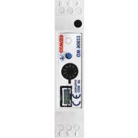
n. 1 GSM remote control unit interface - RF burglar alarm - DIN Rail
n. 1 8 wire cable with connectors which are polarized for connection to the remote control unit GSM, length 8 cm
n. 1 Rechargeable battery - Ni-MH 8.4V
n. 1 Installation and user manual
Summary
The GSM remote control unit interface - RF burglar alarm - DIN Rail is an extension of the GSM remote control unit (GW 90 821)
The interface is fitted with two radio modules, a receiver and a transmitter, which exchange information (commands, alarms and status) in both directions with the Gewiss wireless burglar alarm control unit (GW 20 470 and GW 20 481). It is therefore possible to use the remote control unit to remotely activate and deactivate the burglar alarm using a mobile phone and to receive alarm messages by SMS.
The interface is connected to the remote control unit by an 8 wire cable, which provides bidirectional data exchange and ensures the interface is powered by the remote control unit. The interface can not function by itself. The interface is mounted on a DIN rail, next to the remote control unit, inside electric panels or junction boxes.
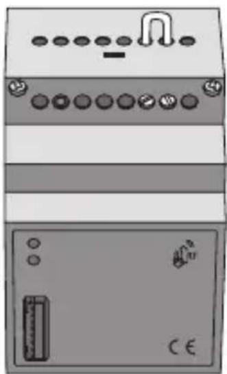
2 LEDs are assembled on the front of the interface with the functions seen below:
| Green LED | fixed light | Interface powered up and arm/disarm indicator is ON |
| flashing | Interface powered up and arm/disarm indicator is OFF | |
| Yellow LED | fixed light | Interface programming is ON (terminals 15 and 16 are shortcircuited) |
| flashing | Programming is ON and siren and actuator codes have been learned from the burglar control unit |
Please consult the GSM GW 90 821 remote control unit instruction manual for the list of functions available and the commands available by SMS.
INSTALLATION
WARNING: Only qualified personnel are permitted to install this device, according to the regulations in force.
Good wireless connection recommendations
- Install the interface in a "central" position in relation to the various RF devices it must dialogue with.
- Install the interface as far as possible from all sources of electromagnetic disturbances such as electrical motors, electricity meters, electrical appliances.
- Do not install the interface near or behind metal surfaces.
- Do not install the interface inside metal electrical panels or junction boxes mounted inside reinforced concrete walls.
Inserting the battery
WARNING: Only use 8.4 V Ni-MH rechargeable batteries, with a capacity ranging between 150 and 300 mAh. The use of other batteries may be hazardous and cause overheating and fires.
Place the buffer battery inside the interface as seen below:
- Open the interface by loosening the front screws and remove the front cover.
INSTALLATION
- Connect the battery to the polarized connector and fit it into its seat.
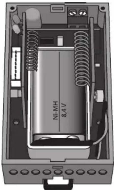
- Replace the front cover and tighten the screws to close it.
Assembly on a DIN rail
Fit the interface to a 35mm DIN rail as follows (figure B):
- Insert the device's upper coupling in the DIN rail.
- Rotate the device until a "click" is heard, signalling locking to the DIN rail.
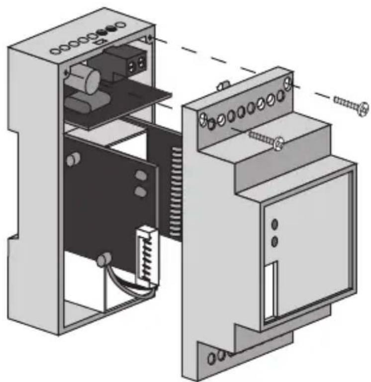
Electrical connections
WARNING: Disconnect all power to the remote control unit before connecting it up.
Connect the interface to the remote control unit using the 8 wire cable with polarized connectors. Figure C shows the electrical connections diagram.
Programming the interface
To programme the RF burglar alarm interface, please proceed as follows:
- Make sure that terminals 15 and 16 are short-circuited on the interface (the device leaves the factory with a jumper connected to the terminals).
- Power up the remote control unit and consequently the interface. The green and yellow LEDs light up: the green LED indicates that the power is ON and the yellow LED indicates that programming is also ON.
- Setting up the Gewiss wireless burglar alarm control unit to receive a remote control code.
- Press the programming button on the interface to generate a transmission. The burglar alarm control unit learns the burglar alarm RF interface remote control code.
- Setting up the burglar alarm control unit to transmit a siren code. The siren code generated by the control unit is learned by the burglar alarm RF interface and the yellow LED flashes for 5 seconds to indicate that the code has been learned.
- Setting up the burglar alarm control unit to transmit an actuator code. The actuator code generated by the control unit is learned by the burglar alarm RF interface and the yellow LED flashes to indicate that the code has been learned and that the programming phase is over.
- Remove the jumper from terminals 15 and 16 on the interface to conclude the programming procedure. The yellow LED will turn off when the operator exits the programming procedure.
IN SERVICE
Maintenance
This device requires no maintenance. Use a dry cloth if any cleaning is required.
Always remove the buffer battery if the interface is disconnected from the remote control unit for prolonged periods. Replace the buffer battery before connecting the interface to the remote control unit again.
This appliance requires a battery to function properly.
If the battery is replaced, make sure the old battery is disposed of according to the waste regulations foreseen by your local authorities.
TECHNICAL DATA
| RF communication frequency | 868 MHz |
| Power Supply | By connection to the remote control unit |
| Buffer battery | Ni-MH 8.4 V 150÷300 mAh |
| Connection to the remote | |
| control unit | 8 pole polarized socket |
| RF range on open field | 100 m |
| Control elements | 1 programming button |
| 1 programming jumper | |
| Display elements | 1 green LED - power ON indicator |
| 1 yellow LED - programming indicator | |
| Ambit of use | Indoors, dry places |
| Operating temperature | -5 ÷ +45 °C |
| Storage temperature | -25 ÷ +70 °C |
| Relative humidity | Max 93% (no condensation) |
| Protection rating | IP20 |
| Dimensions | 3 DIN modules |
| Reference standards | Low Voltage Standard 2006/95/CE |
| Electromagnetic Compatibility Standard 89/336/CEE | |
| , | R&TTE 99/05/CEE |
SOMMAIRE
page AVERTISSEMENTS GENERAUX 20
DESCRIPTION GENERALE 21
INSTALLATION 22
PROGRAMMATION 24
EN SERVICE 25
DONNEES TECHNIQUES 26
AVENTISSEMENTS GENERAUX
The device is also compatible with the new burglar alarm control unit GW 10 931; for the configuration, refer to the control unit programming manual.