
GW90822 - Remote control Gewiss - Free user manual and instructions
Find the device manual for free GW90822 Gewiss in PDF.

| Product Type | Interface for GSM-RF remote command and control system |
| Brand | Gewiss |
| Model | GW90822 |
| Dimensions | 1 DIN module (width 17.5 mm, height 90 mm, depth 58 mm) |
| Power supply | By connection to the remote control system via 4-conductor cable |
| RF communication frequency | 868 MHz |
| RF range in open field | 100 m |
| Number of RF transmission channels | 5 |
| Number of RF reception channels | 2 |
| Number of bidirectional channels | 1 |
| Main functions | Control of RF actuators (up to 5 groups), reception of states from RF input devices, management of bidirectional RF chronothermostat |
| Control elements | 1 miniature programming button, 1 10-position rotary selector |
| Display elements | 1 multifunction LED (red/green/yellow) |
| Operating environment | Indoor, dry places, dust-free, no water spray |
| Operating temperature | -5 to +45 °C |
| Storage temperature | -25 to +70 °C |
| Relative humidity | Max. 93% (without condensation) |
| Degree of protection | IP20 |
| Installation | On 35 mm DIN rail, in electrical panel or junction box |
| Maintenance and cleaning | No maintenance required; clean with a dry cloth |
| Safety | Installation reserved for qualified personnel; comply with standard IEC 64-8 |
| Package contents | Interface, 4-conductor cable (8 cm), installation and user manual |
Frequently Asked Questions - GW90822 Gewiss
User questions about GW90822 Gewiss
0 question about this device. Answer the ones you know or ask your own.
Ask a new question about this device
Download the instructions for your Remote control in PDF format for free! Find your manual GW90822 - Gewiss and take your electronic device back in hand. On this page are published all the documents necessary for the use of your device. GW90822 by Gewiss.
USER MANUAL GW90822 Gewiss
N. canali transmission RF 5
Warning! The safety levels of this device can only be guaranteed if these instructions are fully observed. It is therefore essential to carefully read and keep them for future reference. All Chorus products must be installed in compliance to CEI 64-8 Standards for household appliances and similar items, in dust-free environments where no special protection is required to prevent penetration of water.
The GEWISS sales division is at your complete disposal for any further technical details or information you may require.
Gewiss SpA reserves the right to make any modifications to the products described in this manual at any time without prior warning.
Contents of the pack
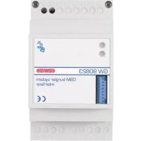
n. 1 GSM remote control unit interface - RF command and control - DIN rail
n. 1 4 wire cable with connectors which are polarised for connection to the remote interface GSM, length 8 cm
n. 1 Installation and user manual
Summary
The GSM remote control unit interface - RF command and control - DIN rail is an extension of the GSM remote control unit (GW 90 821)
The interface is fitted with two radio modules, a receiver and a transmitter, which exchange information (commands and status) in both directions with the Gewiss wireless command and control unit. It is therefore possible, with the repeating and exchange of SMS messages, to remotely command and control the Gewiss wireless system.
The interface is connected to the remote control unit by a 4 pole connector, which provides bidirectional data exchange and ensures the interface is powered by the repeater. The interface can not function by itself.
The interface is mounted on a DIN rail, next to the remote control unit, inside electric panels or junction boxes.
Functions
The interface can interact with the following Gewiss RF devices:
ACTUATORS
When the interface receives a command from the remote control unit, it generates RF commands which can be interpreted by the following RF devices: 1 channel 3A actuator (for instance GW 14 821), 1 channel 16A actuator (for instance GW 14 822) and a motor command actuator (for instance GW 14 823). According to how the actuator is configured, it is possible to obtain the following functions:
- activation and deactivation of electrical loads, such as the on and off command for lights;
- timed commands, for instance the on and off command for stairway lighting;
motor command, for instance to operate a shutter.
The actuator can only receive commands and therefore the communication between the interface and the actuator is unidirectional.
The interface can control up to five groups of actuators separately. When the interface transmits the RF command, the multi-function LED flashes green once.
INPUT DEVICES
The interface can receive status signals from the following Gewiss RF devices: 2 channel input module (for instance GW 14 813), 1 channel command push-button panel (for instance GW 14 801), 2 channel command push-button panel (for instance GW 14 802), 3 channel command push-button panel (for instance GW 14 803), 4 channel command push-button panel (for instance GW 14 804), IR twilight movement detector (for instance GW 14 811) and a remote control (GW 20 963).
The interface has 2 input channels; up to four different transmission channels can be connected to each of them and the interface will manage them in an identical manner. When the interface receives a message, it forwards the information received to the remote control unit which will perform the relative actions.
When the interface receives a RF message, the multi-function LED flashes green once.
RF BI-DIRECTIONAL TIMED-THERMOSTAT
The interface can transmit commands to the wall-mounted RF bi-directional Timed-thermostat (GW 10 851 - GW 14 851) which control the function settings (heating/air conditioning) the thermal regulation system function settings (manual/auto/OFF) and the manual temperature set points received from the remote control unit.
The interface can then send the status information received from the Timed-thermostat to the remote control unit so that they are then remotely sent by GSM.
The information sent include:
- function type (heating/air conditioning);
- function mode (auto/manual/OFF);
- set operating temperatures;
- room temperature;
- final command sent to the actuator which controls the boiler.
If the batteries are low, this warning will also be sent with the other information. Given that the interface and the Timed-thermostat must exchange a lot of information and the Timed-thermostat uses energy saving techniques to increase the battery life, the SMS reply can be delayed by up to 10 minutes from the status request.
The interface can only handle one RF bi-directional Timed-thermostat.

WARNING: only qualified personnel are permitted to install this device, according to the regulations in force.
Good wireless connection recommendations
- Install the interface in a "central" position in relation to the various RF devices it must dialogue with.
- Install the interface as far as possible from all sources of electromagnetic disturbances, such as electrical motors, electricity meters, electrical appliances.
- Do not install the interface near or behind metal surfaces.
- Do not install the interface inside metal electrical panels or junction boxes mounted inside reinforced concrete walls.
If radio connection difficulties occur it is recommended to connect external aerials, as illustrated in the "External aerial connection".
External aerial connection
If the RF connection with other installed devices is difficult, it is possible to connect external aerials to the interface which can be positioned in areas which receive better RF signals.
This solution can, for instance, be used when the interface is shielded by metal surfaces. It is possible to connect external aerials for transmission (TX) and reception (RX) purposes, as required.
PREPARED THE AERIAL WITH THE CONNECTION CABLE
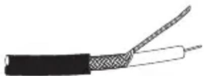
To create an aerial, use a 50 ohm shielded coaxial cable, for example RG-58, which is maximum 2 metres long, following the instructions below:
- Prepare the end of the cable which will act as an aerial by removing 7.5cm of the external sheath and the shield braid, leaving the dielectric intact.
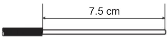
- Remove about 3cm of sheath from the other end, twist the shielding and free the cable core cutting about 1cm of the dielectric.
INSTALLATION
SELECTING EXTERNAL AERIALS
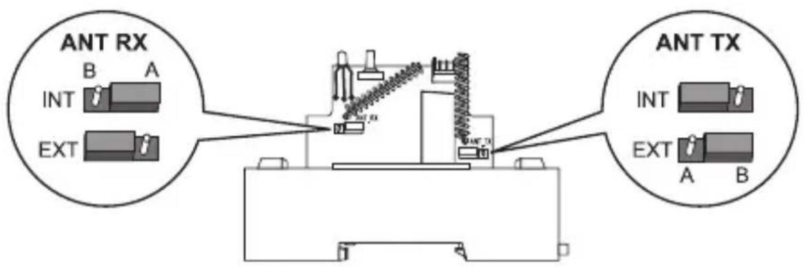
The factory settings on the interface foresee the use of internal aerials. To activate the external aerial connections proceed as follows.
- Open the interface by loosening the fastener screw and remove the top cover.
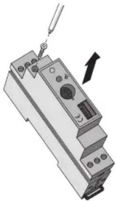
- Move the jumper that is on the card to activate the reception (ANT RX) and transmission (ANT TX) external aerial (EXT) connections.
- Replace the cover on the interface and tighten the screw to close it.
CONNECTING THE AERIALS
Proceed as follows to connect the previously created aerials to the interface:
- transmitter aerial: core = terminal 2, shielding = terminal 1 or 3;
- receiver aerial: core = terminal 5, shielding = terminal 4 or 6.
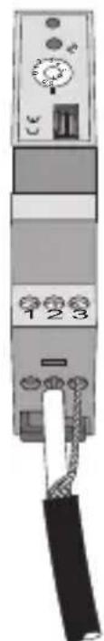
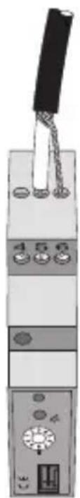
Transmitter aerial (TX) Receiver aerial (RX)
Assembly on the DIN rail
Assembly the interface onto a 35mm DIN rail as follows (figure B):
- Insert the device's upper coupling in the DIN rail.
- Rotate the device until you hear a "click" that means that the DIN rail is blocked in place.
Electrical connections

WARNING: Disconnect all power to the remote control unit before connecting it up.
Connect the interface to the remote control unit using the 4 wire cable with polarized connectors. Figure C illustrates the electrical connection layout.
PROGRAMMING
Before starting to configure the interface, check that the remote control unit and the RF devices are all powered up (the remote control unit does not have to be configured at this stage).
Combining actuators
To combine an actuator to the interface (or a group of actuators that respond to the same command), proceed as follows:
- Turn the rotating switch on the interface to one of the position from 1 to 5.
- Place the actuator in learning mode.
- Press the front button on the interface: a RF message will be sent which the relative actuator will then learn. The multi-function LED will flash green once. Exit the actuator learning mode.
- If you wish to memorise other actuators on the same channel, repeat points 2 and 3 for each of the devices. If you wish to combine other groups of actuators, first turn the switch to another position (from 1 to 5) and repeat the instructions from point 2 onwards.
- Turn the rotating switch on the interface to position 8 for standard operations.
Combining input devices
To combine one or more RF input device channels to the interface, proceed as follows:
- Turn the rotating switch on the interface to position 6 or 7. The multi-function LED on the interface will indicate a red fixed light.
- Activate the transmission channel you wish to memorise by pressing the relative button (or by making the sensor intervene, if it is a wireless twilight IR movement detector).
- The interface LED will go off. After a few seconds it will come on again: if there is a fixed red light it is possible to learn a new input, repeating the procedure from point 2; if there is a flashing yellow light the memory is full (4 inputs memorised on the same channel).
- If it is necessary to combine other devices, turn the switch to the position which is still free for the input devices (6 or 7) and repeat the procedure from point 2.
- Turn the rotating switch on the interface to position 8 to return to standard operating mode.
Combining the RF bi-directional timed-thermostat
To combine the RF bi-directional timed-thermostat, please proceed as follows:
- Turn the rotating switch on the interface to position 0. The multi-function LED on the interface will indicate a red fixed light (if the LED flashes this indicates that a timed-thermostat has already been memorised).
- Place the timed-thermostat in learning mode by pressing the , and buttons all together.
- Press the button on the front of the interface to send a RF message that will be learned by the timed-thermostat. The multi-function LED on the interface will flash green once to confirm the transmission.
- Press the , and buttons all together to send a message to the timed-thermostat. Confirmation of message transmission is indicated briefly on the display by a symbol (RF transmission).
- When the learning procedure is over, the multi-function LED on the interface will flash yellow to warn that it is not possible to combine another timed-thermostat.
- Turn the rotating switch on the interface to position 8 to return to standard operating mode.
Cancelling combinations
To cancel the combinations memorised on the interface, turn the rotating switch to position 9: the multi-function LED will flash yellow for 10 seconds and then remain ON (yellow) to indicate that all the channel combinations have been cancelled.
To interrupt the cancellation procedure, turn the selector switch to another position before the LED stops flashing.

WARNING: It is not possible to perform selective cancellations: the cancellation operation requires all the combinations to be repeated.
IN SERVICE
Maintenance
This device requires no maintenance. Use a dry cloth if any cleaning is required.
RF communication frequency 868 MHz
Power By connection to the remote control unit
Connection to the remote control unit 4 pole polarized socket
N. of RF transmission channels 5
N. of RF reception channels 2
N. of bi-directional channels 1
RF range on open field 100m
Control elements 1 mini programming key
1 10-position rotating switch:
0→timed-thermostat learning
1...5 →RF actuator learning
6...7 RF input module learning
8 standard operating mode
9 cancellation of combinations
Display elements 1 multifunction LED (red-green-yellow)
Ambit of use Indoors, dry places
Operating temperature -5 ÷ +45 °C
Storage temperature -25 ÷ +70 °C
Relative humidity Max 93% (no condensation)
Protection rating IP20
Sizes 1 DIN module
Reference Standards Low Voltage Directive 2006/95/EC:
Electromagnetic Compatibility Standard
89/336/EC
R&TTE 99/05/CEE, EN50428, EN50090
SOMMAIRE
page AVERTISSEMENTS GENERAUX 4
DESCRIPTION GENERALE 5
INSTALLATION 7
PROGRAMMATION 10
EN SERVICE 12
DONNEES TECHNIQUES 13
AVERTISSEMENTS GENERAUX
- Contents of the pack
- Summary
- Functions
- ACTUATORS
- INPUT DEVICES
- RF BI-DIRECTIONAL TIMED-THERMOSTAT
- Good wireless connection recommendations
- External aerial connection
- PREPARED THE AERIAL WITH THE CONNECTION CABLE
- INSTALLATION
- SELECTING EXTERNAL AERIALS
- CONNECTING THE AERIALS
- Assembly on the DIN rail
- Electrical connections
- PROGRAMMING
- Combining actuators
- Combining input devices
- Combining the RF bi-directional timed-thermostat
- Cancelling combinations
- IN SERVICE
- Maintenance
- SOMMAIRE
- AVERTISSEMENTS GENERAUX
Brand : Gewiss
Model : GW90822
Category : Remote control