
KS1300HT - Speakers KENWOOD - Free user manual and instructions
Find the device manual for free KS1300HT KENWOOD in PDF.

| Brand | Kenwood |
| Model | KS1300HT |
| Product type | Speaker system (front, center, and surround speakers) |
| Configuration | 5.0 channels (2 front, 1 center, 2 surround) |
| Acoustic system | Bass Reflex |
| Speaker type | 70 mm cone |
| Nominal impedance | 8 Ω |
| Peak input power | 120 W |
| Sensitivity (front/center speaker) | 84 dB/W/m |
| Sensitivity (surround speaker) | 83 dB/W/m |
| Frequency response | 140 Hz – 20 000 Hz |
| Magnetic shielding | Yes (front and center speakers) |
| Dimensions front speaker (W × H × D) | 91 × 180 × 93 mm |
| Dimensions center speaker (W × H × D) | 180 × 91 × 93 mm |
| Dimensions surround speaker (W × H × D) | 91 × 180 × 93 mm |
| Weight front speaker | 0.6 kg |
| Weight center speaker | 0.6 kg |
| Weight surround speaker | 0.5 kg |
| Power supply | Passive (via external amplifier) |
| Mounting methods | Shelf, wall (screw), optional bracket SR-8000 (front/surround), commercial wall mount (front) |
| Maintenance | Clean with a dry, clean cloth; do not use solvents |
| Safety instructions | Avoid water, humidity, heat; do not modify; unplug if abnormal smell |
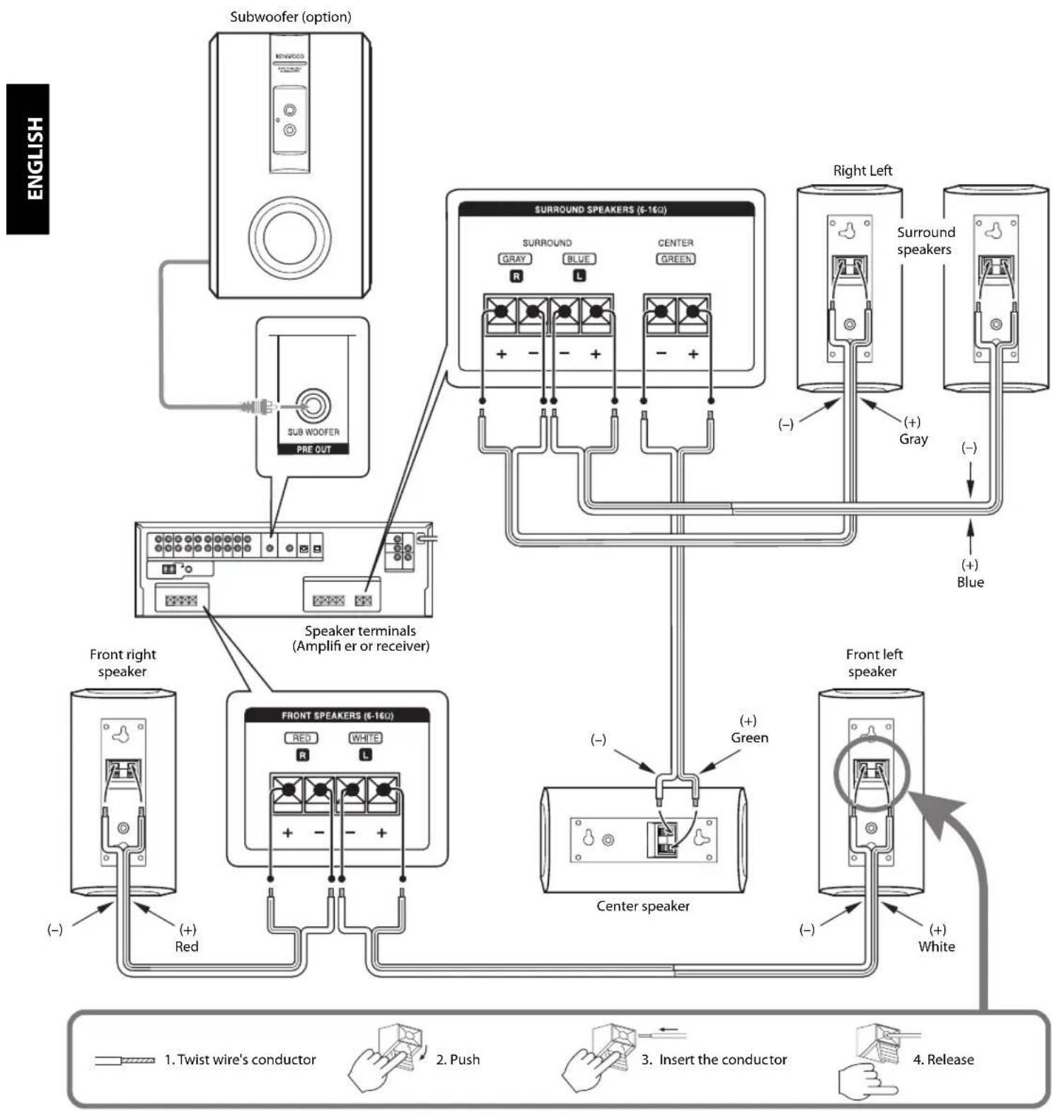
| Included accessories | Speaker cables (red 4 m, white 4 m, blue 8 m, gray 8 m, green 3 m), 20 cushions |
| WEEE information | Do not dispose of with household waste; recycle at a suitable collection point |
Frequently Asked Questions - KS1300HT KENWOOD
User questions about KS1300HT KENWOOD
0 question about this device. Answer the ones you know or ask your own.
Ask a new question about this device
Download the instructions for your Speakers in PDF format for free! Find your manual KS1300HT - KENWOOD and take your electronic device back in hand. On this page are published all the documents necessary for the use of your device. KS1300HT by KENWOOD.
USER MANUAL KS1300HT KENWOOD
Thank you for selecting our speakers as part of your high-fidelity system. We at Kenwood are confident that your choice will bring you years of rich listening pleasure. Please take the time to read through this booklet carefully. It will help you to obtain the peak performance for which the speakers were designed.
For your records
Record the serial number, found on the back of the unit, in the spaces designated on the warranty card, and in the space provided below.
Refer to these model and serial numbers whenever you call upon your Kenwood dealer for information or service on this product.
Model KS-1300HT is composed of the front speakers, center speaker and surround speakers.
KS-1300HT Serial number
IMPORTANT SAFETY INSTRUCTIONS

Caution: Read this item carefully to keep your safety.
- Suffocation – After taking the unit out of the polyethylene bag, be sure to dispose of the polyethylene bag out of the reach of children. Otherwise, they may play with the bag, which could cause hazard of suffocation.
- Water and moisture – The appliance should not be used near water - for example, near a bathtub, washbowl, kitchen sink, laundry tub, in a wet basement, or near a swimming pool, etc.
-
Heat - Do not install the unit near a source of heat, such as radiators, or under direct sunlight.
-
Modification - Do not attempt to open or modify the unit, for this could cause fi re hazard or malfunction.
- Cleaning - Do not use volatile solvents such as alcohol, paint thinner, gasoline, or benzine, etc. to clean the cabinet. Use a clean dry cloth.
- Abnormal smell – If an abnormal smell or smoke is detected, immediately turn the power OFF and unplug the appliance from the wall outlet. Contact your dealer or nearest service center.
Installation
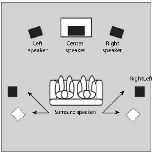
This speaker system can provide full Surround sound. To enjoy the full effect of the Surround sound field, please position the speakers as described below.
- Place the left and right speakers at each side of your TV. Angle the speakers towards the listening area to enhance the stereo effect.
- Place the center speaker on the center between the front left and right speakers. Tilt the speaker upward or downward so that it is directly facing the listening area.
- Place the surround speakers as high as possible, either directly to the sides of the listening area or else slightly behind the listening area. Adjust the angles so that these speakers are facing directly towards the listeners.
Positioning For Optimal Surround Sound
flowchart
graph TD
    A["Left speaker"] --> B["Center speaker"]
    C["Right speaker"] --> D["Surround speakers"]
    E["RightLeft"] --> F["Surround speakers"]
    B --> G["Square icon"]
    D --> H["Square icon"]
    F --> I["Square icon"]
About Using Speakers Near a TV (Front speaker, Center speaker)
This speaker include magnetic shielding and can therefore be installed close to a TV set. Note, however, that placing speakers too close to a TV may in some cases produces distortion in the color reception. In such case, turn on the TV and check that color reproduction is normal. If color is distorted, turn the TV off for 15 to 30 minutes, then turn it back on and check again. (This allows the TV's degaussing circuitry to correct for the magnetic field from the speakers.) If distortion is still present, move the speakers further from the TV.
Installation Methods
On the Desktop or Shelf
Place the speakers on the desktop, shelf or a similar level surface.
On the Wall
The speakers include mount holes for wall mounting. You can hang the front and surround speakers on the wall vertically, and the center speaker horizontally.
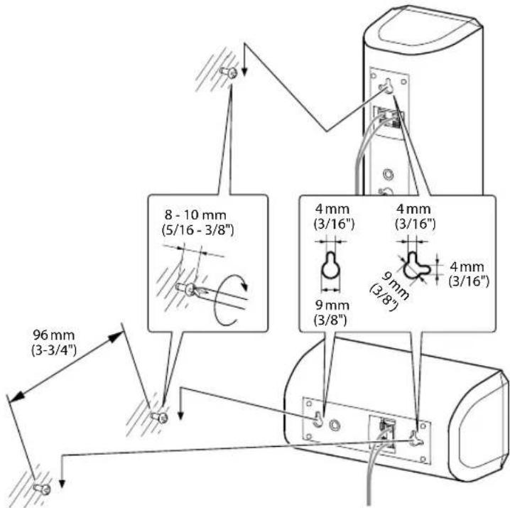
■ Front speaker, Surround speaker
-
Screw a single screw into the wall at the desired location. Screw it only part way in, so that the screw projects 8 to 10 mm (5/16 to 3/8 inches) outward from the wall surface.
-
Hang the speaker by fitting the top mount hole (at the upper rear of the speaker) over the extending part of the screw. Confirm that the speaker is held firmly and securely in place.
■ Center speaker
-
Screw two screws into the walls 96 mm (3-3/4 inches) apart, making sure that screws are horizontally level. Screw each screw only part way in, so that the screw projects 8 to 10 mm (5/16 to 3/8 inches) outward from the wall surface.
-
Hang the speaker by fitting the two mount holes (at the rear of the speaker) over the extending part of the screw. Confirm that the speaker is held firmly and securely in place.
Various mounting methods
■ On the optional Kenwood stand (SR-8000) (front speaker and surround speaker only)
The speaker can be installed on the SR-8000 stand optionally available from Kenwood.
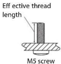
■ On the commercially available speaker mount or bracket (front speaker only)
Any commercially available speaker mount or bracket can also be used (provided that the speaker can be fixed using an M5 screw with a pitch of 60 mm and effective thread length of 10 to 13 mm).
For details, read the instruction manual for the speaker mount or bracket.
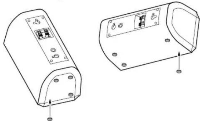
Attaching the cushions
Attach cushions to the base of the speaker as shown below. The cushions prevent the speaker from sliding, and dampen its vibrations.
Front speaker, Center speaker
Surround speaker
natural_image
Technical line drawing of two electronic device casing components with mounting holes and internal circuit breakers (no text or symbols)Precautions
Please observe the following precautions when mounting speakers onto the wall or speaker stand.
- Be sure that the wall you are using is strong enough to support the full weight of the speaker (approx. front speaker: 0.6 kg [1.3 lb], center speaker: 0.6 kg [1.3 lb], surround speaker: 0.5 kg [1.1 lb]).
• Wall screws must be purchased separately. - Be sure to use screws that are appropriate for the wall or stand you are using, and that are long enough to provide sufficient strength.
- If you are uncertain about the wall's support strength, the type of screw to use, or any other points regarding this type of installation, please consult a contractor or other qualified person before proceeding.
Be sure to follow the procedure given here when carrying out installation. Kenwood can assume no liability for injury or damage that may occur if a speaker setup falls from the wall as a result of incorrect installation or insufficient support strength.
The speaker wires and labels of speakers' back panel are color-coded to facilitate connection. Connect each wire to the matching-colored terminal, as shown in the figure.
Be sure to turn off your amplifier before connecting or disconnecting speakers.
flowchart
graph TD
    A["English"] --> B["Subwoofer (option)"]
    B --> C["SUB WOOFER PRE OUT"]
    C --> D["Speaker terminals (Amplifier or receiver)"]
    D --> E["Front right speaker"]
    D --> F["Front SPEAKERS (6-160)"]
    F --> G["Red White R L"]
    F --> H["Center speaker"]
    H --> I["White Right Left"]
    H --> J["White Front left speaker"]
    K["English"] --> L["Switch to Twist wire's conductor"]
    K --> M["Push to Push"]
    K --> N["Insert the conductor"]
    K --> O["Release to Hand with hands"]
Notes:
- The speaker system's peak input power is indicated in the specifications. To avoid speaker damage, never run the speakers at power levels exceeding this limit.
- This speaker system has a nominal impedance of 8 ohms. To ensure safe and reliable operation, be sure that your amplifier or receiver is able to work with 8-ohm speakers.
- Never short the (+) and (−) speaker wires together.
- Do not reverse L and R or (+) and (−) connections. Reversal of sides or polarities may result in unnatural, incorrectly positioned sound.
The following ratings and design are subject to change without notice.
Front speaker
System....Full-range speaker system (Magnetically shielded)
Enclosure ...... Bass-Reflex
Loudspeaker 70 mm (2-3/4") Cone type
Nominal Impedance 8 Ω
Peak Input Power 120W
Sensitivity 84 dB / W at 1 m
Frequency Response 140 Hz \~ 20,000 Hz
Dimensions
Width 91 mm (3-9/16")
Height.... 180 mm (7-1/16")
Depth....93 mm (3-11/16")
Net Weight 0.6 kg (1.3 lb) /piece
Center speaker
System....Full-range speaker system (Magnetically shielded)
Enclosure ...... Bass-Reflex
Loudspeaker 70 mm (2-3/4") Cone type
Nominal Impedance 8 Ω
Peak Input Power 120W
Sensitivity 84 dB / W at 1 m
Frequency Response 140 Hz \~ 20,000 Hz
Dimensions
Width 180 mm (7-1/16")
Height....91 mm (3-9/16")
Depth....93 mm (3-11/16")
Net Weight 0.6 kg (1.3 lb) /piece
Surround speaker
System......Full-range speaker system
Enclosure Bass-Reflex
Loudspeaker 70 mm (2-3/4") Cone type
Nominal Impedance 8 Ω
Peak Input Power 120W
Sensitivity 83 dB / W at 1 m
Frequency Response 140 Hz \~ 20,000 Hz
Dimensions
Width 91 mm (3-9/16")
Height.... 180 mm (7-1/16")
Depth.... 93 mm (3-11/16")
Net Weight 0.5 kg (1.1 lb) /piece
Accessories
Speaker wire
Red 4 m (13 ft)
White 4 m (13 ft)
Blue 8 m (26 ft)
Gray 8 m (26 ft)
Green 3 m (9 ft)
Cushion 20 pcs
Note:
The grilles on all the speakers cannot be removed.
Information on Disposal of Old Electrical and Electronic Equipment (applicable for EU countries that have adopted separate waste collection systems)

Products with the symbol (crossed-out wheeled bin) cannot be disposed as household waste.
Old electrical and electronic equipment should be recycled at a facility capable of handling these items and their waste by products.
Contact your local authority for details in locating
a recycle facility nearest to you.
Proper recycling and waste disposal will help conserve resources whilst preventing detrimental effects on our health and the environment.
natural_image
Technical line drawing of two electronic device casing components with mounting holes and internal circuitry (no text or symbols)Précautions
natural_image
Technical line drawing of two electronic device components with mounting holes and internal circuitry (no text or symbols)Vorsichtsmaßnahmen
natural_image
Technical line drawing of two electronic device casing components with mounting holes and internal circuit breakers (no text or symbols)natural_image
Technical line drawing of two electronic device casing components with mounting holes and internal circuitry (no text or symbols)Precauzioni
natural_image
Technical line drawing of two electronic device components with mounting holes and mounting points (no text or symbols)Precauciones
natural_image
Illustration of a notepad with lines of text and a pen resting on it (no readable text or symbols)
natural_image
Illustration of a notepad with lines of text and a pen resting on it (no readable text or symbols)
- For your records
- IMPORTANT SAFETY INSTRUCTIONS
- Caution: Read this item carefully to keep your safety.
- Installation
- Positioning For Optimal Surround Sound
- About Using Speakers Near a TV (Front speaker, Center speaker)
- Installation Methods
- On the Desktop or Shelf
- On the Wall
- ■ Front speaker, Surround speaker
- ■ Center speaker
- Various mounting methods
- ■ On the optional Kenwood stand (SR-8000) (front speaker and surround speaker only)
- ■ On the commercially available speaker mount or bracket (front speaker only)
- Attaching the cushions
- Precautions
- Notes:
- Front speaker
- Center speaker
- Surround speaker
- Accessories
- Précautions
- Vorsichtsmaßnahmen
- Precauzioni
- Precauciones
Brand : KENWOOD
Model : KS1300HT
Category : Speakers