LE900 - Voice recorder Lupus Electronics - Free user manual and instructions
Find the device manual for free LE900 Lupus Electronics in PDF.
| Product Type | Network Digital Video Recorder (DVR) |
| Brand | Lupus Electronics |
| Model | LE900 |
| Number of supported cameras | Up to 4 IP cameras |
| Power Supply | AC adapter 100-240V AC, 50/60Hz, with power cord |
| Network Connectivity | 2 Gigabit LAN ports (LAN1 fixed IP, LAN2 PPPoE/DHCP/fixed IP) |
| Internal Storage | SATA hard drive (not included, mounting bracket and screws included) |
| Client Software | MXR Client Software on CD (compatible Windows XP/Vista/7) |
| Minimum PC Configuration | Pentium 4 3.2 GHz, 1 GB RAM, 128 MB DirectDraw graphics card, 10/100/1000 Ethernet card |
| Main Functions | Live monitoring, continuous and event recording, playback, search, export, PTZ, two-way audio |
| Display Modes | Full screen, screen split (grid), click-and-drag zoom |
| Recording | Server and client, scheduling, motion detection, alarms |
| Playback | Local, real-time, download and playback; slow/fast speeds, event search |
| Export | Screenshot (jpg/bmp), print, video clip (mpg/avi/dvr), USB/DVD backup |
| Related Devices | 4 sensor inputs, 1 alarm output, audio input/output, USB port for external hard drive |
| Standards and Certifications | CE, RoHS, WEEE |
| Included Accessories | Software CD, user guide, hard drive mounting bracket with screws, AC adapter, power cord |
Frequently Asked Questions - LE900 Lupus Electronics
User questions about LE900 Lupus Electronics
0 question about this device. Answer the ones you know or ask your own.
Ask a new question about this device
Download the instructions for your Voice recorder in PDF format for free! Find your manual LE900 - Lupus Electronics and take your electronic device back in hand. On this page are published all the documents necessary for the use of your device. LE900 by Lupus Electronics.
USER MANUAL LE900 Lupus Electronics
natural_image
White electronic device labeled 'LUGU' with ports and indicator lights (no readable text beyond branding)(1)

(2)

(3)

(4)
natural_image
Black rectangular electronic device with attached cable and connector (no visible text or symbols)(5)
(6)
natural_image
Close-up of hands holding a white electronic device with red arrows indicating upward motion (no text or symbols visible)natural_image
Exterior view of a hard disk drive with visible internal components and mounting base (no text or symbols)natural_image
Close-up of hands installing a hard disk into an open circuit board (no visible text or symbols)natural_image
Hand using a screwdriver to adjust or install an open hard disk drive into a circuit board (no visible text or symbols)natural_image
Close-up of hands holding a white electronic device labeled 'AVarMedia' with red arrows pointing to its side (no readable text or symbols on the device itself)Lokale Wiedergabe


natural_image
White LUPUS wireless device with ports and indicator lights (no visible text or symbols on body)natural_image
White electronic device labeled 'LUPUS' with ports and indicator lights (no readable text beyond branding)(1)

(2)

(3)
(4)
natural_image
Black rectangular electronic device with attached cable and connector (no visible text or symbols)(5)
(6)
natural_image
Two hands holding a white electronic device with red arrows indicating upward motion (no text or symbols visible)natural_image
Exterior view of a hard disk drive with visible internal components and mounting holes (no text or symbols)natural_image
Close-up of hands installing a hard disk into an open circuit board (no visible text or symbols)natural_image
Hand inserting a hard disk into an open circuit board with visible internal components (no text or symbols)natural_image
Close-up of hands holding a white electronic device with red arrows pointing to the top panel (no visible text or symbols on the device itself)(4) EMap
Lecture en mode Lecture Locale
(11) Audio Activer/Désactiver la lecture audio
Thank you for your purchase of your brand new LE900 NVR.
Please read the manual carefully before the first activation and keep it at a safe place for further usage. The documentation, images and technical specifications are subject to change.
Please read the manual carefully before the first activation and keep it at a safe place for further usage or in case of giving the device to third persons.

The flash symbol in a triangle indicates danger of electric shock. Never open the dvr g or the housing of the supplied power adapter.
In case of malfunction
In case of malfunction, please pull the powerplug and contact your dealer. Further usage may increase the risk of fire or electric shock.
Intended usage
The dvr is intended for conventional video surveillance by day and night. It is designed for indoor use. Please make sure that privacy rights of third persons be not infringed at any time. The surveillance of persons without their explicit knowledge and consent is prohibited by law in many countries.
This product must not be used for any other purpose save those set out in the user manual.
Contravention may lead to loss of warranty and guarantee as well as the exclusion of liability. This includes changes to and modifications of the product.

Orderly disposal:
Do not dispose of this product with your domestic waste!
This device complies with the EU regulation on electronic waste and therefore must not be disposed of with domestic waste. Please dispose of this product with your local waste disposal for electronic devices.
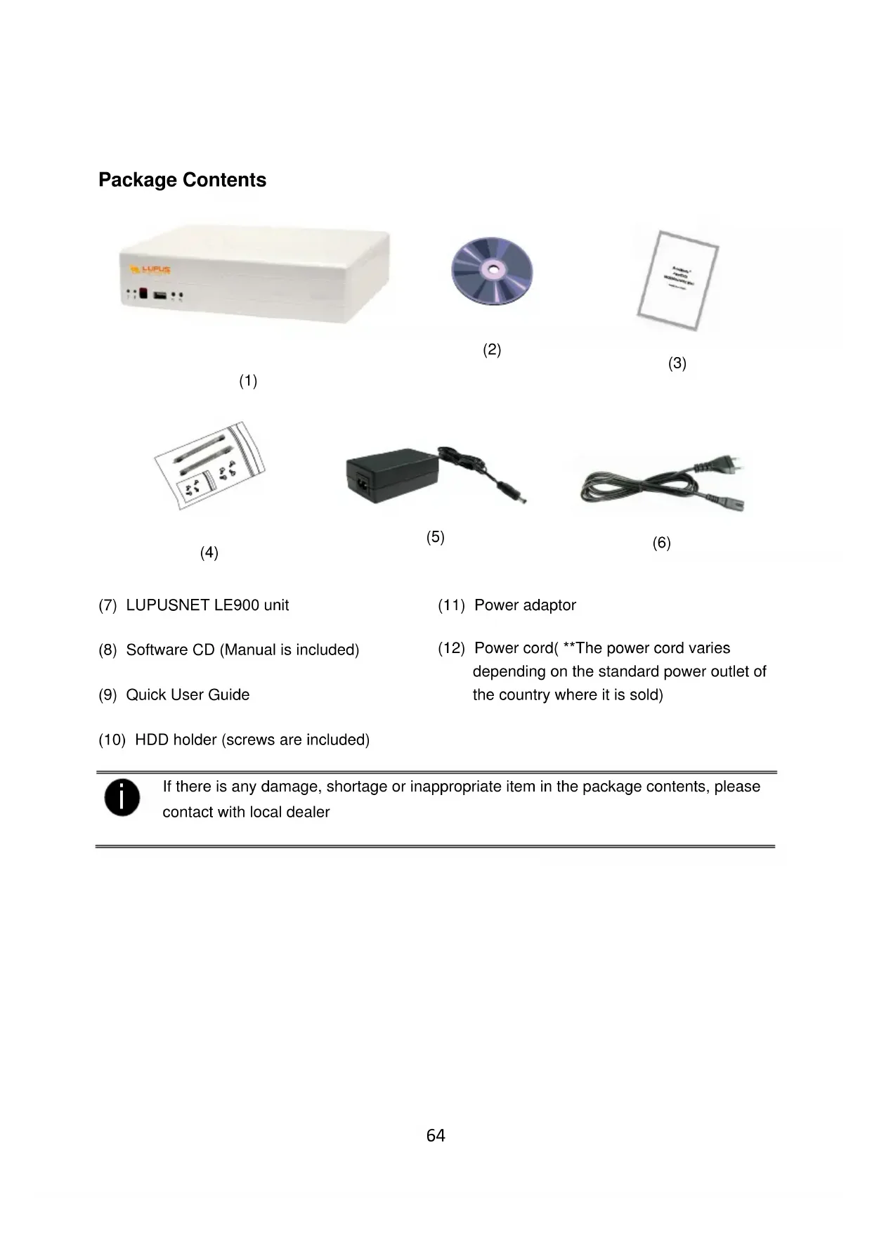
Package Contents

natural_image
White electronic device labeled 'LUPUS' with ports and indicator lights (no readable text beyond branding)(1)
(2)

(3)

(4)

natural_image
Black rectangular electronic device with attached cable and connector (no visible text or symbols)(5)

(6)
(7) LUPUSNET LE900 unit
(8) Software CD (Manual is included)
(9) Quick User Guide
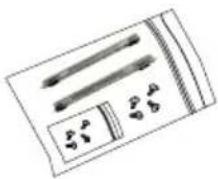
(10) HDD holder (screws are included)
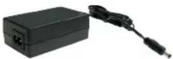
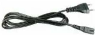
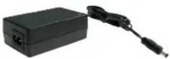
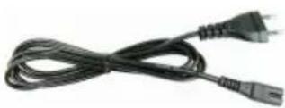
(11) Power adaptor
(12) Power cord( **The power cord varies depending on the standard power outlet of the country where it is sold)

If there is any damage, shortage or inappropriate item in the package contents, please contact with local dealer
Hardware Installation
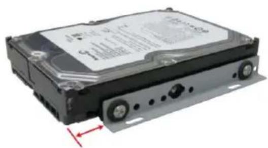
C. Install the hard disk
Follow the below steps to install the hard disk:
- Loosen all screws
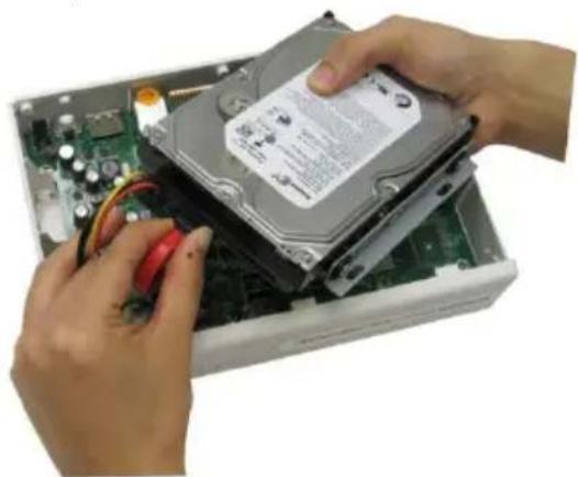
- Secure the HDD holder on the hard disk. The position to screw the HDD holder on hard disk must same as figure shown. Otherwise, the hard disk won't be able to fit into inside the DVR unit.
natural_image
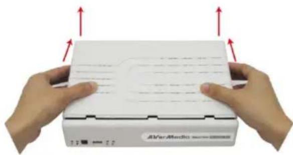
Exterior view of a hard disk drive (no visible text or labels)- Push the cover backward and lift
natural_image
Close-up of hands holding a white electronic device with red arrows indicating upward motion (no text or symbols visible)- Connect the end of the SATA cable and the power connector to the hard disk
natural_image
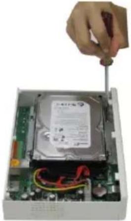
Close-up of hands installing a hard disk into an open computer chassis (no visible text or symbols)- Secure the hard disk inside the unit then place unit cover
natural_image
Hand inserting a screwdriver into a computer hard drive module (no visible text or symbols)- Push the cover forward and secure the cover
natural_image
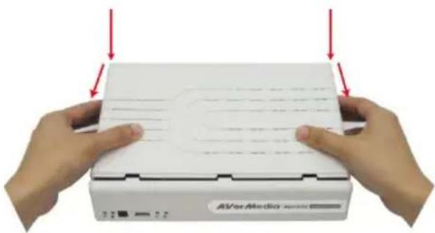
Close-up of hands holding a white electronic device with red arrows pointing to the top panel (no visible text or symbols on the device itself)- You may now connect all the cables. When the power is connected, the Power LED light

turns on
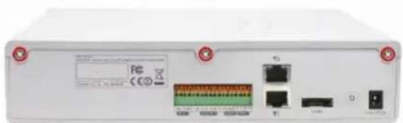
D. Device Connection
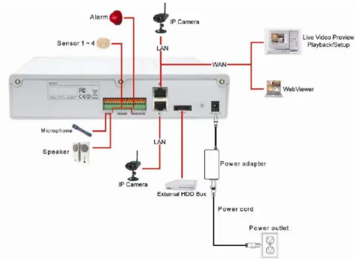
The back panel of the DVR unit, user can connect the 4 sensor devices, 1 alarm device, audio input/output device and an external HDD storage device. Through the dual Gigabit LAN ports can balance the network bandwidth on the IP camera connection and preview live video.
Follow the illustration below to make the connection:
flowchart
graph TD
    A["Sensor 1~4"] --> B["IP Camera"]
    B --> C["LAN"]
    C --> D["WAN"]
    D --> E["Live Video Preview Playback/Setup"]
    E --> F["WebViewer"]
    G["Microphone"] --> H["IP Camera"]
    I["Speaker"] --> J["IP Camera"]
    K["External HDD Box"] --> L["Power adapter"]
    M["Power cord"] --> N["Power outlet"]
    O["Alarm"] --> P["IP Camera"]
    Q["LAN"] --> R["LAN"]
    S["LAN"] --> T["LAN"]

- The number of the cameras connection that depends on the DVR model user has purchased.
LUPUSNET LE900: 4 cameras
LUPUSNET LE908: 8 cameras
- The port LAN 1 that is located at lower position is only configurable for Fixed IP of the network mode.
- Port LAN2 is configurable for PPPOE, DHCP, or Fixed IP of the network mode.
V. System Requirement
| Motherboard Motherboard with Intel 915 / 945 / 955 / 965 / 975 / P35 / P45 chipset and NVIDIA nForceTM4 Ultra MCP , nVidia nForce 570 SLI chipset | |
| CPU Pentium® 4 3.2 GHz or higherDual core CPU is highly recommended | |
| Hard disk 120GB or higher | |
| OS Windows XP Professional / Windows Vista / Windows 7 | |
| RAM 1GB or higher | |
| VGA card | 32-bit high color SVGA graphics card with 128MB video memory and DirectDraw® / YUV Rendering Capability |
| Ethernet 10/100/1000 Base-T Ethernet card | |
| Others Sound card and speakers | |
VI. Install the MXR Client Software
- Make sure the PC is connecting to your network.
- Place the software CD into DVD-COM/CD-ROM drive on your PC.
- Click Install MXR Client Software to install. And then, follow the on screen instruction to complete the installation.
- After computer restarted, you may now run the MXR Client Software. To run the application, click on your PC desktop or click Start > Programs > DVR > DVR Server > MXR.

- MXR Client Software only can be installed and run on the PC that is using independent graphic card.
- T he DVR server does not support the remote setup through the Internet (WAN) for the first time setup. Please have your PC and the DVR server at same LAN segme (network).
VII. Connect a DVR Server for Monitoring
- The default IP of the DVR server is 192.168.2.2 for LAN1 (lower LAN port in the back of the DVR) or 192.168.3.2 for LAN2 (upper LAN port in the back of the DVR).

- The port LAN 1 that is located at lower position is only configurable for Fixed IP of the network mode.
- Port LAN2 is configurable for PPPOE, DHCP, or Fixed IP of the network mode.

Please make sure DVR server and your PC is connected in the same physical network in order for search function can work correctly.
-
Run the MXR Client Software on your PC. To run the application, click on your PC desktop or click Start > Programs > DVR > DVR Server > MXR.
-
Enter the ID and Password(default is superuser/111111) to login the MXR Client application.
-
Click Setup (Setup) from MXR Client application interface. Enter the ID and Password (default is superuser/111111). And then, select Client Setup mode. The System Setting window will show up.
-
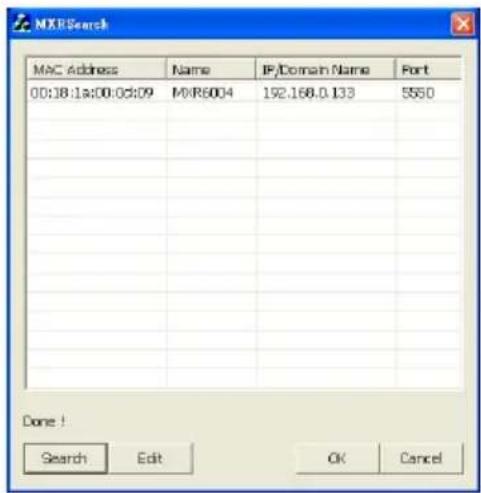
Click Add, and then, click Search to find the DVR server that you have installed on your network.
-
Select the DVR server that you want to configure from the search result list and click OK.
-
If user wants to change the IP of the DVR, select the DVR in MXR Search windows and click Edit.
-
In MXR Setting windows, user can change Name of the DVR, connection Port, Network mode (Static IP/DHCP), IP, Mask, Gateway, and DNS.

- The Name, Port, Network, IP, Mask, and Gateway are required to enter.
- The Port LAN 1 only supports Static IP.
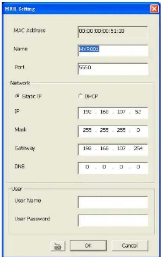
- Enter the User Name and Password for changing authentication. And then, click OK to complete the change.

The User Name and User Password is the DVR system login ID and password (default is superuser/111111).
-
After changed the DVR data, click Search to re-find the DVR server again.
-
Select the DVR server from search result list in MXR Search window and click OK.
-
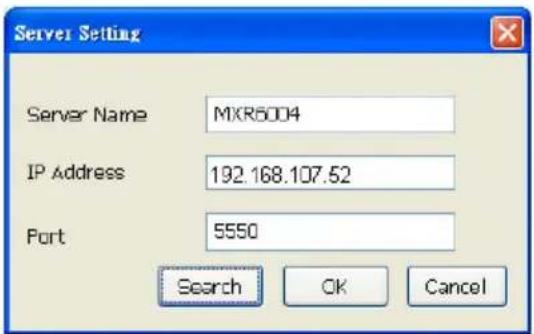
The new DVR information will display in Server Setting window. Click OK to add the DVR server.
-
When the DVR server has been added, click OK to exit the System Setting window.
-
And then, click (Network) to connect with the DVR server.
VIII. Connect an IP Camera
-
Click Setup (Setup) from surveillance application interface. Enter the ID and Password (default is superuser/111111). In Mode Select dialog, select Server Setup and click OK.
-
Select the Camera. The Camera setting window will show up.
-
Select camera icon and enable the camera
-
Select IP Camera in Input section. Mark Display to show the video of the camera on the screen. Mark Audio to enable the audio of the camera to be recorded.
-
Enter the Name and Description of the camera.
-
Click IP Setting in IP Camera Information section. Enable Protocol, and then, select Protocol, Mode, Video Format, Channel, and IP Camera Site of the IP camera.
-
Instead enter IP address of the IP camera; user also can enter URL of the IP camera.
-
Enable Authentication, and then, enter ID and password if IP camera's access authority is
required.
- Click OK to complete the setting.
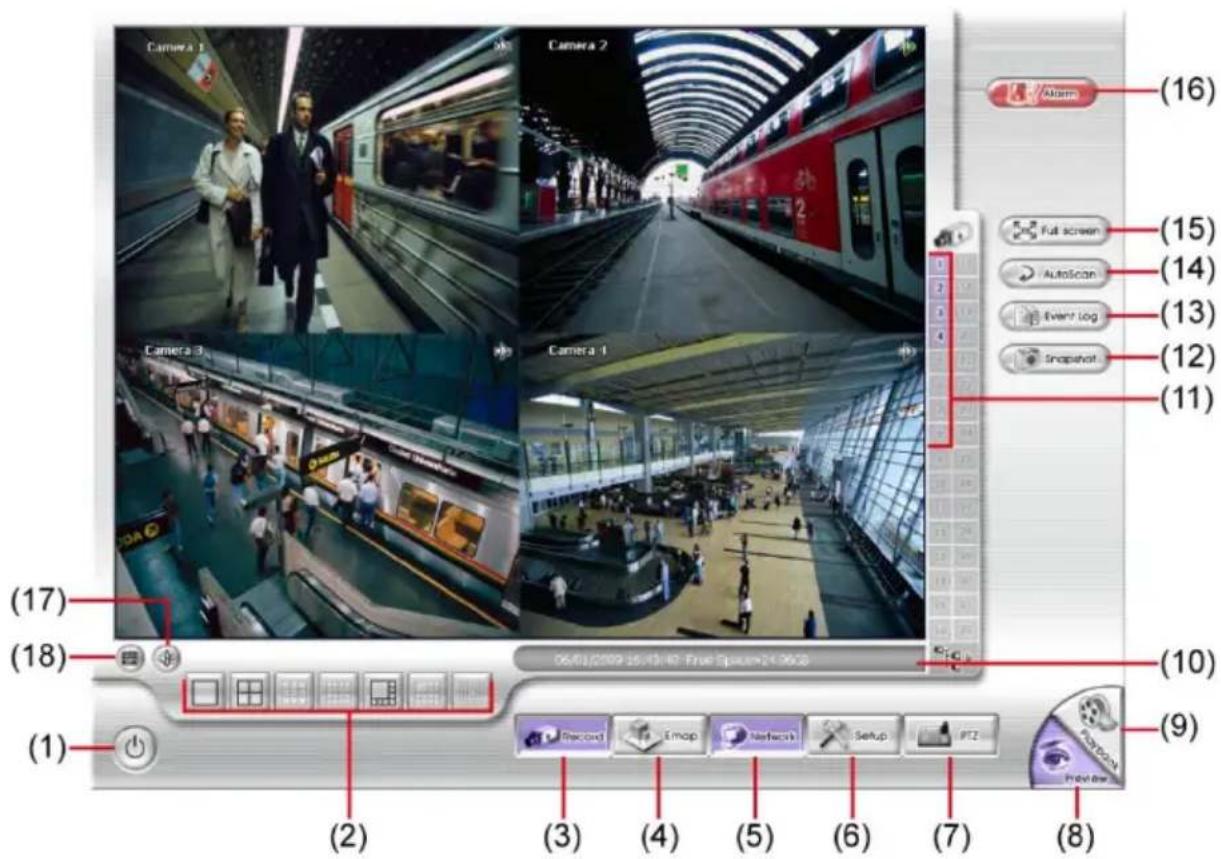
Familiarizing the Buttons in Preview Mode
In the logout dialog box, you may do the following:
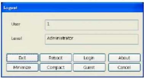
- Exit: To close the application
- Reboot: To restart the DVR system. It is required to enter the password.
- Login: Using different ID to login to DVR system.
- About: Display product information.
- Minimize: To reduce the DVR to taskbar button.
- Compact: To switch to compact mode.
- Guest: To switch to the guest mode. In guest mode, the functions are limited to preview function only. For complete functions of DVR, please login as an administrator.
- Cancel: To exit Logout dialog box.
(2) Split Screen Mode Select from 3 different split screen types to view all the camera, or one camera over the other or alongside on a single screen. It also allows you to switch and view different camera number.

- When you are in single screen mode, Right click and Drag a square on the area you want to enlarge.
- DVR system doesn't support partial enlarge in full screen mode.
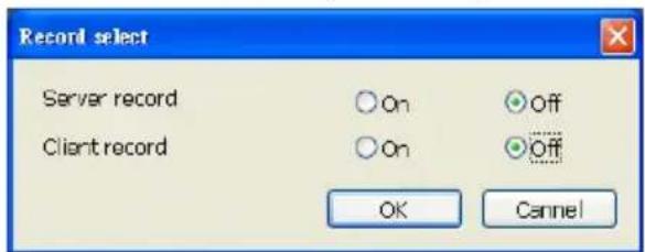
(3) Record Start/stop server and client site video recording.
- Server record: Start/stop recording at MXR DVR server.
- Client record: Start/stop recording at remote client site.
(4) EMap Display the map in each area, and the location of camera/ sensor/ relay and the warning.
(5) Network Enable/disable remote system access. This feature allows you to access DVR server from a remote location via internet connection. The default is disabled.
(6) Setup Configure the system settings.
Name Function
| (7) PTZ Access PTZ control panel. | |
| (8) Preview Switch to Preview mode. This allows you to view live camera display. | |
| (9) Playback Switch to Playback mode. This allows you to view the recorded video file. | |
| (10) Status bar Display the recoding date, time and hard disk space of DVR unit. | |
| (11) Camera ID | Show the number of cameras that are being viewed. When you are in single screen mode, click the camera ID number to switch and view other camera. |
| (12) Snapshot Capture and save the screen shot in *.jpg format. | |
| (13) Event log Show the record of activities that take place in the system. | |
| (14) AutoScan | Start/Stop video screen cycle switch. |
| (15) Full screen | View in full screen. To return, press the right button of the mouse or ESC on the keyboard or click the arrow icon. When you switch to full screen in multiple-screen mode, Left click to toggle to only display one of the video in the multiple-screen mode or all. |
| (16) Alarm Alert and display warning info. | |
| (17) Virtual Keyboard If the keyboard is not available, you may use the Virtual Keyboard. | |
| (18) Audio | Enable/disable audio. User can click the audio icon on the channel to switch the different channel's volume play. When audio icon is green, it means the channel audio is playing now. |
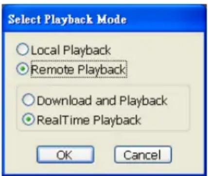
To Playback the Recorded Video
To switch in Playback mode, click Playback button at the lower right corner of Preview mode user interface.
In the Select Playback Mode dialog box, select Local Playback if user has enabled the client record. Select the RealTime Playback if your internet bandwidth is fast and big enough otherwise choose Download and Playback. Click OK to proceed and Cancel to void this operation.
Playback in Local Playback Mode
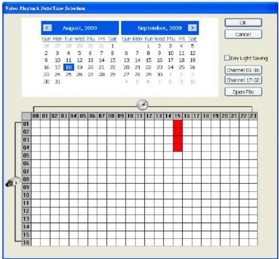
When selected the Local Playback mode, select the date and time to playback from the Video Playback Date/Time Selection. In the Video Playback Date/Time Selection, the number from 00 to 23 represent the time in 24-hour clock. The numbers from 01 to 16 represent the camera number.
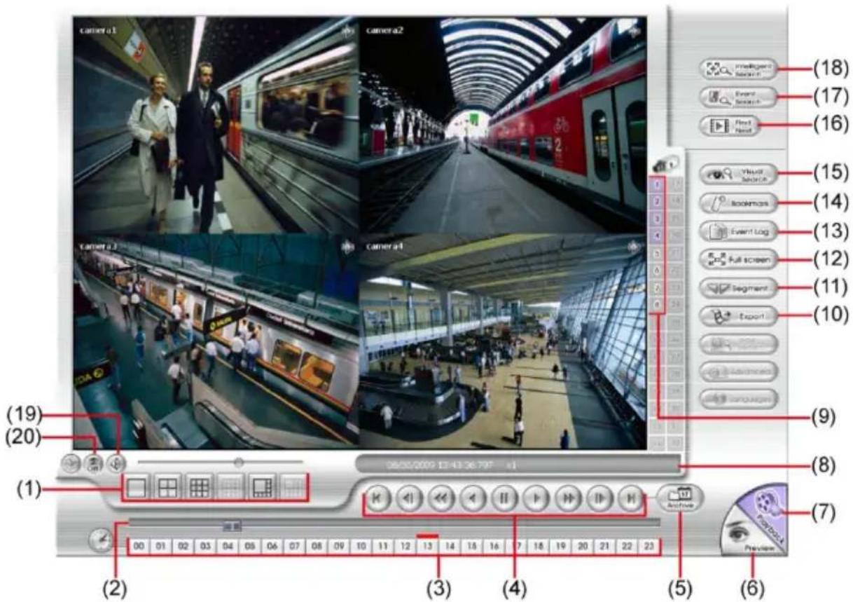
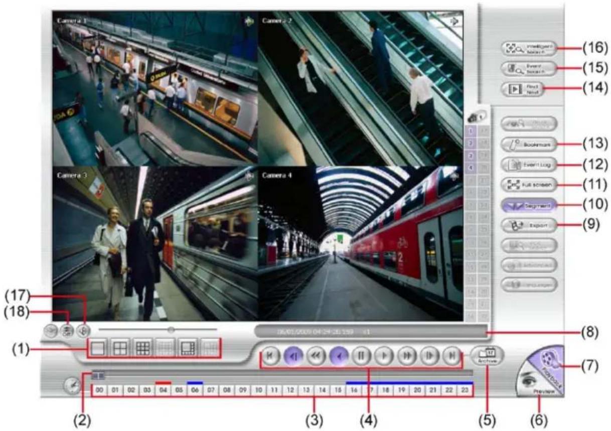
The Local Playback interface as following shown:
Name Function
(1) Split Screen Mode Select from 4 different split screen type to playback the recorded video file of all the camera, or one camera.

To zoom in an area on the screen, Right click and Drag a square on the area you want to enlarge.
(2) Progress bar Show the progress of the file being played. You may move the bar to seek at any location of the track.
(3) Hour Buttons Select and click to playback the recorded video file on the specific time frame.

The Hour buttons represent the time in 24-hour clock. The blue bar on top of the hour button indicates that there is a recorded video file on that period of time. While the red bar indicates that you are currently viewing the recorded video file.
| Name Function | |
| (4) Playback Control Buttons | Begin: Move at the beginning of the recorded video file.Previous: Go back to the previous frame.Slower: Play the recorded video file at the speed of 1/2x, 1/4x, or 1/8x.Rewind: Wind back the recorded video file.Pause: Briefly stop playing the recorded video file.Play: Play the recorded video file. |
| (4) Playback Control Buttons | Faster: Play the recorded video file at the speed of 2x, 4x, or 8x, 16x or 32x.Next: Go to the next frame.End: Go to the end of the recorded video file. |
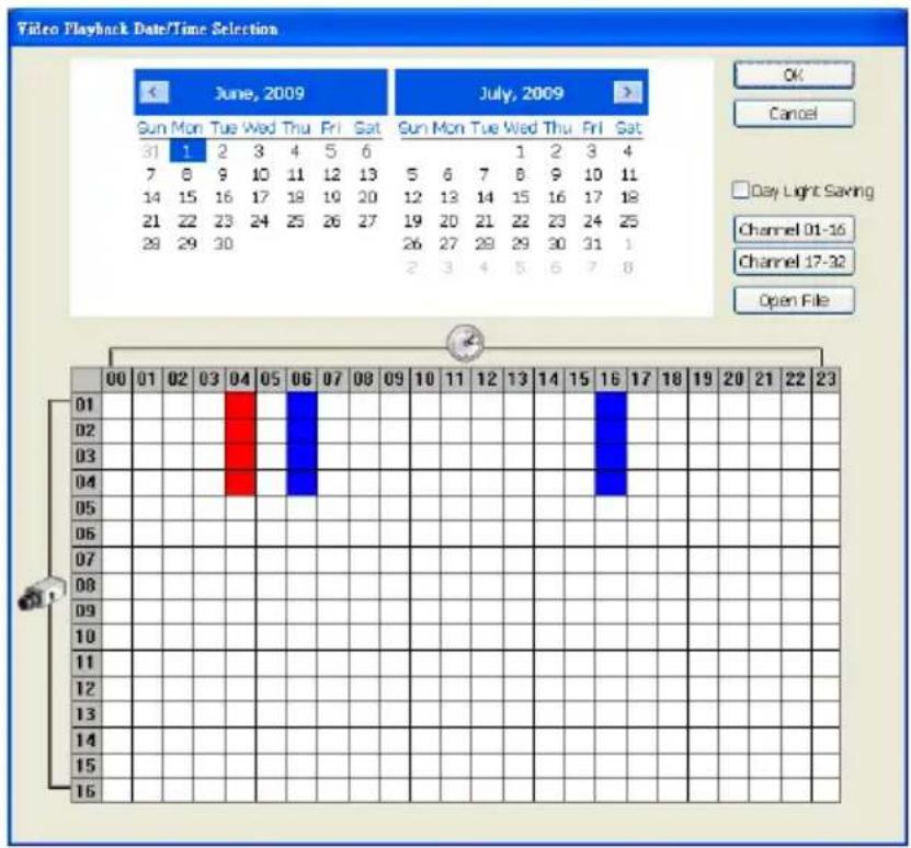
| (5) Archive | - Select the date on the calendar and the time from 00 to 23 to where to start playing the recorded video file.- Also, user can open the recorded file from certain location by click OPEN FILE button- Mark Day Light Saving, the playback calendar will show the available playback records during day light saving period.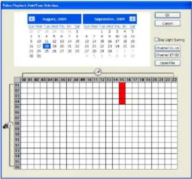 |

- Channel 01-16 and Channel 17-32 button doesn't have function because the MXR DVR only supports 4 channels.
- The numbers from 00 to 23 represent the time in 24-hour clock. The numbers from 01 to 16 represent the camera ID. The blue colored column indicates that there is a recorded video file on that period of time. While the red colored column indicates on
Name Function
where to start playing the recorded video file.
| (6) Preview | Switch to Preview/Advanced mode. |
| (7) Playback | Switch to Playback mode. This allows you to view the recorded video file. |
| (8) Status bar Display the recorded date, time and play speed. | |
| (9) Camera ID | Show the number of cameras that are being viewed. When you are in single screen mode, click the camera ID number to switch and view other camera. |
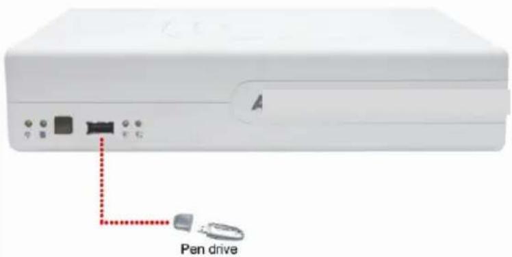
(10) Export Export includes Snapshot, Print, Output Video Clip, and Backup function.
■ Snapshot: Capture and save the screen shot either in *.jpg or *.bmp format.
■ Print: Print the screen shot.
■ Output Video Clip: Save the segmented file in *.mpg, *.avi, or *.dvr format.
■ Backup: Save the playback file to USB device or DVD disk
(11) Segment Keep a portion of the recorded video.
(12) Full screen View in Playback-compact mode. To return, press the right button of the mouse or ESC on the keyboard. When you switch to full screen in multiple-screen mode, Left click to toggle to only display one of the video in the multiple-screen mode or all.
(13) Event log Show the record of activities that take place in the system. To filter the records, select and click the option button to only display Event,
Name Function
| System, Operation, Network or POS. | |
| (14) Bookmark | Mark a reference point when previewing the recorded video file to which you may return for later reference. You may also set it to protect the file. |
| (15) Visual Search | Search from a specific camera by Date, Hour, Minute, 10 Seconds and Second. |
| (16) Find Next | Search for the next event or changes in the motion detector frame. You can use this when you are using Intelligent Search or Event Search function. |
| (17) Event Search Search from the recorded activities that take place in the system (i.e., Sensor, Motion, Video Loss, POS). | |
| (18) Intelligent Search | Search the changes in the motion detector frame. |
| (19) Audio | Enable/disable audio play |
| (20) De-interlace | To enhance the video quality. Set the de-interlace mode to #1, if you are capturing motionless picture and #2, if it captures lots of movement. |
Playback in Download and Playback Mode
When selected the Download and Playback mode, select the date and time to playback from the Remote Playback Date/Time Selection. In the Remote Playback Date/Time Selection, the number from 00 to 23 represent the time in 24-hour clock. The numbers from 01 to 16 represent the camera number.
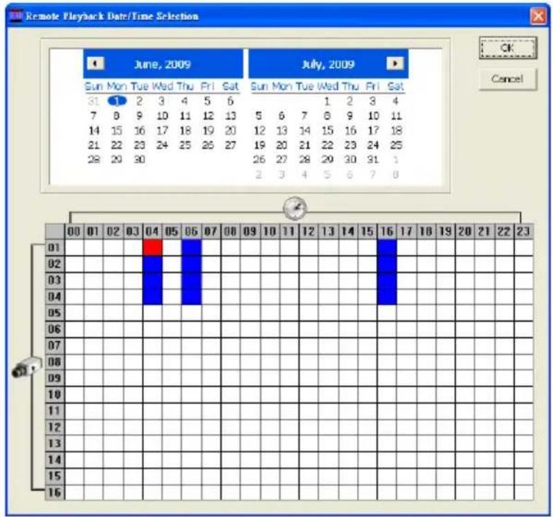
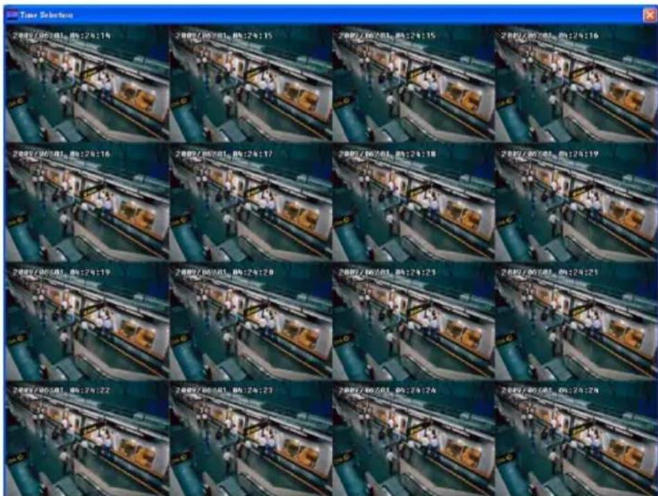
Click OK and the Time Selection window will show up. In Time Selection window, the system divides the selected hour into 16 video thumbnails. Click on the video thumbnail you want to download and open.
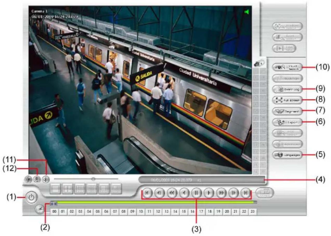
The Download and Playback interface as following shown:
Name Function
(1) Exit To exit application
(2) Progress bar Show the progress of the file being played. You may move the bar to seek at any location of the track.
Name Function
(3) Playback Control Buttons

Begin: Move at the beginning of the recorded video file.

Previous: Go back to the previous frame.

Slower: Play the recorded video file at the speed of 1/2x, 1/4x, or 1/8x.

Rewind: Wind back the recorded video file.

Pause: Briefly stop playing the recorded video file.

Play: Play the recorded video file.

Faster: Play the recorded video file at the speed of 2x, 4x, or 8x, 16x or 32x.

Next: Go to the next frame.

End: Go to the end of the recorded video file.
(4) Status bar Display the recorded date, time and play speed.
(5) Language To switch the application tips' display language
(6) Export Export includes Snapshot, Print, and Output Video Clip function.
■ Snapshot: Capture and save the screen shot either in *.jpg or *.bmp format.
■ Print: Print the screen shot.
■ Output Video Clip: Save the segmented file in *.mpg, *.avi, or *.dvr format
(7) Segment Keep a portion of the recorded video.
(8) Full screen View in Playback-compact mode. To return, press the right button of the mouse or ESC on the keyboard.
When you switch to full screen in multiple-screen mode, Left click to toggle to only display one of the video in the multiple-screen mode or all.
(9) Event log Show the record of activities that take place in the system. To filter the records, select and click the option button to only display Event, System, Operation, Network or POS.
(10) Visual Search Search from a specific camera by Date, Hour, Minute, 10 Seconds
Name Function
and Second.
(11) Audio Enable/disable audio play
(12) De-interlace To enhance the video quality. Set the de-interlace mode to #1, if you are capturing motionless picture and #2, if it captures lots of movement.
Playback in RealTime Playback Mode
When selected the RealTime Playback mode, select the date and time to playback from the Video Playback Date/Time Selection. In the Video Playback Date/Time Selection, the number from 00 to 23 represent the time in 24-hour clock. The numbers from 01 to 16 represent the camera number. Mark Day Light Saving, the playback calendar will show the available video records during day light saving time period.
Click OK and the RealTime Playback interface as following shown:
Name Function
(1) Split Screen Mode Select from 3 different split screen type to playback the recorded video file of all the cameras or one camera.

To zoom in an area on the screen, Right click and Drag a square on the area you want to enlarge.
(2) Progress bar Show the progress of the file being played. You may move the bar to seek at any location of the track.
(3) Hour Buttons Select and click to playback the recorded video file on the specific time frame.

The Hour buttons represent the time in 24-hour clock. The blue bar on top of the hour button indicates that there is a recorded video file on that period of time. While the red bar indicates that you are currently viewing the recorded video file.
(4) Playback Control Buttons
Begin: Move at the beginning of the recorded video file.
Previous: Go back to the previous frame.
Slower: Play the recorded video file at the speed of 1/2x, 1/4x, or 1/8x.
Rewind: Wind back the recorded video file.
Pause: Briefly stop playing the recorded video file.
Play: Play the recorded video file.
Faster: Play the recorded video file at the speed of 2x, 4x, or 8x, 16x or 32x.
Next: Go to the next frame.
End: Go to the end of the recorded video file.
(5) Archive - Select the date on the calendar and the time from 00 to 23 to where to start playing the recorded video file. - Also, user can open the recorded file from certain location by click OPEN FILE button - Mark Day Light Saving, the playback calendar will show the available playback records during day light saving period.
Name Function

The numbers from 00 to 23 represent the time in 24-hour clock. The numbers from 01 to 16 represent the camera ID. The blue colored column indicates that there is a recorded video file on that period of time. While the red colored column indicates on where to start playing the recorded video file.
(6) Preview Switch to Preview/Advanced mode.
(7) Playback Switch to Playback mode. This allows you to view the recorded video file.
(8) Status bar Display the recorded date, time and play speed.
(9) Camera ID Show the number of cameras that are being viewed. When you are in single screen mode, click the camera ID number to switch and view other camera.
(10) Export Export includes Snapshot, Print, and Output Video Clip function.
■ Snapshot: Capture and save the screen shot either in *.jpg or *.bmp format.
■ Print: Print the screen shot.
■ Output Video Clip: Save the segmented file in *.mpg, *.avi, or *.dvr format.
(11) Segment Keep a portion of the recorded video.
(12) Full screen View in Playback-compact mode. To return, press the right button of the mouse or ESC on the keyboard.
When you switch to full screen in multiple-screen mode, Left click to toggle to only display one of the video in the multiple-screen mode or all.
(13) Event log Show the record of activities that take place in the system. To filter the records, select and click the option button to only display Event, System, Operation, Network or POS.
(14) Bookmark Mark a reference point when previewing the recorded video file to which you may return for later reference. You may also set it to protect
Name Function
| the file. |
| (15) Find Next Search for the next event or changes in the motion detector frame. You can use this when you are using Intelligent Search or Event Search function. |
| (16) Event Search Search from the recorded activities that take place in the system (i.e., Sensor, Motion, Video Loss, POS). |
| (17) Intelligent Search Search the changes in the motion detector frame. |
| (18) Audio Enable/disable audio play |
| (19) De-interlace To enhance the video quality. Set the de-interlace mode to #1, if you are capturing motionless picture and #2, if it captures lots of movement. |
LUPUS-Electronics® GmbH
Lise-Meitner-Str.20, D-76829 Landau
Tel. +49 (0) 6341 93 55 3 0 Fax. +49 (0) 6341 93 55 3 20