GEODOME LE335 - Security Camera Lupus Electronics - Free user manual and instructions
Find the device manual for free GEODOME LE335 Lupus Electronics in PDF.

| Product Type | Security Camera |
| Brand | Lupus Electronics |
| Model | GEODOME LE335 |
| Category | Dome Security Camera |
| Dimensions (W x H x D) | Approx. 110 x 90 x 110 mm |
| Weight | Approx. 400 g |
| Power Supply | 12V DC or PoE (Power over Ethernet) |
| Resolution | 3 MP (2048 x 1536) |
| Lens | 2.8 mm fixed lens, 90° field of view |
| Night Vision | Built-in IR LEDs, up to 20 m range |
| Weatherproof Rating | IP66 (outdoor rated) |
| Audio | Built-in microphone (one-way audio) |
| Storage | MicroSD card slot (max 128 GB) or NVR |
| Video Compression | H.265 / H.264 |
| Motion Detection | Yes, with configurable sensitivity |
| Mobile App Support | LupusNet or compatible ONVIF apps |
| Operating Temperature | -20°C to 50°C |
| Mounting | Ceiling or wall mountable |
| Maintenance | Wipe with a soft dry cloth; avoid solvents |
| Safety Certifications | CE, RoHS |
| Spare Parts | Mounting bracket, screws, power adapter (optional) |
| Repairability | Not user-serviceable; contact support |
| Warranty | 2 years |
| General Information | Manual available in PDF format |
Frequently Asked Questions - GEODOME LE335 Lupus Electronics
User questions about GEODOME LE335 Lupus Electronics
0 question about this device. Answer the ones you know or ask your own.
Ask a new question about this device
Download the instructions for your Security Camera in PDF format for free! Find your manual GEODOME LE335 - Lupus Electronics and take your electronic device back in hand. On this page are published all the documents necessary for the use of your device. GEODOME LE335 by Lupus Electronics.
USER MANUAL GEODOME LE335 Lupus Electronics
natural_image
Close-up of a LUPUS security camera with visible lens and control panel (no text or symbols on body)Benutzerhandbuch
User Manual
Inhalt
- Einführung....3
- Hinweise....3
2.1 Warnungen:....4
2.2 Hinweise zur Benutzung und Installation: 4
3 Beschreibung: 5
4 Highlights: 5 - Lieferumfang: 7
5.1 Beschreibung der einzelnen Bauteile 8 - Installation 9
7.1 Das OSD MENU 13
7.2 OSD HAUPTMENU....14
7.2.1 LENS: MANUAL/AUTO....14
7.2.2 SHUTTER/AGC: AUTO / MANUAL....14
7.2.3 WHITE BAL 15
7.2.4 BACKLIGHT: BLC / HLC / OFF....16
7.2.5 ATR: ON / OFF....16
7.2.6 DNR: 16
7.2.7 PICT ADJUST: 16
7.2.8 NEXT:....17
7.2.9 EXIT:....17
7.2.10 SAVE ALL:....17
7.2.11 DAY/NIGHT : AUTO / DAY / B/W....17
7.2.12 PRIVACY: ON/OFF....18
7.2.13 MOTION: ON / OFF....19
7.2.14 CAMERA ID: ON / OFF....20
7.2.15 SPRACHE 20
7.2.16 CAMERA RESET 20
7.2.17 BACK....20 - Technische Daten ....21
1. Einführung
Adaptive Tone Reproduction (ATR)
High Light Compensation (HLC)
■ 3-Axis Movement for Free Lens Rotation
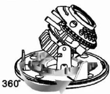
natural_image
Mechanical assembly diagram showing a gear and housing component, labeled 360° (no text or symbols beyond label)Horizontal Rotation
Tilt Rotation
natural_image
Mechanical assembly diagram showing a rotating component with 120° label (no readable text or symbols)Pan Rotation
natural_image
Cross-sectional diagram of a security camera module with rotating arrows indicating rotation (no text or symbols)natural_image
Cross-sectional diagram of a security camera with rotating base and sensor array (no text or symbols)6. Kamerasicherung
natural_image
Technical line drawing of a security camera module with mounting holes and a sensor array (no text or symbols)7. Anschluss
natural_image
Pure electrical circuit lines without any symbols7.1 Das OSD MENU
| OSD Setup Menu page 1 | |
| LENS | AUTO |
| SHUTTER/ AGC | AUTO |
| WHITE BAL | ATW |
| BACKLIGHT | OFF |
| ATR | OFF |
| NR | |
| PICT ADJUST | |
| NEXT | |
| EXIT SAVE ALL | |
| OSD Setup Menu page 2 | |
| DAY/ NIGHT | AUTO* |
| PRIVACY | OFF |
| MOTION DET | OFF |
| CAMERA ID | OFF |
| LANGUAGE | ENGLISH |
| CAMERA RESET | |
| BACK↓ | |
| EXIT ↓ SAVE ALL | |
● SHUTTER/AGC: MANUAL
| MANUAL | MODE : SHUT+AGC |
| SHUTTER :NTSC : 1/60, 1/100, 1/250, 1/500, 1/1000, 1/2000, 1/4000, 1/10000PAL : 1/50, 1/120, 1/250, 1/500, 1/1000, 1/2000, 1/4000, 1/10000 | |
| AGC : 6.00、12.00、18.00、24.00、30.00、36.00、42.00、44.80 |
natural_image
Close-up of a LUPUS surveillance camera with lens and control panel (no visible text or symbols beyond branding)User Manual
Inhalt
- INTRODUCTION....3
- USAGE AND INSTALLATION NOTE.... 3
- FEATURES 5
- PACKING LIST 6
- NAME and FUNCTION of EACH PART 7
- INSTALLATION 8
6.1 Camera Installation & Operation 8
- OPERATION 12
7.1 OSD Framework 12
7.2 OSD Main Menu Description....13
7.2.1 LENS: MANUAL /AUTO selectable.... 13
7.2.2 SHUTTER/AGC: AUTO / MANUAL selectable. 13
7.2.3 WHITE BAL 14
ATW / PUSH / USER1 / USER2 / ANTI CR / MANUAL / PUSH LOCK selectable. 14
7.2.4 BACKLIGHT: BLC / HLC / OFF selectable.... 15
7.2.5 ATR: ON / OFF selectable.... 15
7.2.6 NR: ↩ 15
7.2.7 PICT ADJUST: ← 15
7.2.8 NEXT: 17
7.2.9 EXIT: ← 17
7.2.10 SAVE ALL: 17
7.2.11 DAY/NIGHT : AUTO / DAY / B/W selectable.... 17
7.2.12 PRIVACY: ON / OFF selectable. 18
7.2.13 MOTION: ON / OFF selectable. 19
7.2.14 CAMERA ID: ON / OFF selectable....20
7.2.15 LANGUAGE....20
7.2.16 CAMERA RESET 20
7.2.17 BACK....20
- SPECIFICATION 20
1. INTRODUCTION
Thank you for your purchase of your brand new GEODOME®-LE335 Camera. Please read the manual carefully before the first activation and keep it at a safe place for further usage. The documentation, images and technical specifications are subject to change. The camera is suitable for both in- and outdoor use.
2. USAGE AND INSTALLATION NOTE
IMPORTANT NOTICE


It is vital to comply with the safety instructions before and while using this GEODOME camera. If you are unable to install the device yourself, please seek help from a professional installer.
Please read the manual carefully before the first activation and keep it at a safe place for further usage or in case of giving the device to third persons.

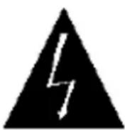
The flash symbol in a triangle indicates danger of electric shock. Never open camera housing or the housing of the supplied power adapter.
WARNING:
TO REDUCE THE RISK OF ELECTRIC SHOCK, DO NOT CARRY OUT INSTALLATION OUTDOORS UNDER WET CONDITIONS. THE INSTALLATION OF THE DEVICE SHALL ONLY BE CARRIED OUT BY QUALIFIED PERSONNEL.
This camera is a weather proof high quality video surveillance camera. Please note the following safety instructions:
- Do not focus the camera to the sun.
- Do not focus the camera to a spotlight.
- Handle the camera carefully and protect it from strong vibrations or hits.
- Do not touch internal components or wiring
- Do not install the camera close to strong electrical currents which could undermine its image quality.
- Do not attach the camera to an aluminium or iron surface without insulating it from the surface.
• Always comply with max. humidity and temperature conditions. - This device must not be operated by persons with physical, sensorical or mental disabilities or persons with limited experience or knowledge unless these persons are supervised by a person specifically assigned to care for their safety. The devise shall under no circumstances be operated by children.
- The camera contains wiring which may lead to strangulation or small items which may be swallowed. Please keep the camera, its packaging and associated items away from children.
In case of malfunction
In case of malfunction, please pull the powerplug and contact your dealer. Further usage may increase the risk of fire or electric shock.
Intended usage
The camera is intended for conventional video surveillance by day and night. It is designed for both in- and outdoor use. Please make sure that privacy rights of third persons be not infringed at any time. The surveillance of persons without their explicit knowledge and consent is prohibited by law in many countries.
This product must not be used for any other purpose save those set out in the user manual. Contravention may lead to loss of warranty and guarantee as well as the exclusion of liability. This includes changes to and modifications of the product.

Orderly disposal:
Do not dispose of this product with your domestic waste!
This device complies with the EU regulation on electronic waste and therefore must not be disposed of with domestic waste. Please dispose of this product with your local waste disposal for electronic devices.
3. FEATURES
Clear image quality has been achieved by employing a 1/3" Hi-Res. CCD, which provides a horizontal resolution of 650 TV lines. The camera can be by External Light Sensor; it provides Color image in full light condition (Day) and provides B/W image in low light condition (Night) to reach the best effect. High performance: providing unique ATR (Adaptive Tone Reproduction), DNR (Digital Noise Reduction), HLC (High Light Compensation), CRS (Color Rolling Support), Privacy function, Mirror function, as well as manually adjusting picture quality functions (Such as Contrast/Sharpness/Color etc.).
High Resolution
CCD Sensor provides high resolution reaching 650\~700 TVL with advanced and clear picture quality.
Adaptive Tone Reproduction (ATR)
ATR is the Single Scan WDR function; it has the other name with Digital WDR, Software WDR. perfectly shows the image details between dark and light. Newly added environment dynamic detection switch, enhancing WDR image efficiency.
Day & Night
Mechanic IR Cut-Filter driving unit with Light Sensor.
Privacy Mask
Privacy image masking with free position, support up to 8 areas of privacy masking zone.
Lens (External manual focus)
Built-in DC-type Vari-Focal lens with ICR / Without ICR.
Excellent Sensitivity
High sensitivity, low smear, high anti-blooming and high S/N ratio.
Digital Noise Reduction (DNR)
With 2DNR enable, it can reduce the noise to produce extremely clear picture quality even under low light condition.
High Light Compensation (HLC)
By setting mask are, the user will experience better operation convenience see a clearer image.
Motion Detection
Camera-site takes the initiative in providing motion detection alert for a more comprehensive monitoring and careful editing of motion detection area. When there are changes within the detection area, the camera immediately issues a warning.
OSD
OSD (On Screen Display) Setup Menu. Camera tile setup of up to 16 alphanumeric letters.
Mechanism
Weatherproofing Housing Design.
Application
All function can be operated from OSD: AES (Automatic Electronic Shutter), AI (Auto Iris), GC (Gain Control), WB (White Balance), BLC (Back Light compensation), positive/ negative and Horizontal Mirror.
4. PACKING LIST
Check to make sure all of the items shown below are included in your product package. If something is missing, contact your dealer as soon as possible.
| Item Description | Item Picture | QTY |
| Camera & Bracket | 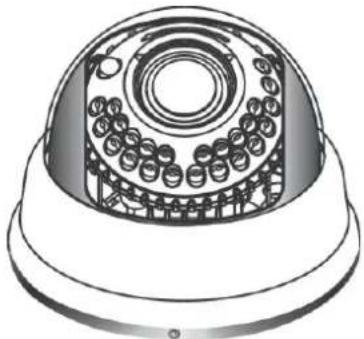 | 1 |
| Appurtenances |  | 1 |
| Fix retaining screw |  | 4 |
| Countersunk Head Screws for Camera Protection | [774V] | 1 |
| Instruction Manual 1 |
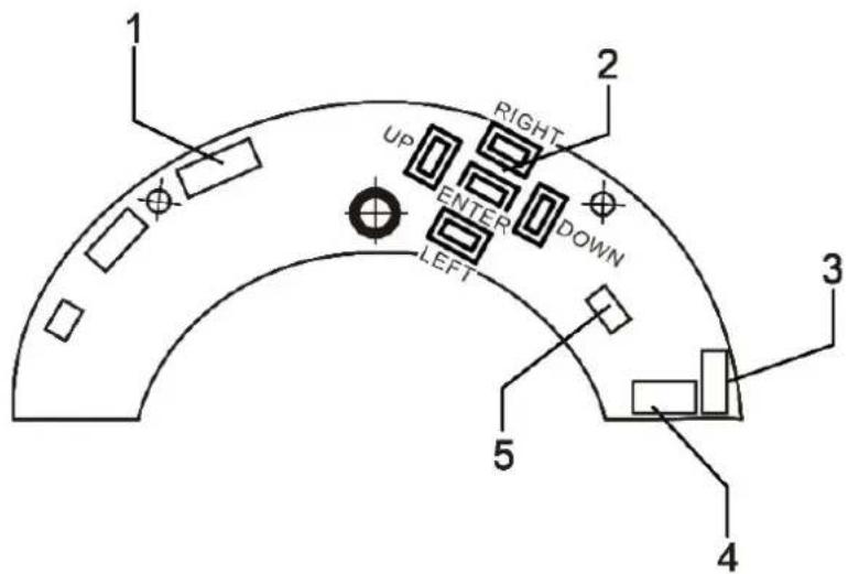
5. NAME and FUNCTION of EACH PART
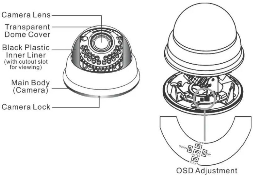
To adjust the OSD, remove the dome cover from the main body by gently turning the cover counter-clockwise to unlock and pull free from the main body. The OSD buttons are can be found on the main body of the dome camera.
1\~3.OSD Button (Menu):
| No. | Name | Function |
| 1 | LEFT LEFT | |
| 2 | ENTER Get in MENU and ENTER | |
| 3 | DOWN DOWN | |
| 4 | RIGHT RIGHT | |
| 5 | UP UP |
6. INSTALLATION
6.1 Camera Installation & Operation
1. Removing the Dome Cover
Remove the dome cover from the main body by gently turning the cover counter-clockwise to unlock and pull free from the main body.
2. Camera Image Adjustment
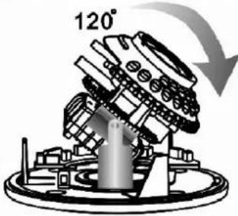
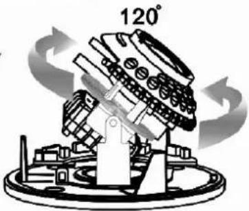
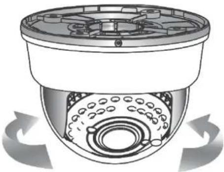
- You can adjust camera to any direction by using Pan, Tilt, and Rotate mechanism.
- Pan Base moves by 60^ to each side direction and 120^ on the whole.
- Tilt Base covers total 120^ angle (60° to each side).
• Angle range of Rotate Base is 360^ .
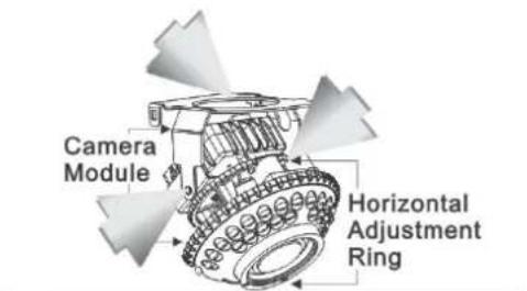
Auto Iris Lens or with IR LED
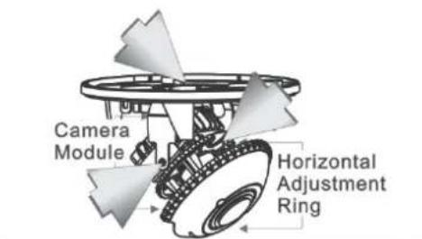
Auto Iris Lens without IR LED
or Fix Iris Lens without IR LED
■ 3-Axis Movement for Free Lens Rotation
natural_image
Mechanical assembly diagram showing a rotating component with a 360° angle indicator (no text or symbols on the diagram itself)Horizontal Rotation
Tilt Rotation
natural_image
Mechanical component diagram showing a rotating assembly with 120° label (no readable text or symbols)Pan Rotation
3. Adjusting the Vari-Focal Lens
- Loosen the Zoom lever counter-clockwise a little, and then rotate the Zoom lever to obtain the best image view.
- Loosen the Focus lever counter-clockwise a little, and then rotate the Focus lever to obtain the optimum picture quality.
• Re-tighten the Zoom lever and Focus lever after adjustment.
- Adjusting the Function Control Board
1
IR BOARD WEFER
3
POWER/VIDEO (CAMERA)
5 DAY IN
2 OSD KEY 4
POWER/VIDEO (DC/BNC)
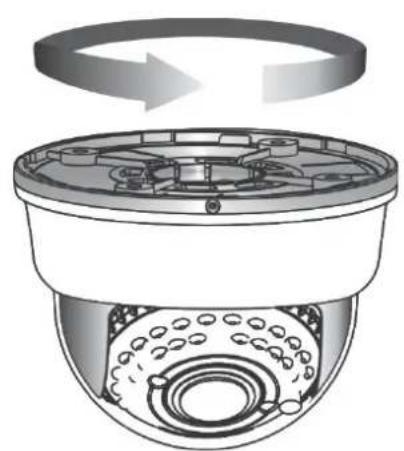
5. Attaching the Dome Cover
- After all necessary adjustment has been made reinstall the dome cover to the main body.
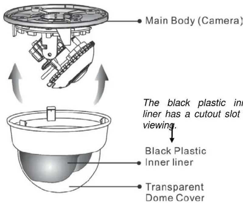
- Reinstall the dome cover and the main body by turning the dome clockwise until it locks in place.
natural_image
Diagram of a surveillance camera with rotating top panel and sensor array (no text or symbols)- The dome comes with a black plastic inner liner placed within the dome cover. Therefore, after replacing the dome cover rotate the liner so that the cutout slot (hole for viewing) is in the correct position and not blocking the camera lens.
natural_image
Cross-sectional diagram of a security camera with rotating base and sensor array (no text or symbols)6. Camera Protection
To prevent unpredictable damage and burglary, lock-up the dome by using the countersunk head screw.
natural_image
Technical illustration of a surveillance camera with internal components and a sensor array (no text or symbols)7. Wiring Instructions
Connect the video output to the monitor or other video device through a 75 Ohms type coaxial cable and the DC-Jack or AC/ DC-Terminator to the power source.
7. OPERATION
7.1 OSD Framework
Main Menu Display
| OSD Setup Menu page 1 | |
| LENS | AUTO← |
| SHUTTER/ AGC | AUTO← |
| WHITE BAL | ATW |
| BACKLIGHT | OFF |
| ATR | OFF |
| NR | ← |
| PICT ADJUST | ← |
| NEXT← | |
| EXIT← SAVE ALL | |
| OSD Setup Menu page 2 | |
| DAY/ NIGHT | AUTO* |
| PRIVACY | OFF |
| MOTION DET | OFF |
| CAMERA ID | OFF |
| LANGUAGE | ENGLISH |
| CAMERA RESET | |
| BACK← | |
| EXIT← SAVE ALL | |
Main Menu Setup
- In order to display the setup menu on the screen, set the menu command or press the button panel.
- Use UP/ DOWN control buttons to select each item.
- Use LEFT/ RIGHT control buttons to change the data.
- Use MENU control button to ENTER/ EXIT the menu display.
- ←=ENTER
*NOTE: LE335 is comming without IR-LED's
7.2 OSD Main Menu Description
7.2.1 LENS: MANUAL /AUTO selectable.
LENS: MAUNAL
Not adjustment
LENS: AUTO
OPEN: Lens fully open.
CLOSE: Lens fully closed.
SPEED: Speed of the lens.
7.2.2 SHUTTER/AGC: AUTO / MANUAL selectable.
- SHUTTER/AGC: AUTO
| AUTO | HIGH LUMINANCE |
| MODE : SHUT+AUTO IRIS / AUTO IRIS / SHUTBRIGHTNESS : 000~255 | |
| LOW LUMINANCEMODE : AGC / OFFBRIGHTNESS : x0.25、x0.50、x0.75、x1.00 |
HIGH LUMINANCE
When LENS is setup to AUTO mode
SHUT+AUTO IRIS: Exposure is controlled by auto electronic shutter combined with auto iris.
AUTO IRIS: Exposure controlled by auto iris.
When LENS is setup to Manual mode
SHUT: Exposure controlled by electronic shutter.
LOW LUMINANCE
Setup low lux environment, minimum AGC level.
● SHUTTER/AGC: MANUAL
| MANUAL | MODE : SHUT+AGC |
| SHUTTER :NTSC : 1/60, 1/100, 1/250, 1/500, 1/1000, 1/2000, 1/4000, 1/10000PAL : 1/50, 1/120, 1/250, 1/500, 1/1000, 1/2000, 1/4000, 1/10000 | |
| AGC : 6.00、12.00、18.00、24.00、30.00、36.00、42.00、.80 |
SHUTTER: Fixed electronic shutter speed.
AGC: Fixed AGC gain control.
7.2.3 WHITE BAL
ATW / PUSH / USER1 / USER2 / ANTI CR / MANUAL / PUSH LOCK selectable.
● WHITE BAL.: ATW
| ATW | SPEED : 000~255 |
| DELAY CNT : 000~255 | |
| ATW FRAME : x0.50、x1.00、x1.50、x2.00 | |
| ENVIRONMENT : INDOOR、OUTDOOR |
SPEED : ATW Speed
DELAY CNT : ATW Delay Time
ATW FRAME : ATW Frame Range Setup
ENVIRONMENT ATW Environment Range Setup
● WHITE BAL.: PUSH
The function will keep detecting the Color Temperature, and then it will keep saving the parameter to camera.
● WHITE BAL.: USER1
| USER1 | B-GAIN :000~255 |
| R-GAIN :000~255 |
● WHITE BAL.: USER2
| USER2 | B-GAIN :000~255 |
| R-GAIN :000~255 |
● WHITE BAL.: MANUAL
The function can reduce the color rolling issue, and it is the same with CRS (Color Rolling Support) function.
● WHITE BAL.: PUSH LOCK
The function will detect the Color Temperature to save into the camera.
7.2.4 BACKLIGHT: BLC / HLC / OFF selectable.
- BACKLIGHT.: BLC
Enable the function of Back Light Compensation, and the detection method is the BLC Smart.
- BACKLIGHT.: HLC
Enable the function of High Light Compensation.
7.2.5 ATR: ON / OFF selectable.
- ATR.: ON
NR MODE : Set the DNR mode of Y/C, Y and C.
Y LEVEL : Set the Y filter strength.
C LEVEL : Set the C filter strength.
NOTE: The Y/C mode is the automatic DNR mode.
7.2.7 PICT ADJUST:
| MIRROR | ON / OFF |
| BRIGHTNESS | 000~255 |
| CONTRAST | 000~255 |
| SHARPNESS | 000~255 |
| HUE 000~255 | |
| GAIN 000~255 |
Adjust all camera parameters here.
7.2.8 NEXT:
Move to MAIN MENU, page 2
7.2.9 EXIT: ←
Exit OSD to choose the list.
7.2.10 SAVE ALL:
When you change the OSD menu settings, before leaving the OSD item option SAVE ALL. Press ENTER key to change the memory settings for the OSD.
7.2.11 DAY/NIGHT : AUTO / DAY / B/W selectable.
DAY/NIGHT: AUTO
DELAY CNT : Set the Night/ Day identification transfer time.
DAY→ NIGHT : Set the threshold for identifying the Night status from the Day status.
NIGHT → DAY : Set the threshold for identifying the Day status from the Night status.
● DAY/NIGHT: DAY Day mode forcibly
● DAY/NIGHT: NIGHT Night mode forcibly
| Night | BURST : ON/OFF |
BURST : Selects whether to output the burst signal
7.2.12 PRIVACY: ON / OFF selectable.
PRIVACY: ON
| AREA SEL Max. 8 | |
| TOP 000~244 (NTSC) / 000~288(PAL) | |
| BOTTOM | 000~244 (NTSC) / 000~288(PAL) |
| LEFT | 550TVL : 000~378(NTSC)、000~370 (PAL)650TVL : 000~474 (NTSC)、000~468 (PAL) |
| RIGHT | 550TVL : 000~378 (NTSC)、000~370 (PAL)650TVL : 000~474 (NTSC)、000~468 (PAL) |
| COLOR 1~8 | |
| TRANSP 0.00 / 0.50 / 0.75 / 1.00 | |
| MOSAIC ON / OFF | |
AREA SEL : Select the mask frame to be adjusted.
NOTE: When the MONITOR AREA has been set to ON by the MOTION DET setting, only 4 PRIVACY AREA SEL are selectable (1 / 4, 2 / 4, 3 / 4, 4 / 4).
TOP : Set the top side of the mask frame selected
BOTTOM : Set the bottom side of the mask frame selected
LEFT : Set the left side of the mask frame selected
RIGHT : Set the right side of the mask frame selected
COLOR : Set the colors of the mask frames.
TRANSP : Set the transparency ratio of the mask frames.
MOSAIC : Set the mask frame mosaic function to ON or OFF.
7.2.13 MOTION: ON / OFF selectable.
● MOTION DET: ON
| DETECT SENSE 000~127 | |
| BLOCK DISP | ON / OFF / ENABLE |
| MONITOR AREA ON / OFF | |
| AREA SEL 1~4 | |
| TOP 000~244 (NTSC) / 000~288(PAL) | |
| BOTTOM | 000~244 (NTSC) / 000~288(PAL) |
| LEFT | 550TVL : 000~378 (NTSC)、000~370 (PAL)650TVL : 000~474 (NTSC)、000~468 (PAL) |
| RIGHT | 550TVL : 000~378 (NTSC)、000~370 (PAL)650TVL : 000~474 (NTSC)、000~468 (PAL) |
DETECT SENSE: Set the motion detection sensitivity.
BLOCK DISP: Control the ON/ OFF status of the motion detection block display.
MONITOR AREA: Set whether to use the monitoring frames.
AREA SEL: Select the monitoring frame to be set.
TOP: Set the top side of the monitoring frame selected
BOTTOM: Set the bottom side of the monitoring frame selected
LEFT: Set the left side of the monitoring frame selected
RIGHT: Set the right side of the monitoring frame selected
7.2.14 CAMERA ID: ON / OFF selectable.
| ABCDEFGHIJKLMNOPQRSTUVWXYZ0123456789-!"#$%&'()_' ¥: ;<=>?@\^*.x+/ | Each User Font |
| ←→↑↓ | The camera ID cursor moves in the direction of the arrow when the Enter operation input is performed from the status in which ←, →, ↑ or ↓ has been selected using the character selection cursor. |
| CLR | The character selected by the camera ID cursor is cleared when the Enter operation input is performed from the status in which CLR has been selected using the character selection cursor. |
| POS | The display switches to the camera ID display position setting screen when the Enter operation input is performed from the status in which POS has been selected using the character selection cursor. On the camera ID display position setting screen, the camera ID display position is changed in real time in response to the left, right, up or down operation input. When the Enter operation input is performed, the display position is entered, and the display returns to the camera ID setting screen. |
7.2.15 LANGUAGE
There are 8 kind of language: English / Japanese / German / French / Russian / Portuguese / Spanish / Simplified Chinese selectable.
7.2.16 CAMERA RESET
Reset Factory default setup.
7.2.17 BACK
Return to MAIN MENU, page1.
8. SPECIFICATION
| Image Device | 1/3" Color CCD Ex-View HAD II (Sony Chipset) | ||
| Effective Picture Elements | NTSC: 976x494PAL: 976x582 | ||
| Horizontal Resolution | Day: 650 TVLNight: 700 TVL | ||
| Minimum Illumination | 0.01ux/ F1.2 (Day) | ||
| Day to Night Illumination | Under 5 Lux | ||
| S/N Ratio | More than 48dB (AGC OFF) | ||
| Shutter Speed Control | NTSC:1/60~1/100,000, PAL:1/50~1/100,000 | ||
| Lens Furnished | Vari-Focal Lens and Vari-Focal Lens with ICR | ||
| Auto Iris Control DC Driver | |||
| Gain Control Auto/ Manual | |||
| White Balance | ATW / PUSH / USER1 / USER2 / ANTI CR / Manual / PUSH LOCK | ||
| ATR ON/ OFF | |||
| DNR | ON/ OFF | ||
| Back Light Compensation | ON/ OFF | ||
| High Light Compensation | ON/ OFF | ||
| PRIVACY Maximum 8 Areas | |||
| MOTION DET | 4 Areas | ||
| Camera ID | Up to 52 Characters | ||
| Mirror ON/ OFF | |||
| Positive/ Negative | ON/OFF | ||
| Video Output | 1Vp-p/ 75 Ohms | ||
| Power Supply | DC 12V±10% | ||
| Power Consumption | Vari-Focal Lens | 120mA max. | |
| Vari-Focal Lens+IR | IR On | 370mA max. | |
| IR Off 120mA max. | |||
| Operating Temp. | -10°C ~ 50 °C (14 to 122°F) | ||
| Gamma Characteristic | 0.45 | ||
| Synchronous System | INT | ||
| Dimensions (WxD) | 32 mm x32 mm (Camera board)37 mm x35 mm (OSD board) | ||
LUPUS-Electronics® GmbH
Lise-Meitner-Str.20, D-76829 Landau
Tel. +49 (0) 6341 93 55 3 0 Fax. +49 (0) 6341 93 55 3 20