WVCL930 - Surveillance Camera PANASONIC - Free user manual and instructions
Find the device manual for free WVCL930 PANASONIC in PDF.

User questions about WVCL930 PANASONIC
0 question about this device. Answer the ones you know or ask your own.
Ask a new question about this device
Download the instructions for your Surveillance Camera in PDF format for free! Find your manual WVCL930 - PANASONIC and take your electronic device back in hand. On this page are published all the documents necessary for the use of your device. WVCL930 by PANASONIC.
USER MANUAL WVCL930 PANASONIC
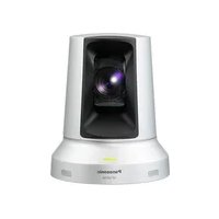
Color CCTV Cameras Operating Instructions
Model Nos. WV-CL930 WV-CL934
(Lens: option)
Before attempting to connect or operate this product, please read these instructions carefully and save this manual for future use.
No model number suffix is shown in this manual.
ENGLISH VERSION
WARNING:
- This apparatus must be earthed.
- Apparatus shall be connected to a mains socket outlet with a protective earthing connection.
- The mains plug or an appliance coupler shall remain readily operable.
- To prevent fire or electric shock hazard, do not expose this apparatus to rain or moisture.
- The apparatus should not be exposed to dripping or splashing and that no objects filled with liquids, such as vases, should be placed on the apparatus.
- All work related to the installation of this product should be made by qualified service personnel or system installers.
- The connections should comply with local electrical code.
CAUTION
RISK OF ELECTRIC SHOCK DO NOT OPEN

CAUTION: TO REDUCE THE RISK OF ELECTRIC SHOCK, DO NOT REMOVE COVER (OR BACK). NO USER-SERVICEABLE PARTS INSIDE. REFER SERVICING TO QUALIFIED SERVICE PERSONNEL
The lightning flash with arrowhead symbol, within an equilateral triangle, is intended to alert the user to the presence of uninsulated "dangerous voltage" within the product's enclosure that may be of sufficient magnitude to constitute a risk of electric shock to persons.

The exclamation point within an equilateral triangle is intended to alert the user to the presence of important operating and maintenance (servicing) instructions in the literature accompanying the appliance.
Power disconnection. Unit with or without ON-OFF switches have power supplied to the unit whenever the power cord is inserted into the power source; however, the unit is operational only when the ON-OFF switch is in the ON position. Unplug the power cord to disconnect the main power for all units.
For Canada
This Class A digital apparatus complies with Canadian ICES-003.
For U.S.A
NOTE: This equipment has been tested and found to comply with the limits for a Class A digital device, pursuant to Part 15 of the FCC Rules. These limits are designed to provide reasonable protection against harmful interference when the equipment is operated in a commercial environment. This equipment generates, uses, and can radiate radio frequency energy and, if not installed and used in accordance with the instruction manual, may cause harmful interference to radio communications.
Operation of this equipment in a residential area is likely to cause harmful interference in which case the user will be required to correct the interference at his own expense.
FCC Caution: To assure continued compliance, (example - use only shielded interface cables when connecting to computer or peripheral devices). Any changes or modifications not expressly approved by the party responsible for compliance could void the user's authority to operate this equipment.
For U.S.A
The serial number of this product may be found on the surface of the unit.
You should note the model number and serial number of this unit in the space provided and retain this book as a permanent record of your purchase to aid identification in the event of theft.
Model No.
Serial No.
CONTENTS
Important Safety Instructions 4
Limitation of Liability 5
Disclaimer of Warranty 5
Preface 6
Precautions 7
Major Operating Controls and Their
Functions 9
■Side view 9
■Rear view 9
Installations/Connections 11
Optional dedicated lens 11
Setting of external synchronization switch 18
External terminal 18
Setup Menu 19
Setup menu list 19
■Basic operation 21
Camera Operation Setup [CAMERA
SETUP] 23
1. Camera title setting [CAMERA ID] 23
2.Method of controlling quantity of light [ALC/ELC] 25
Backlight compensation 25
3. Electronic shutter setting [SHUTTER] 28
4. Gain control setting [AGC] 29
5. Electronic sensitivity enhancement setting [SENS UP] 30
6. Synchronization setting [SYNC] 31
7. White balance setting [WHITE BAL] .... 35
8. Motion detector function setting [MOTION DET] 36
- Digital noise reduction function setting [DNR] 40
- Image resolution setting [RESOLUTION] 40
- Settings in black-and-white mode [BW MODE] 40
- Privacy zone setting [PRIVACY ZONE] 42
- Image horizontal flip [MIRROR] 43
- Lens type setting [LENS-DRIVE] 43
- Image stabilizer setting [STABILIZER] 44
Back focus setting [BACK-FOCUS
SETUP] 45
Special Menu Setup [SPECIAL SETUP] ... 47 Chroma level adjustment
[CHROMAGAIN] 47
Aperture level adjustment [AP GAIN] 47
Pedestal level adjustment [PEDESTAL] .. 47 Chroma phase level (hue)
adjustment [HUE] 48
Pixel compensation [PIX OFF] 48
Communication configuration [COMMUNICATION] 49
Default restoring [CAMERA RESET] 49
Serial number viewing [SER.NO.] 49
Language Selection [LANGUAGE SETUP] 50
Shortcut Operation 51
Troubleshooting 52
Specifications 54
Standard Accessories 55
Important Safety Instructions
1) Read these instructions.
2) Keep these instructions.
3) Heed all warnings.
4) Follow all instructions.
5) Do not use this apparatus near water.
6) Clean only with dry cloth.
7) Do not block any ventilation openings. Install in accordance with the manufacturer's instructions.
8) Do not install near any heat sources such as radiators, heat registers, stoves, or other apparatus (including amplifiers) that produce heat.
9) Do not defeat the safety purpose of the polarized or grounding-type plug. A polarized plug has two blades with one wider than the other. A grounding type plug has two blades and a third grounding prong. The wide blade or the third prong are provided for your safety. If the provided plug does not fit into your outlet, consult an electrician for replacement of the obsolete outlet.
10) Protect the power cord from being walked on or pinched particularly at plugs, convenience receptacles, and the point where they exit from the apparatus.
11) Only use attachments/accessories specified by the manufacturer.
12) Use only with the cart, stand, tripod, bracket, or table specified by the manufacturer, or sold with the apparatus. When a cart is used, use caution when moving the cart/apparatus combination to avoid injury from tip-over.

13) Unplug this apparatus during lightning storms or when unused for long periods of time.
14) Refer all servicing to qualified service personnel. Servicing is required when the apparatus has been damaged in any way, such as power-supply cord or plug is damaged, liquid has been spilled or objects have fallen into the apparatus, the apparatus has been exposed to rain or moisture, does not operate normally, or has been dropped.
Limitation of Liability
THIS PUBLICATION IS PROVIDED "AS IS" WITHOUT WARRANTY OF ANY KIND, EITHER EXPRESS OR IMPLIED, INCLUDING BUT NOT LIMITED TO, THE IMPLIED WARRANTY OF MERCHANTABILITY, FITNESS FOR ANY PARTICULAR PURPOSE, OR NON-INFRINGEMENT OF THE THIRD PARTY'S RIGHT.
THIS PUBLICATION COULD INCLUDE TECHNICAL INACCURACIES OR TYPOGRAPHICAL ERRORS. CHANGES ARE ADDED TO THE INFORMATION HEREIN, AT ANY TIME, FOR THE IMPROVEMENTS OF THIS PUBLICATION AND/OR THE CORRESPONDING PRODUCT (S).
Disclaimer of Warranty
IN NO EVENT SHALL Panasonic Corporation BE LIABLE TO ANY PARTY OR ANY PERSON, EXCEPT FOR REPLACEMENT OR REASONABLE MAINTENANCE OF THE PRODUCT, FOR THE CASES, INCLUDING BUT NOT LIMITED TO BELOW:
(1) ANY DAMAGE AND LOSS, INCLUDING WITHOUT LIMITATION, DIRECT OR INDIRECT, SPECIAL, CONSEQUENTIAL OR EXEMPLARY, ARISING OUT OF OR RELATING TO THE PRODUCT;
(2) PERSONAL INJURY OR ANY DAMAGE CAUSED BY INAPPROPRIATE USE OR NEGLIGENT OPERATION OF THE USER;
(3) UNAUTHORIZED DISASSE REPAIR OR MODIFICATION OF THE PRODUCT BY THE USER;
(4) INCONVENIENCE OR ANY LOSS ARISING WHEN IMAGES ARE NOT DISPLAYED, DUE TO ANY REASON OR CAUSE INCLUDING ANY FAILURE OR PROBLEM OF THE PRODUCT;
(5) ANY PROBLEM, CONSEQUENTIAL INCONVENIENCE, OR LOSS OR DAMAGE, ARISING OUT OF THE SYSTEM COMBINED BY THE DEVICES OF THIRD PARTY;
(6) ANY CLAIM OR ACTION FOR DAMAGES, BROUGHT BY ANY PERSON OR ORGANIZATION BEING A PHOTOGENIC SUBJECT, DUE TO VIOLATION OF PRIVACY WITH THE RESULT OF THAT SURVEILLANCE-CAMERA'S PICTURE, INCLUDING SAVED DATA, FOR SOME REASON, BECOMES PUBLIC OR IS USED FOR THE PURPOSE OTHER LE, THAN SURVEILLANCE.
Preface
This product is a 1/2-inch type 1 / 2" CCD color CCTV camera. Connection of this product to a video monitor allows users to use this product as a monitoring camera. The main features are described as follows:
Introduction of near-infrared CCD
This camera has the capacity to shoot pictures under the light source from the near-infrared light region to the visible light region.
Auto back focus function (ABF) equipped
Moving the CCD inside the camera to an optimal position with the operation button of this unit or the setup menu allows users to automatically adjust the back focus.
The back focus is adjustable with the setup menu through the system controller (option) even after installation of this unit.
The auto back focus function also allows users to correct out of focus when changing between color and black-and-white images.
High sensitivity achieved thanks to noise reduction function
As low as 0.09 lx (F1.4) has been accomplished for color images thanks to the introduction of low noise circuit design.
Night monochrome image activation function equipped
No setting change is required at night because images automatically changes from the color mode to the black-and-white mode at low illuminance.
Motion detector function equipped
If motion is observed in the monitor, the camera is covered with a cloth, a cap, or the like, or the camera direction is changed during monitoring, an alarm signal is provided.
Note:
- The motion detector function is not exclusively used for prevention of theft, fire, etc. We are not responsible for any accidents or damages occurring in case.
Precautions
This product has no power switch.
Power is supplied from an external 12 V DC/ 24 V AC (WV-CL934) or 120 V AC (WV-CL930) power-supply device. Refer to service personnel for how to turn on/off the power.
To keep on using with stable performance
- Parts of this product may deteriorate and it may shorten lifetime of this product when using in locations subject to high temperatures and high humidity. Do not expose this product to direct heat sources such as a heater.
- Use the product at temperature within -10^ to +50^ (14°F to 122°F) and humidity below 90% . (When using this product without turning the power off)
Do not rub the edges of metal parts with your hand.
Failure to observe this may cause injury.
Do not attempt to disassemble this product.
To prevent electric shock, do not remove screws or covers.
There are no user-serviceable parts inside. Ask qualified service personnel for servicing.
Use this product for indoor use only.
Do not expose this product to direct sunlight for hours and do not install the product near a heater or an air conditioner. Otherwise, it may cause deformation, discoloration and malfunction. Keep this product away from water.
Handle this product with care.
Do not abuse this product. Avoid striking, shaking, etc. The product could be damaged by improper handling or storage.
Cleaning this product body
Turn the power off when cleaning this product. Use a dry cloth to clean this product. Do not use strong abrasive detergent when cleaning this product. When the dirt is hard to remove, use a mild detergent and wipe gently. Then, wipe off the remaining detergent with a dry cloth.
Otherwise, it may cause discoloration. When using a chemical cloth for cleaning, read the caution provided with the chemical cloth product.
Noise on monitor
This product is equipped with a super sensitive CCD. Therefore, white dot noise may appear on the monitor. This phenomenon is not trouble.
Discoloration on the CCD color filter
When continuously shooting a bright light source such as a spotlight, the color filter of the CCD may have deteriorated and it may cause discoloration. Even when changing the fixed shooting direction after continuously shooting a spotlight for a certain period, the discoloration may remain.
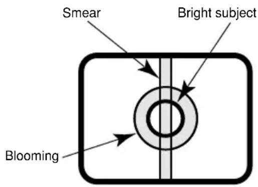
Do not aim this product at strong light sources.
A light source such as a spot light causes a blooming (light bleeding) or a smear (vertical lines).
Turn the circuit breaker off which supplies this product with the power when abnormal conditions are encountered.
Avoid installing in the following locations.
- Locations where it may get wet from rain or water splash
- Locations where a chemical agent is used such as a swimming pool (not only outdoor)
- Locations subject to steam and oil smoke such as a kitchen
- Locations near flammable gas or vapor
- Locations where radiation or x-ray emissions are produced
- Locations subject to strong magnetic field or radio waves
- Locations where corrosive gas is produced
- Locations where it may be damaged by briny air such as seashores
- Locations where the temperature is not within -10^ to +50^ {14°F to 122°F}.
- Locations subject to vibrations (This product is not designed for on-vehicle use.)
- Locations subject to condensation as the result of severe changes in temperature
Installing place
Contact your dealer for assistance if you are unsure of an appropriate place in your particular environment.
Make sure that the installation area is strong enough to hold this product, such as a concrete ceiling.
Do not install this product in a humid or dust-laden environment.
Otherwise, lifetime of the internal parts may be shortened.
Be sure to remove this product if it is not in use.
Radio interference
When this product is used near TV/radio antenna, strong electric field or magnetic field (near a motor or a transformer), images
may be distorted and noise sound may be produced.
Mounting screws
Only the fixing screws are provided to fix this product with the camera mounting base. It is necessary to procure screws or bolts to mount this product. Prepare them according to the material and strength of the area where this product is to be installed. The screws and bolts must be tightened with an appropriate tightening torque according to the material and strength of the installation area.
Do not operate this product beyond the specified temperature, humidity or power source ratings.
Use this product at temperatures within -10^ to +50^ {14 F to 122 F}, and humidity below 90% . The input power source is 12 V DC/24 V AC (WV-CL934) or 120 V AC (WV-CL930).
Avoid connections during a lightning storm.
Otherwise, an electric shock may be caused.
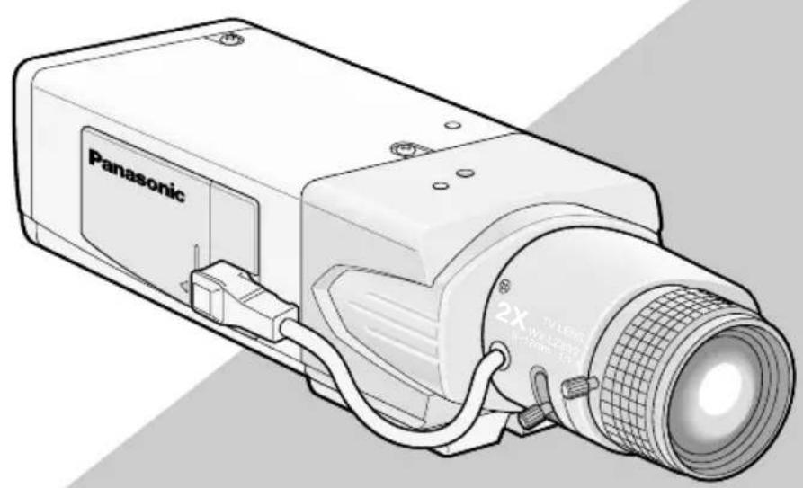
Major Operating Controls and Their Functions
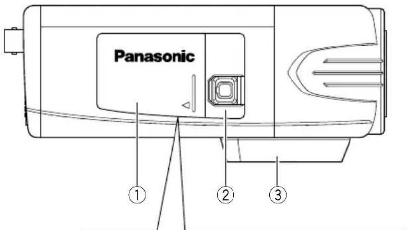
Side view
WV-CL930/WV-CL934>
Inside the side cover
(Slide the cover leftward to the lock position.)
Rear view
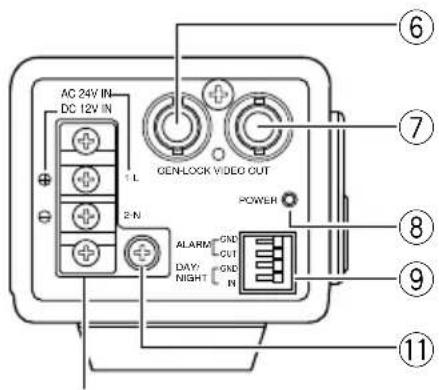
WV-CL934>
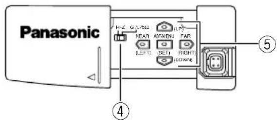
①Side cover
When the external synchronization switch or operation buttons are used, the side cover is slid leftward to the lock position.
② ALC lens connector
The ALC connector is connected to this ALC lens connector. If the connector shape is a different type, replace the connector with the ALC connector (accessory).
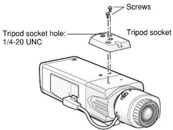
③ Tripod socket
This socket is used to mount the camera mounting base (option). The tripod socket can be mounted on either top or bottom of the camera head.
(Tripod socket hole: 1/4-20 UNC for tripod)
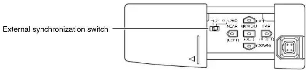
④ External synchronization switch
page 18)
⑤Operation buttons
This buttons are used to perform various settings in the setup menu.
Up button (UP)
Down button (DOWN)
: Left button (LEFT), NEAR
: Right button (RIGHT), FAR
: Setting button (SET), ABF/MENU
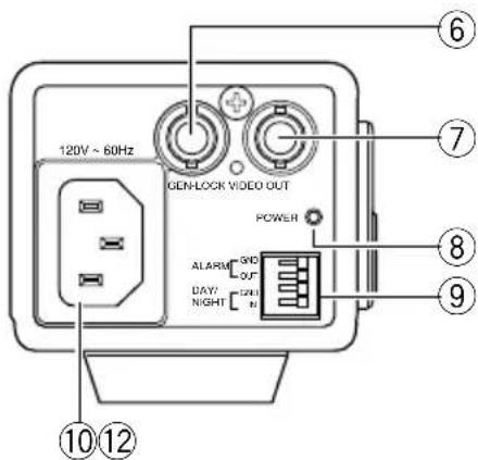
⑥ External synchronization input connector
page 14)
⑦Video output connector
The video output cable is connected to this video output connector.
⑧Power indicator
This indicator lights up when the power is on.
External terminal
page 18)
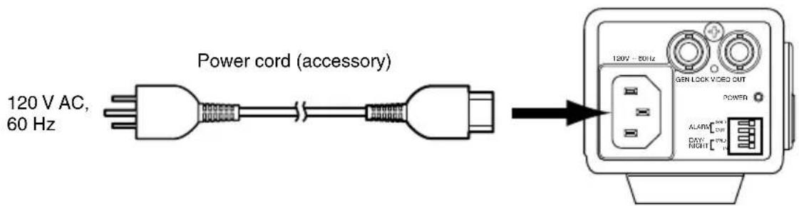
⑩ Power connector (only for WV-CL930)
The included power cord is connected to this power connector.
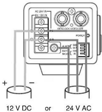
① Signal ground terminal (only for WV-CL934)
The ground wire is connected to this terminal.
② AC/DC power terminal (only for WV-CL934)
The power supply of 24 V AC or 12 V DC is connected to this terminal.
Installations/Connections
Caution:
- ONLY CONNECT WV-CL934 TO 24 V AC OR 12 V DC CLASS 2 POWER SUPPLY.
- Be sure to connect the grounding lead to the GND terminal.
1 Rotate the lens (option) clockwise slowly to mount the lens.
Important:
- For use of C-mount lens, use the C-mount adaptor (accessory).
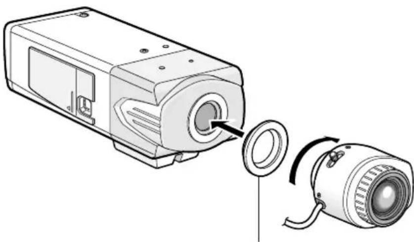
C-mount adaptor (accessory)
* Required for use of C-mount lens
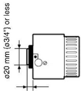
4.5 mm 5 / 32" or less
Optional dedicated lens
| Lens type Model No. | ||
| 1/2-inch type {1/2"} variable focal lens | 2 x varifocal | WV-LZ80/2 |
| 1/2-inch type {1/2"} zoom lenses | 6 x Motorized | WV-LZ81/6A |
| 10 x Motorized | WV-LZ81/10 | |
Note:
- It is recommended to use a lens whose F number is F1.2 or greater.
When using a lens whose F number is smaller than F1.2, sharpness of image may be diminished.
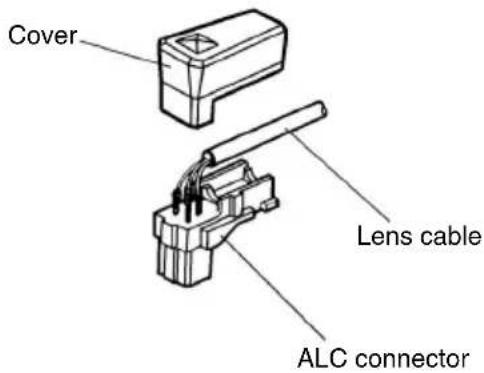
2 Connect the ALC connector (accessory) of the lens to the ALC lens connector of the camera.
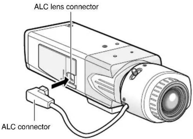
If an auto iris lens with a different shaped connector is used, replace the connector with the ALC connector (accessory).
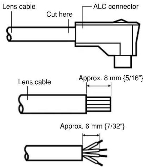
③ Solder the core wires to the pins of the ALC connector securely.
① Cut off the lens cable from the connector.
② Strip the end 8 mm {5/16"} of the lens cable outside cover, and then, remove each cover of the core wires by 6 mm {7/32"}.
Pin 1: Red (Power)
Pin 2: Not used
Pin 3: White (Video)
Pin 4: Black (Shield)
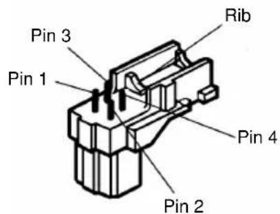
Put the cover on the ALC connector so that the lens cable is secured to the rib.
3 Fix an optional camera mounting base onto the desired place and mount the camera on it.
Use appropriate screws for the ceiling/wall material to secure an optional camera mounting base. Method of installation may be different depending on the material of the place where the camera mounting base is to be installed.
- When installing on steel: Fix with bolts and nuts (M6 or M8)
-
When installing on concrete: Fix with anchor bolts (M6 or M8)
-
The following are the requirements of the camera mounting base installation:
| Installing place | Appropriate cam- era mounting base | Recommended screw | Number of screw | Pull-out capacity of a single screw |
| On ceiling | WV-7010A | M6 or M8 | 3 pcs. | 196 N (20 kgf) |
| On wall | WV-831 M8 4 pcs. | 921 N (94 kgf) | ||
Important:
-
If the total weight of the camera and lens exceeds 1kg {2.2 lbs}, use a housing to take measures against camera drop.
-
When the tripod socket is mounted on the top of the camera, be sure to use the screws that were removed from the tripod socket. Use of longer or shorter screws may cause drop or damage. (Recommended tightening torque: 0.39 N·m {0.29 lbf·ft})
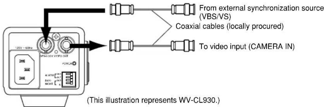
4 Establish the connection of a coaxial cable (locally procured).
Important:
- Be sure to turn off the power of each device before connection.
- Be sure to secure the coaxial cable connectors
Connect a coaxial cable (locally procured) to the video output connector. If the synchronizing signal input is provided from an external device, connect another coaxial cable to the external synchronization input connector.
Use a cable tie (locally procured) to attach the coaxial cable to the camera mounting base.
Important:
- The cable tie shall be made of metallic or durable material to be strong enough because the tie plays the role of camera drop prevention measures in case.
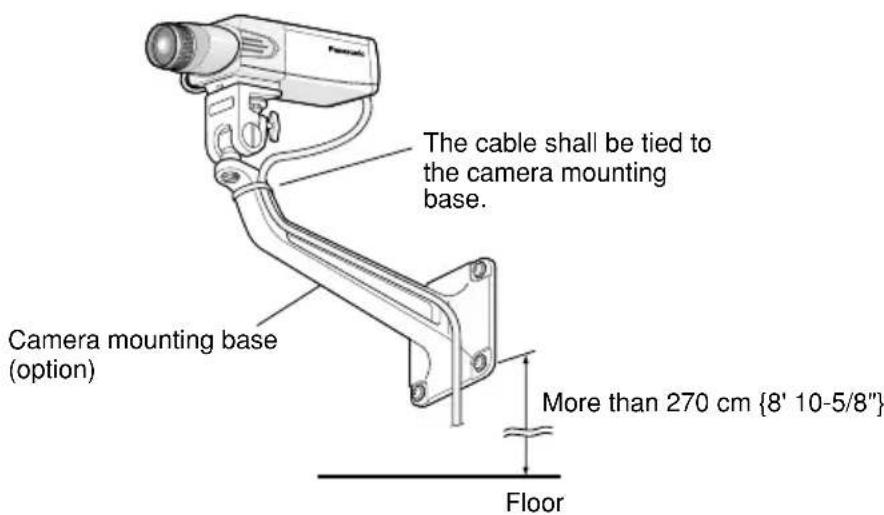
Important:
- When installing the camera mounting base on wall, installation height of the camera mounting base shall be as indicated in the illustration.
6 Connect the power cord and turn on the power.
WV-CL930
Connect between the power connector on the rear side of the camera and a plug socket with the supplied power cord.
WV-CL934
Select either 24 V AC or 12 V DC for power supply and connect the power supply to the AC/DC power terminal.
Caution:
To prevent fire or electric shock hazard, use a UL listed cable (VW-1, style 1007) for the 24 V AC or 12 V DC Input Terminal.
7 Adjust the camera angle by loosening the screw of the camera mounting base while viewing the video monitor.
Be sure to loosen the screw of the camera mounting base when the camera angle is adjusted. If the camera angle is changed when the screw is tight, excessive force is applied to the camera mounting base and camera, and accordingly they may be damaged. Be sure to tighten the screw securely after camera angle adjustment.
8 Adjust the focus.
When an auto iris lens is used, the originally adjusted focus may be slightly off depending on the iris state resulting from the focal depth of the lens. In such a case, open the iris by darkening the subject as much as possible and adjust the focus, and the focus-off state can be prevented.
Use of "ABF" of "BACK-FOCUS SETUP" in the setup menu (page 46) allows users to adjust the focus optimally in the range of the capability to automatically follow the variation in illuminance. (Note: The adjusted focal point is not necessarily the same as the optimal focal point at the specified illuminance.)
- The out-of-focus level in the near-infrared light region may be higher than that in the visible light region.
Setting "C/L B/W" of "BACK-FOCUS SETUP" to "AUTO" or "PRESET" in the setup menu allows users to adjust the focus in both the near-infrared light and visible light regions. (The variation in illuminance is not followed after focus adjustment.)
How to use varifocal lens/zoom lens
- Reset the back focus position to the CS mount default position before the back focus adjustment. (Press the right and left buttons among the operation buttons simultaneously, or move the cursor to "MANUAL-ADJ" of "BACK-FOCUS SETUP" in the setup menu and press the right and left buttons simultaneously after pressing the setting button.)
- Be aware that the adjustment method varies with varifocal lens or zoom lens models. For further information, refer to the operating instructions for the lens to be used.
Notes:
-
The adjustment procedure for general varifocal lenses is described as follows: For further information, refer to the operating instructions for the lens to be used.
-
Display a subject that exists as far as possible (10 m or more recommended) to adjust the back focus.
- For 8-, or 10-fold magnification lenses, adjust the back focus after setting the zoom to the WIDE end and setting the focus to the FAR end.
For 2-, or 3-fold magnification lenses, adjust the back focus after setting the zoom to the TELE end and setting the focus to the FAR end.
-
Adjust the view angle and focus coarsely by adjusting the zoom and focus of the lens to center a subject in the screen, and then perform the main adjustment of the back focus (15 pages 17 and 45).
-
When a non-Panasonic lens that has an extended range for lens focusing is used, adjust the back focus after setting the focus to a position at a short distance from the FAR end in Step 2 described above. If adjustment is performed in the extended range, appropriate adjustment cannot be obtained.
How to use fixed focus lens
- For a fixed focus lens with focus adjustment, adjust the back focus after setting the focus of the lens to the FAR end.
9 Adjusts the back focus.
Use the operation buttons ( page 9) for this operation.
The back focus is also adjustable in the setup menu. Refer to page 45 for how to operate and detailed explanation.
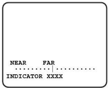
①Press the setting button after adjusting the view angle while viewing the video monitor.
The focus position indicator is displayed in the lower part of the screen, and the back focus is automatically adjusted.
③ To perform fine adjustment of the back focus after automatic back focus adjustment, use the right or left button.
Notes:
- No operation for more than 10 seconds automatically clears the focus position indicator.
- Pressing the right and left buttons simultaneously resets the back focus position to the CS mount default position.
Setting of external synchronization switch
When an external synchronizing signal input is provided to the external synchronization input connector on the rear side of the camera for loop through, select "Hi-Z". To terminate the connector, select "G/L 75 Ω". Select "G/L 75 Ω" for the normal situation, too.
External terminal
Important:
- Be sure to turn off the power of each device before connection.
Alarm output
Output specification: Open collector output (max. voltage: 16 V DC)
Off: 2 to 4VDC internally pulled up
On: Output voltage 1 V DC or less (max. drive current: 100 mA)
Color/black-and-white input
Input specification: No-voltage make contact input (3 to 5 V DC, internally pulled up)
Color: Open or 3 to 5 V DC
Black and white: Make contact with GND (required drive current: 0.2mA or more)
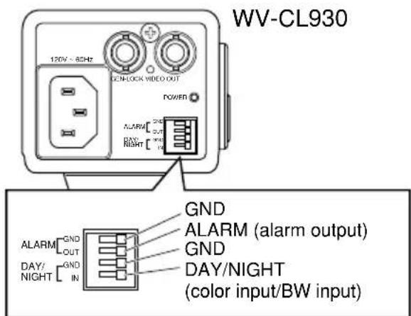
-
The external terminal is the same between WV-CL930 and WV-CL934.
-
When color input or black-and-white input is enabled, set the black-and-white switching, "BW MODE" to "EXT". (13 page 40)
- When an external device is connected, exercise care to avoid exceeding the rating.
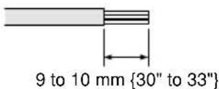
- Applicable wire: AWG22-AWG28, solid wire/stranded wire Strip the end 9 to 10mm (30" to 33") of the wire and insert it.
Setup Menus
Performing each setting item in the setup menu should be completed in advance to use this unit. Perform the settings for each item in accordance with the conditions of the camera shooting area.
The following is an example of setup procedure when LANGUAGE is set to ENGLISH.
Setup menu list
| Setup item | Description | Reference pages |
| CAMERA SETUP Performs the camera operation settings. | ||
| CAMERA ID Specifies the camera title. "CAMERA ID" creates the camera title that indicates the camera location and other information about the camera with alphanumeric, symbol, and displays on the screen. | 23 | |
| ALC/ELC Selects the method of controlling the quantity of light in accordance with the lens to be used. | 25 | |
| SHUTTER Specifies the electronic shutter speed. | 28 | |
| AGC Specifies gain adjustment. | 29 | |
| SENS UP Specifies electronic sensitivity enhancement. | 30 | |
| SYNC Specifies the synchronization type. | 31 | |
| WHITE BAL Specifies white balance adjustment. | 35 | |
| MOTION DET Specifies the motion detector mode. | 36 | |
| DNR Specifies the level of the digital noise reduction function. | 40 | |
| RESOLUTION Specifies the level of image resolution. | 40 | |
| BW MODE Performs each setting regarding the black-and-white mode such as switching between color and black-and-white images. | 40 | |
| PRIVACY ZONE Hides undesired portions in the camera shooting area. | 42 | |
| MIRROR Flips images horizontally. | 43 | |
| LENS-DRIVE Selects the drive control type in accordance with the lens to be used. | 43 | |
| STABILIZER | Decides whether or not to enable the image stabilizer. | 44 |
| BACK-FOCUS SETUP | Selects the back focus setting type and performs fine adjustment. | 45 |
| Setup item Description | Reference pages |
| SPECIAL SETUP | |
| CHROMAGAIN Adjusts the chroma level. | 47 |
| AP GAIN Adjusts the aperture level. | 47 |
| PEDESTAL Adjusts the pedestal level. | 47 |
| HUE Adjusts the chroma phase (hue) level. | 48 |
| PIX OFF Corrects image defect such as flaws. | 48 |
| COMMUNICATION Performsthe communication setting of the system with a receiver into which this unit is integrated. | 49 |
| CAMERA RESET Restores the settings in the setup menu to the default settings. | 49 |
| SER.NO. Displays the serial number of this unit. | 49 |
| LANGUAGE SETUP Selects a language to be used in the setup menu. | 50 |
■Basic operation
The description below explains how to operate the setup menu basically.
The operations in the setup menu are performed with the operation buttons (pages 9 - 10) after calling up the setup menu on the connected video monitor.
The operations in the setup menu can also be performed through the system controller (option).
Screenshot 1
Hold down the setting button for approx. 2 seconds to call up the top screen of the setup menu.
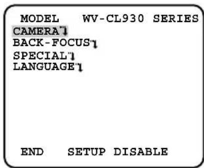
Step 1
Press the up button or the down button to move the cursor to "END".
Step 2
Press the right button to move the cursor to "SETUP", and press the setting button to change the setup mode from "DISABLE" to "ENABLE".
Screenshot 2
The setup mode changes to "ENABLE", and the setup menu becomes ready to be set.
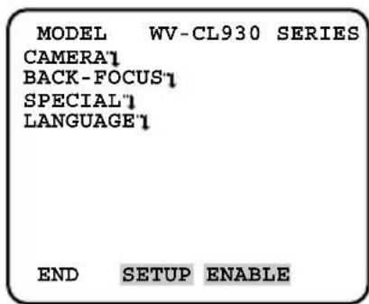
Step 3
Move the cursor to the item to be set, and press the setting button.
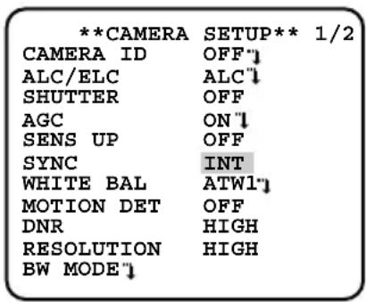
Screenshot 3
The selected setup screen in the setup menu appears on the screen.
| **CAMERA | SETUP** 1/2 |
| CAMERA ID | OFF'1 |
| ALC/ELC | ALC'1 |
| SHUTTER | OFF |
| AGC | ON'1 |
| SENS UP | OFF |
| SYNC | INT |
| WHITE BAL | ATWL'1 |
| MOTION DET | OFF |
| DNR | HIGH |
| RESOLUTION | HIGH |
| BW MODE'1 |
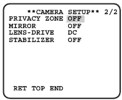
| **CAMERA | SETUP** 2/2 |
| PRIVACY ZONE | OFF |
| MIRROR | OFF |
| LENS-DRIVE | DC |
| STABILIZER | OFF |
| RET TOP END | |
Notes:
- If the top screen of the setup menu is called up while a camera image is displayed, the setup mode is always "DISABLE" to prevent operation errors. To perform settings in the setup menu, change the setup mode to "ENABLE".
- The cursor is a reversely highlighted part.
Step 4
Perform the settings for each item.
- Selection of setting item:
Press the up button or down button to move the cursor.
- Change of settings:
Press the right button or left button.
- Display of advanced setup screen:
Press the setting button when ^ is attached to the target setting item.
- Return to previous setup screen:
Move the cursor to "RET" and press the setting button.
- Return to top screen:
Move the cursor to "TOP" and press the setting button.
Step5
To return to the camera image screen, move the cursor to "END" and press the setting button.
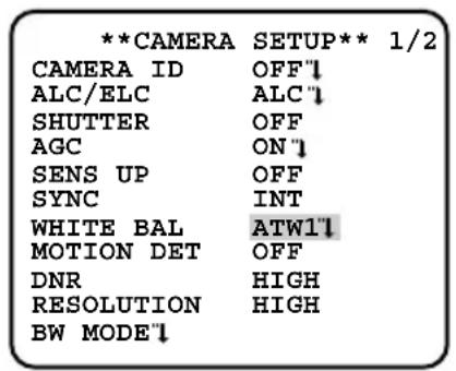
Camera Operation Setup [CAMERA SETUP]
The following describes the camera operation settings. The following settings are performed on the "CAMERA SETUP" screen through the top screen. Refer to pages 21 - 22 for how to call up the screen.
![PANASONIC WVCL930 - Camera Operation Setup [CAMERA SETUP] - 1](/content/2026/02/357382/images/e9da39a6bbb93f6012af7270aa03151bb3a08699594033698476a7453b405ef5.jpg)
![PANASONIC WVCL930 - Camera Operation Setup [CAMERA SETUP] - 2](/content/2026/02/357382/images/97f5bfcc9ce92950dcd3800b5530cf3da54b0d5d01cbaed5d12dbba5392d4b08.jpg)
1. Camera title setting [CAMERA ID]
This item specifies the camera title. The camera title that indicates the camera location and other information about the camera is created with alphanumeric characters and symbol, and displayed on the screen. The camera title is named with up to 16 characters. Follow the procedure below to specify the camera title.
"CAMERA SETUP" screen Title creation screen Display positioning screen
![PANASONIC WVCL930 - Camera title setting [CAMERA ID] - 1](/content/2026/02/357382/images/06705fc653064f2f519ab620b7feb80360af279d73d25698c92f2128afbb4083.jpg)
![PANASONIC WVCL930 - Camera title setting [CAMERA ID] - 2](/content/2026/02/357382/images/d5e245630ddadca4243ee1b315ea8de0490e8d69f762b7d4258156661f4c2a02.jpg)
![PANASONIC WVCL930 - Camera title setting [CAMERA ID] - 3](/content/2026/02/357382/images/459dc595ef075bd1550f432c4b96bf82a09b50a3e0c3c55871cc528228a573eb.jpg)
Editing area
Step 1
Set "CAMERA ID" to "ON" and press the setting button.
→The title creation screen appears.
Step 2
Move the cursor to the target item with use of the up, down, right, and left buttons, and press the setting button to enter the character.
→The entered characters are displayed in the editing area.
- To revise a character, move the cursor to the arrow () in the editing area, move the cursor () to the character to be revised with use of the right and left buttons, and enter a correct character.
- To enter a blank, move the cursor to "SPACE" and press the setting button.
- To delete all the entered characters, move the cursor to "RESET" and press the setting button.
Step 3
Move the cursor to "POSI" and press the setting button after title entry.
The display positioning screen appears.
Step 4
Use the up, down, right, and left buttons to decide the title position and press the setting button.
The camera title and title position are specified.
2. Method of controlling quantity of light [ALC/ELC]
The method of controlling the quantity of light is selected from the following in accordance with the lens to be used.
ALC (default): Adjusts the iris of the lens in accordance with the brightness of a subject. This selection is suitable for use of an auto iris lens (ALC lens).
ALC+: Controls the quantity of light with a combination of the electronic shutter and auto iris. This selection is suitable at shooting a bright subject such as an outdoor subject with auto iris lens. Be aware that flicker may occur when a subject is under fluorescent lighting.
ELC: Fixes the iris of the lens to a set value. This selection is suitable for use of a lens with fixed iris or manual iris.
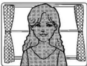
Backlight compensation
- If a subject has a bright light such as a spotlight in its background, the subject appears shadowy because the camera adjusts the iris in accordance with the bright area.
- To eliminate this phenomenon, masking bright areas allows users to perform backlight compensation to hide bright areas.
- Backlight compensation has two modes: One is the PRESET ON mode for automatic compensation after sensing the light conditions on the camera side, the other is PRESET OFF mode for specifying the sensing area manually.
[No backlight compensation performed] [Backlight compensation performed]

Nighttime
Daytime

Nighttime

Daytime
PRESET mode setting
"CAMERA SETUP" screen
| **CAMERA | SETUP** 1/2 |
| CAMERA ID | OFF |
| ALC/ELC | ALC |
| SHUTTER | OFF |
| AGC | ON |
| SENS UP | OFF |
| SYNC | INT |
| WHITE BAL | ATWL |
| MOTION DET | OFF |
| DNR | HIGH |
| RESOLUTION | HIGH |
| BW MODE |
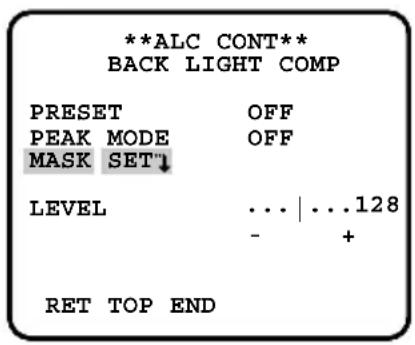
"ALC CONT" screen
| **ALC CONT** BACK LIGHT COMP | |
| PRESET | OFF |
| PEAK MODE | OFF |
| MASK SET | |
| LEVEL | ... | ...128 |
| - + | |
| RET TOP END | |
"ALC+CONT" screen
| **ALC+CONT** BACK LIGHT COMP | |
| PRESET | OFF |
| PEAK MODE | OFF |
| MASK SET | |
| LEVEL | ... | ...128 |
| - + | |
| RET TOP END | |
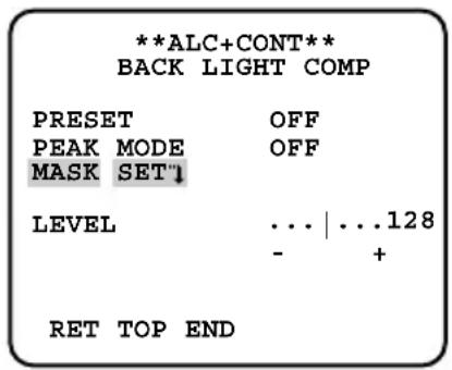
"ELC CONT" screen
| **ELC CONT** BACK LIGHT COMP | |
| PRESET | OFF |
| PEAK MODE | OFF |
| MASK SET" | |
| LEVEL | ... | ...128 |
| - + | |
| RET TOP END | |
Step 1
Move the cursor to "ALC", "ALC+", or "ELC" of "ALC/ELC" and press the setting button.
→The "ALC CONT", "ALC+CONT" or "ELC CONT" screen appears.
Step 2
Move the cursor to "PRESET" and use the right or left button to select "ON" or "OFF".
ON: Automatically performs backlight compensation.
OFF:Performs backlight compensation after specifying the compensation area.
When "OFF" is selected, "MASK SET" appears on the "ALC CONT", "ALC+CONT" or "ELC CONT" screen. (page 27)
Step 3
To change the video output level (image contrast), move the cursor to "LEVEL" and adjust the level with use of the right or left button.
Sensing area setting for backlight compensation
If backlight compensation does not function desirably in the PRESET ON mode, use the PRESET OFF mode, mask too bright areas manually and perform backlight compensation.
"ALC CONT" screen
"ALC+CONT" screen
"ELC CONT" screen

Mask setting screen

Step 1
Move the cursor to "PRESET" and use left or right button to select "OFF".
Step 2
Move the cursor to "MASK SET" and press the setting button to call up the mask screen. The mask setting screen shows 48-split areas and blinks the top and far left split area.
Step 3
Mask bright areas in the background.
① Move the blinking portion to the area to be masked with use of the right or left button.
② Press the setting button to mask the area. When the blinking portion is present on the masked area, the masked area is displayed with horizontal stripes and white alternately.
When the blinking portion is present on other areas, the masked area becomes white.
③Repeat the operation ②described above until masking is completed, and hold down the setting button for more than 2 seconds to resume the previous screen.
To cancel the masking, move the blinking portion to the masked area and press the setting button.
Step 4
To change the video output level (image contrast), move the cursor to "LEVEL" and adjust the level with use of the right or left button.
Flare compensation mode
If a lens flare is undesirable, move the cursor to "PEAK MODE" and use right or left button to select "ON".
ON: Performs flare compensation.
OFF (default): Does not perform flare compensation.
3. Electronic shutter setting [SHUTTER]
The variation in electronic shutter speed allows users to perform the following.
- Increased shutter speed prevents blurring fast-moving subjects.
The electronic shutter speed is selectable from the following:
OFF (1/60) (default), 1/100, 1/250, 1/500, 1/1000, 1/2000, 1/4000, and 1/10000
Notes:
- When "ALC/ELC" is set to "ELC" or "ALC+" (e8 page 25), the shutter setting cannot be performed. "OFF (1/60)" is automatically selected.
- If the controller, WV-CU254 or WV-CU204 is used, SW LED and the status of "SHUTTER" are not correctly displayed.
4. Gain control setting [AGC]
"CAMERA SETUP" screen
| **CAMERA | SETUP** 1/2 |
| CAMERA ID | OFF'1 |
| ALC/ELC | ALC'1 |
| SHUTTER | OFF |
| AGC | ON'1 |
| SENS UP | OFF |
| SYNC | INT |
| WHITE BAL | ATWL'1 |
| MOTION DET | OFF |
| DNR | HIGH |
| RESOLUTION | HIGH |
| BW MODE'1 |
"AGC MAX" screen
| ** AGC MAX ** |
| LEVEL . . .128 |
| - + |
| RET TOP END |
Step 1
Move the cursor to "AGC" and use right or left button to select "ON" or "OFF".
ON (default): Automatically increases the gain to make the screen brighter when the illuminance of the subject becomes darker. The maximum value is adjustable.
OFF: Does not increase the gain. (The normal image remains.)
Step 2
Move the cursor to "ON" and press the setting button to call up the "AGC MAX" screen.
Step 3
Move the cursor to "LEVEL". The cursor is reversely highlighted.
Move the cursor horizontally to adjust the gain with use of the right or left button.
Notes:
- Change in the level of "AGC MAX" causes change in the level of the input signal that enables electronic sensitivity enhancement when "SENS UP" is set to AUTO and also change in the level of the input signal that activates black-and-white mode.
- If noise is undesirable, adjust the level of "AGC MAX".
5. Electronic sensitivity enhancement setting [SENS UP]
Use of the electronic sensitivity enhancement function increases the quantity of light stored on the CCD, and accordingly the image becomes brighter. The magnification is unchanged for selection of FIX, and the magnification is changeable in accordance with the illuminance of a subject for selection of AUTO. The magnification of the electronic sensitivity is selectable from the following.
OFF (default)/X2 AUTO/X4 AUTO/X6 AUTO/X10 AUTO/X16 AUTO/X32 AUTO/X2 FIX/ X4 FIX/X6 FIX/X10 FIX/X16 FIX/X32 FIX/X64 FIX/X128 FIX
Notes:
- When the magnification of "SENS UP" is increased, the screen becomes coarser, more whitish, or more flawed. However, this phenomenon is normal.
- The status display of the system device does not show "X64 FIX" and "X128 FIX" of "SENS UP". In such cases, "X32 FIX" is shown.
- If the controller, WV-CU254 or WV-CU204 is used, SW LED and the status of "SENS UP" are not correctly displayed.
6. Synchronization setting [SYNC]
This unit supports the following 5 types of synchronization methods, and one of the following is selected.
The order of descriptions below indicates the order of priorities.
① Multiplexed vertical drive signal (VD2)
② Power supply synchronization (LL)
- Synchronization is performed on the basis of the power supply frequency.
③Composite color video signal or black burst signal (VBS)
④Monochrome composite video signal or composite synchronizing signal (VS)
⑤ Internal synchronization (INT) (default)
Input of a multiplexed vertical drive signal (VD2) automatically switches to the VD2 synchronization even if the camera is set to other than the VD2 synchronization method.
Adjustment of phase in power supply synchronization mode (LL)
The adjusting video signal of the camera and the critical external synchronizing input signal are connected to a 2-input oscilloscope and the phase is adjusted. Follow the procedure below to adjust the phase.
Note:
- Movement of the camera or presence of a spike noise in the power line may cause vertical phase change. In such a case, adjust the phase again.
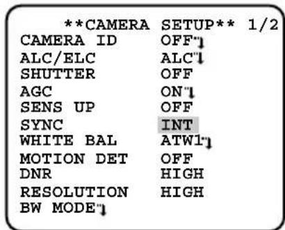
"CAMERA SETUP" screen
"SYNC" screen
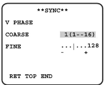
Step 1
Set "SYNC" to "LL" and press the setting button.
The "SYNC" screen appears.
Step 2
Connect the video output signal and external synchronizing input signal of the camera to a 2-input oscilloscope, and move the cursor to "COARSE".
Step 3
Adjust the oscilloscope to the vertical rate, and extend the vertical synchronizing part of the oscilloscope.
Move the cursor horizontally to adjust the vertical phase with use of the right or left button. The phase can be adjusted in 16 steps by 22.5 degrees.
Move the cursor to "FINE", and move the cursor horizontally with use of the right or left button to adjust both vertical phases.
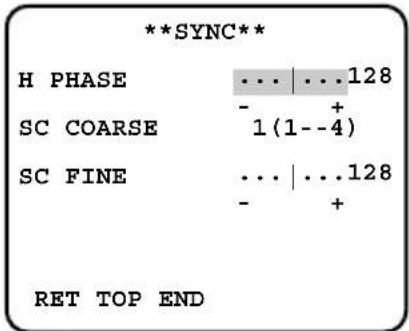
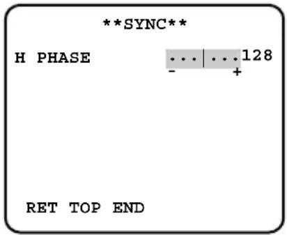
Adjustment of phase in VBS genlock mode (VBS)
The adjusting video signal of the camera and the critical external synchronizing input signal are connected to a 2-input oscilloscope and the phase is adjusted. Follow the procedure below to adjust the phase.
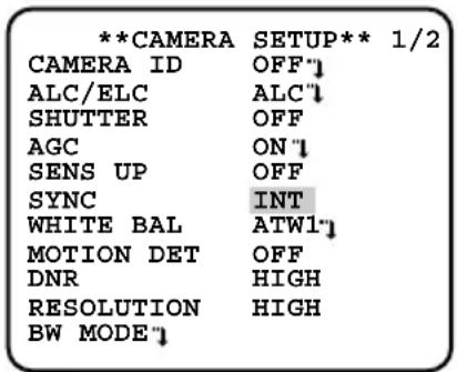
"CAMERA SETUP" screen
"SYNC" screen
Step 1
Provide a VBS signal to the external synchronizing input connector on the rear side of the camera.
The "SYNC" setting automatically changes to "EXT (VBS)".
Step 2
Move the cursor to "EXT (VBS)" and press the setting button.
→The "SYNC" screen appears.
Step 3
Connect the video output signal and external synchronizing input signal of the camera to a 2-input oscilloscope, and move the cursor to "H PHASE".
Step 4
Adjust the oscilloscope to the horizontal rate, and extend the horizontal synchronizing part of the oscilloscope.
Move the cursor horizontally to adjust the horizontal phase with use of the right or left button.
Adjustable range: 0 to -2.0 s
Step 5
Move the cursor to "SC COARSE" (subcarrier coarse adjustment), and use the following 4 steps to match the real color of the subject with the color of the effect output signal (program output video signal) of the special effect device (SEG) with use of right or left button.
$$ 1 (1 - - 4): 0 ^ {\circ} / 2 (1 - - 4): 9 0 ^ {\circ} / 3 (1 - - 4): 1 8 0 ^ {\circ} / $$
$$ 4 (1 - 4): 2 7 0 ^ {\circ} $$
Step 6
Move the cursor to "SC FINE" (subcarrier fine adjustment), and move the cursor horizontally with use of the right or left button to match the real color of the subject with the color of the program output video signal.
Notes:
- When the cursor moves to the right end "+" position, the cursor moves to the left end "-" position. At the time, the setting value of "SC COARSE" is incremented by 1, and adjustment is continuously performed.
- Holding down the right or left button for more than 1 second increases the cursor moving speed.
To achieve high precision adjustment, provide the video signal of the camera and program output signal to a vector chromaticity indicator to compare the macro phases of both signals.
Adjustment of phase in VS genlock mode (VS)
The adjusting video signal of the camera and the critical external synchronizing input signal are connected to a 2-input oscilloscope and the phase is adjusted. Follow the procedure below to adjust the phase.
"CAMERA SETUP" screen
"SYNC" screen
Step 1
Provide a VS signal to the external synchronizing input connector on the rear side of the camera.
The "SYNC" setting automatically changes to "EXT (VS)".
Step 2
Move the cursor to "EXT (VS)" and press the setting button.
The "SYNC" screen appears.
Step 3
Connect the video output signal and external synchronizing input signal of the camera to a 2-input oscilloscope, and move the cursor to "H PHASE".
Step 4
Adjust the oscilloscope to the horizontal rate, and extend the horizontal synchronizing part of the oscilloscope.
Move the cursor horizontally to adjust the horizontal phase with use of the right or left button.
Adjustable range: 0 to -2.0 s
7. White balance setting [WHITE BAL]
The white balance adjustment is selectable from the following.
ATW1 (default): Activates the automatic color temperature tracking mode. The camera continuously measures the color temperature of the light source and automatically adjusts the white balance. Manual fine adjustment is also enabled after automatic white balance setting. (page 36)
The adjustment of the color temperature ranges from approx. 2700K to 6000K . If the situation meets one of the following or other, color may not be accurately reproduced.
The subject is mostly highly-colored.
- The photographic atmosphere is under the bright blue sky or at nightfall.
- The illumination of the light illuminating the subject is low.
ATW2: Activates the sodium lamp automatic color temperature tracking mode. The camera automatically achieves an optimal white balance under the sodium lamp.
The adjustment of the color temperature ranges from approx. 2000K to 6 000 K.
AWC: Activates the automatic white balance control mode. This adjustment is suitable for a location where a light source is stable. The adjustment of the color temperature ranges from approx. 2000K to 10000K . When "AWC" is selected, the operation to adjust the white balance is required.
When "AWC" is selected, follow the steps below to adjust the white balance.
"CAMERA SETUP" screen
| **CAMERA | SETUP** 1/2 |
| CAMERA ID | OFF'1 |
| ALC/ELC | ALC'1 |
| SHUTTER | OFF |
| AGC | ON'1 |
| SENS UP | OFF |
| SYNC | INT |
| WHITE BAL | AWC'1 |
| MOTION DET | OFF |
| DNR | HIGH |
| RESOLUTION | HIGH |
| BW MODE1 |
Step 1
Set "WHITE BAL" to "AWC" and press the left button to change to "AWC PUSH SW".
Step 2
Press the setting button and adjust the white balance.
"PUSH SW" is reversely highlighted during adjustment. When the reversely highlighted display is restored, the white balance adjustment is completed.
Step 3
Press the right button to select "AWC".
Refer to the next page for fine adjustment of the white balance.
Note:
- The adjustment of the color temperature ranges from approx. 2000K to 10000K . If the correct range is out of this adjustment range or lighting directed to a subject is too dark, the white balance may not completely adjusted. In such a case, "PUSH SW" stays reversely highlighted.
Manual fine adjustment of white balance
The white balance is manually fine adjusted after white balance automatically adjustment in the automatic color temperature tracking mode (ATW) or automatic white balance control mode (AWC).
Follow the procedure below for white balance fine adjustment.
"CAMERA SETUP" screen
Fine adjustment screen
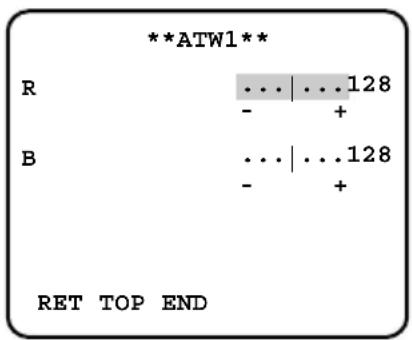
Step 1
Set "WHITE BAL" to "ATW1", "ATW2" or "AWC" and press the setting button.
The fine adjustment screen appears.
Step 2
Move the cursor to "R" and "B" and use the right or left button to fine adjust the level for each. "R" represents red and "B" represents blue. When the level indicator moves in the "+" direction, the color becomes deeper, and when the level indicator moves in the "-" direction, the color becomes lighter.
8. Motion detector function setting [MOTION DET]
The motion detector function is set. Either MODE1 or MODE2 is selected. When MODE1 is selected, the detailed settings such as settings of the detection sensitivity and detection area are required. The detection area can be specified and checked in the demonstration mode.
MODE1: Provides an alarm signal when a motion is detected.
MODE2: Provides an alarm signal when the camera is covered or the camera direction is changed.
OFF (default): Enables the motion detector function.
Description about motion detector function (MODE1)
This function split a screen into 48 blocks, detects brightness change in each block, and provides an alarm signal when a change (motion) is observed in the image of the shooting area.
This function allows users to record the camera image on a recording device when an alarm sounds.
Detection condition
Subject size: A moving subject needs to be equal to or larger than 1/48 of the screen at "STABILIZER OFF".
Subject contrast: The contrast ratio between the background and moving subject needs to be equal to or larger than 5% (at maximum sensitivity).
Subject moving speed: The passing time for a subject to move from the end to the other end of the screen needs to be equal to or larger than 0.8 seconds (at 5% of contrast ratio). A subject moving faster than the description above is undetectable.
Note:
- The larger the contrast ratio (difference between brightness and darkness) becomes, the less the limitation on the size and moving speed of a subject becomes.
Demonstration mode
The brightness change in each of 48-split blocks is detected, and the mask is covered on the block where the change in the average brightness exceeds the specified detection sensitivity level.
The adjustment of the detection sensitivity level and the setting of the detection areas are repeated to obtain an optimal state on the basis of the results in the demonstration mode.
Description about motion detector function (MODE2)
This function provides an alarm signal when a change in the state of a subject occurs by covering the camera with a cloth, a cap, or others, or by changing the camera direction largely.
Important:
- A change in the state of a subject may not be detected in the following cases:
- When only a part of the lens is hidden, or the cover is transparent,
- When the subjects are similar between before and after changing the camera direction.
- False detection may occur in the following cases:
- When a change in brightness is significant such as turning on and off a light,
- When the traffic volume including people and cars is high.
Advanced settings about motion detector function (MODE1)
The description below specifies the sensitivity level and detection area of the motion detector (MODE1).
To perform mask setting, set the image stabilizer, i.e. "STABILIZER" to "OFF". ( page 44)
"CAMERA SETUP" screen
| **CAMERA | SETUP** 1/2 |
| CAMERA ID | OFF"1 |
| ALC/ELC | ALC"1 |
| SHUTTER | OFF |
| AGC | ON"1 |
| SENS UP | OFF |
| SYNC | INT |
| WHITE BAL | ATW1"1 |
| MOTION DET | OFF |
| DNR | HIGH |
| RESOLUTION | HIGH |
| BW MODE"1 |
"MODE 1" screen
| **MODE1** | |
| LEVEL | ...|...128 |
| - + | |
| DWELL TIME | 2S |
| DISPLAY MODE" | |
| ALARM | OFF |
| MASK SET" | |
| RET TOP END | |
Mask setting screen
Step 1
Set "MOTION DET" to "MODE1" and press the setting button.
→The "MODE1" screen appears.
Step 2
Move the cursor to "MASK SET" and press the setting button.
The mask setting screen appears.
Step 3
Perform mask setting. The operation procedure is the same as the masking operation in the process of Sensing area setting for backlight compensation. (page 27)
Step 4
Hold down the setting button for approx. more than 2 seconds after completion of masking.
The "MODE1" screen appears again.
Step 5
Move the cursor to "ALARM", and decide whether or not to provide an alarm signal in the demonstration mode with use of "ON" or "OFF".
ON: Provides an alarm signal output in the demonstration mode, and allows users to check the operation on the monitor when a motion is detection.
OFF (default): Provides no alarm signal output in the demonstration mode.
Step 6
Move the cursor to "DISPLAY MODE" and press the setting button.
→The demonstration mode is implemented, and the blocks on which significant brightness change was detected blink.
Step 7
Press the setting button.
→The demonstration mode is terminated, and "MODE1" screen appears again.
Step 8
Move the cursor to "LEVEL" and use the right or left button to adjust the detection sensitivity level. When the level indicator moves in the "+" direction, the level becomes higher. When the level indicator moves in the "-" direction, the level becomes lower.
Repeat from Step 6 to Step 8 to obtain an optimal level.
Step 9
Move the cursor to "DWELL TIME" and select an alarm detection skipping time from the following:
2S (default)/5S/10S/30S (S: Second)
Selection of an alarm detection skipping time disables the detection of an alarm until a lapse of a specified time after detecting an alarm once.
Important:
- When a curtain swaying in the wind is detected, use the masking function to exclude the curtain from the detection area.
- When the noise level is high under low illuminance lighting resulting in malfunction, decrease the sensitivity (LEVEL). When the illuminance of a subject changes abruptly, e.g. caused by car headlights or turning on and off a light, false detection may occur.
- Approximately 0.2-second delay exists between detection of a change (motion) in image with this unit and alarm signal output. When the setup menu is displayed, an alarm output is not provided. (The case that "ALARM" is set to ON in the demonstration mode is excluded.)
- Selection of "ON" for the motion detector function causes a malfunction with a device that uses a VCR time code because an alarm data output is provided during blanking. In such a case, set the motion detector function to "OFF".
- The motion detector function is not exclusively used for prevention of theft, fire, etc. We are not responsible for any accidents or damages occurring in case.
9. Digital noise reduction function setting [DNR]
The digital noise reduction function reduces noise automatically under the condition of low illuminance. The effect level of the noise reduction function is selectable from the following:
LOW: Low level of noise reduction (small residual image)
MID: Medium level of noise reduction (medium residual image)
HIGH (default): High level of noise reduction (large residual image)
10. Image resolution setting [RESOLUTION]
A resolution of camera images is selectable from the following:
NORMAL: Horizontal resolution of 480 TV lines or more
HIGH (default): Horizontal resolution of 540 TV lines typ.
Note:
- When the electronic sensitivity enhancement function, "SENS UP", is activated under the condition that "HIGH" is selected, noise may increase.
11. Settings in black-and-white mode [BW MODE]
The settings regarding the black-and-white mode are performed.
Follow the procedure below for settings regarding the black-and-white mode.
"CAMERA SETUP" screen "BW MODE" screen "BW MODE" screen
![PANASONIC WVCL930 - Settings in black-and-white mode [BW MODE] - 1](/content/2026/02/357382/images/19d65298491bcb4109f8be222203b148876914748d2d2d12055cdf2f44809ff1.jpg)
![PANASONIC WVCL930 - Settings in black-and-white mode [BW MODE] - 2](/content/2026/02/357382/images/1ad16424102cfb56b81dca9dc621638e132fbdc23374ada35ba1fd7dce33f19d.jpg)
![PANASONIC WVCL930 - Settings in black-and-white mode [BW MODE] - 3](/content/2026/02/357382/images/c33474b24e7d549ea9d0c6b90e34a219091f71c6595d7e103921b93a8ab6889c.jpg)
Step 1
Move the cursor to "BW MODE" and press the setting button.
The "BW MODE" screen appears.
Step 2
Move the cursor to "BW" and select the black-and-white control from the following:
AUTO1: Automatically toggles between color and black-and-white images in accordance with the screen brightness (illuminance). The black-and-white mode is selected for dark images, and the color mode is selected for bright images.
AUTO2: Uses a near-infrared light source at nighttime.
EXT: Is selected to control switching between color and black-and-white images after connecting an external device to the external terminal (DAY/NIGHT). ( page 18)
ON: Displays black-and-white images.
OFF (default): Displays color images.
Note:
- If a subject is always moving or the screen is occupied with a uniform color, brightness determination may be not performed successfully because the brightness is merely determined by information from the CCD image sensor. When "AUTO2" is selected, the wave length of the light source shall be 800 nm or longer.
Step 3
Move the cursor to "LEVEL" and select a brightness level at which switching between color and black-and-white images is performed from the following:
LOW: Switches from color to black-and-white images when the ambient brightness (illuminance) of the camera is approx. 0.1 lx or less. (when the AGC MAX level is set to the top end.)
HIGH (default): Switches from color to black-and-white images when the ambient brightness (illuminance) of the camera is approx. 0.2 lx or less. (when the AGC MAX level is set to the top end.)
Step 4
Move the cursor to "DURATION TIME" and select a time for switching between color and black-and-white images from the following: (Default: 30 seconds)
10 sec.-30 sec.-60 sec.-300 sec.
(S) (L)
Step 5
Move the cursor to "BURST (BW)", and decide whether or not to provide a burst signal output in the black-and-white mode with use of "ON" or "OFF".
ON (default): Provides a burst signal output.
OFF: Does not provide any burst signal output.
Notes:
- The auto back focus function also allows users to correct out of focus when changing between color and black-and-white images. (page 45)
- Images may not be displayed appropriately without burst signals when camera images are displayed in the black-and-white mode depending on a monitor or VCR model to be used. In such a case, set the burst signal output to "ON".
12. Privacy zone setting [PRIVACY ZONE]
When undesired portions in the camera shooting area (on the screen) exist, those portions (privacy zone) are hidden.
ON (1): Grays the zone.
ON (2): Mosaics the zone.
OFF (default): Displays the zone normally.
Up to 8 portions can be specified for the privacy zone. Follow the procedure below for privacy zone setting.
Note:
- The privacy zone function is disabled at initializing the unit, i.e. right after turning on the power.
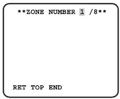
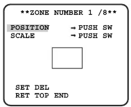
"CAMERA SETUP" screen Zone number selection screen Zone setting screen
Step 1
Move the cursor to "PRIVACY ZONE", select "ON (1)" or "ON (2)", and press the setting button.
→The zone number selection screen appears.
Step 2
Use the right or left button to select the target zone number after ascertaining that the cursor is present on "1" of "1/8" located at the right side of "ZONE NUMBER". When a zone number is marked with ^** at its right side, the zone with the number is already set to the privacy zone.
Step 3
Press the setting button after zone number selection.
The zone setting screen appears.
Notes:
- When a zone number that is already set to the privacy zone in Step 3 is selected, the image of the zone is displayed in the zone frame on the zone setting screen. Performing Step 4 and Step 5 clears the setting zone and implements new zone setting.
- To cancel the zone setting, move the cursor to "DEL" and press the setting button. The zone setting is canceled.
Step 4
Move the cursor to "POSITION" and press the setting button.
Step 5
Use the up, down, right, and left buttons to decide the zone position and press the setting button.
The zone position is determined.
Step 6
Move the cursor to "SCALE" and use the up, down, right and left buttons to adjust the zone frame size. The up and down buttons decide the vertical size, and the right and left buttons decide the horizontal size. Press the setting button after the zone frame size setting.
Step 7
Move the cursor to "SET" and press the setting button.
→The zone is determined and the zone number selection screen appears again.
13. Image horizontal flip [MIRROR]
"ON" or "OFF" is selected to decide whether or not to flip images horizontally. Image horizontal flip is selected in accordance with the camera location (usage environment).
ON: Flips camera images horizontally.
OFF (default): Does not flip camera images horizontally.
14. Lens type setting [LENS-DRIVE]
The drive control type is selected in accordance with the lens to be used.
DC (default): Is selected to use an auto iris lens with DC control type.
VIDEO: Is selected to use an auto iris lens with video signal type.
15. Image stabilizer setting [STABILIZER]
"ON" or "OFF" is selected to decide whether or not to enable the image stabilizer.
This function is effective for the case that the camera is installed on a power pole or other poles.
ON: Enables the image stabilizer.
OFF (default): Disables the image stabilizer.
Important:
- When "ON" is selected for the image stabilizer, the view angle becomes narrower and the resolution becomes lower. When "ON" is selected for the image stabilizer, check the view angle and resolution at camera installation.
-
The image stabilizer function may not work for the following subjects or conditions:
-
Dark subject
Less contrasty subject (e.g. white wall) - Short cycled image shaking such as mechanical vibration
Large amplitude image shaking
Back focus setting [BACK-FOCUS SETUP]
The back focus setting type is selected and fine adjustment is performed. The following setting is performed on the "BACK-FOCUS SETUP" screen through the top screen. Refer to pages 21 - 22 for how to call up the screen. The lens adjustment (u3 pages 15 - 17) shall be performed before the back focus adjustment.
The back focus adjustment is performed by changing the distance between the lens and focal point.
Important:
- The auto back focus function is used for back focus adjustment at installation and for focus correction at switching between the color and black-and-white modes after installation. This function is not a function that is supposed to be operated continuously such as the auto focus function.
- When focus missing occurs due to secular change in the lens and installation environment or peripheral temperature change, the back focus adjustment is required again.
Note:
- The back focus adjustment can be also performed through the operation buttons. (F page 9)
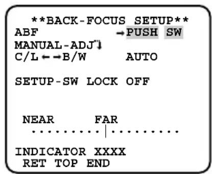
"BACK-FOCUS SETUP" screen
Note:
- "ABF" is available when "SENS UP" is set to "OFF", "X2 AUTO", or "X2 FIX".
Step 1
Move the cursor to "PUSH SW" of "ABF" and press the setting button.
→The auto back focus function provides back focus adjustment to automatically focus on a subject located in the center of the screen.
Step 2
To fine adjust the back focus, move the cursor to "MANUAL-ADJ", press the setting button, and use the right or left button to adjust the back focus manually.
Notes:
- Pressing the right and left buttons simultaneously resets the back focus position to the CS mount default position.
- The value of "INDICATOR" is a guide to adjust the back focus. The larger the value is, the sharper the image becomes.
Step 3
Move the cursor to "C/L B/W" and select the back focus adjustment type from the following:
AUTO (default): Adjusts the back focus function automatically and corrects out of focus when switching between color and black-and-white images.
PRESET: Performs the preset movement to each specified back focus position when switching between color and black-and-white images. The preset position is the back focus position specified last time, which was automatically memorized for each of color images and black-and-white images.
FIX: Fixes the position after adjusting the back focus either automatically (ABF) or manually.
Note:
- "AUTO" of "C/L B/W" is available when "SENS UP" is set to "OFF", "X2 AUTO", or "X2 FIX".
Step 4
Moving the cursor to "SETUP-SW LOCK" and selecting "ON" allow users to disable the back focus adjustment with the operation buttons. (page 17)
Important:
- The following are recommendation for back focus setting in accordance with subjects.
| For such case (subject conditions) | Select this (recommendation) | |
| Back focus adjustment | "C/L←→B/W" switching | |
| ·Normal subject "ABF" "AUTO" | ||
| ·Frequently moving subj. ·Subj. with remarkable illuminance change ·Subj. with low illuminance ·Too bright or reflective subj. ·Subj. through a window ·Place where the lens easily becomes dirty ·Subj. with less contrast such as white wall ·Subj. with remarkable depth ·Subj. with heavy flicker ·Subj. with horizontally parallel lines such as a shutter | Fine adjustment with "MANU-AL-ADJ" after "ABF" or "MANU-AL-ADJ" | "PRESET" or "FIX" |
| ·We shall not responsible for any inconvenience, loss, or damage caused by the settings or results of the back focus function. | ||
Special Menu Setup [SPECIAL SETUP]
The special menu setup is performed including the setting of the camera image quality and the communication configuration when a receiver is used. The following settings are performed on the "SPECIAL SETUP" screen through the top screen. Refer to pages 16 - 17 for how to call up the screen.
![PANASONIC WVCL930 - Special Menu Setup [SPECIAL SETUP] - 1](/content/2026/02/357382/images/b8b251e9342173ae1445d686669dcb3cfdab660ebffa795e0b075b947ea06093.jpg)
Chroma level adjustment [CHROMAGAIN]
Use the right or left button to adjust the color density of the camera image. When the level indicator moves in the "+" direction, the color becomes deeper. When the level indicator moves in the "-" direction, the color becomes lighter. Be sure to view a vector chromaticity indicator or a monitor when the adjustment is performed.
Aperture level adjustment [AP GAIN]
Use the right or left button to adjust the image quality. When the level indicator moves in the "+" direction, the image becomes sharper. When the level indicator moves in the "-" direction, the image becomes softer. Be sure to view a monitor when the adjustment is performed.
Note:
- Moire (interference fringes) may be observed when shooting a subject with fine pattern such as a carpet or a curtain. In such a case, move the indicator in the "-" direction to reduce moiré.
Pedestal level adjustment [PEDESTAL]
Use the right or left button to adjust the pedestal level of the camera. When the level indicator moves in the "+" direction, the image becomes brighter. When the level indicator moves in the "-" direction, the image becomes darker. Be sure to view a waveform monitor or a monitor when the adjustment is performed.
Chroma phase level (hue) adjustment [HUE]
Use the right or left button to adjust the hue of the camera image. Be sure to view a vector chromaticity indicator or a color video monitor when the adjustment is performed.
Note:
- Holding down the right and left buttons for more than 2 seconds simultaneously restores the settings of "CHROMAGAIN", "AP GAIN", "PEDESTAL", and "HUE" to the default settings.
Pixel compensation [PIX OFF]
Flaws in the displayed camera image are corrected, which is called pixel compensation. Up to 16 points can be corrected. Follow the procedure below to perform pixel compensation.
"SPCEIAL SETUP" screen "PIX OFF" screen
![PANASONIC WVCL930 - Pixel compensation [PIX OFF] - 1](/content/2026/02/357382/images/813206462f1382ee11ae67fc0ea1b7f159d26c8b182686bf456c92eae8d808f9.jpg)
![PANASONIC WVCL930 - Pixel compensation [PIX OFF] - 2](/content/2026/02/357382/images/91273af9333c21811ad251d6de31b4d499f80debfc99d80705f04740c3c52319.jpg)
Pixel compensation positioning screen
![PANASONIC WVCL930 - Pixel compensation [PIX OFF] - 3](/content/2026/02/357382/images/3716342f3cd38a3e10890bebe57525c5c08681d02315882bc46791c17f74e75b.jpg)
Step 1
Move the cursor to "PIX OFF" and press the setting button.
The "PIX OFF" screen appears.
Step 2
Select a number (1 to 16) with which a pixel compensation point is registered and press the setting button.
The pixel compensation positioning screen appears.
Step 3
Use the up, down, right, and left buttons to move the crosshair cursor to the center of the flaw to be corrected and press the setting button.
The flaw is corrected and the pixel compensation point is registered. The "PIX OFF" screen appears again. "★" is attached at the right side of the number when registration is completed. The coordinate is expressed in figures.
Notes:
- To clear the registered pixel compensation point, move the cursor to the number with which the target pixel compensation point is registered on the "PIX OFF" screen and press the setting button. The pixel compensation positioning screen appears, and then hold down the right and left buttons for more than 2 seconds simultaneously. The "PIX OFF" screen appears, the pixel compensation point is cleared, and * at the right side of the number disappears.
- When an auto iris lens with video signal type is used, the pixel compensation shall be performed after darkening the screen.
- The auto pixel compensation function starts up to automatically detect flaws by moving the cursor to "RET" on the "PIX OFF" screen and pressing the right and left buttons simultaneously. If there are points that seem to be flaws in the dark screen, up to 15 points are automatically detected and registered. In addition, once the auto pixel compensation function is activated, all of the registered pixel compensation points are cleared.
Communication configuration [COMMUNICATION]
The required communication configuration is performed to use this unit integrated into the system with a receiver.
COAX (RCV): Uses our receiver (e.g. WV-RC100 or WV-RC150).
COAX (default): Does not use any receiver.
Default restoring [CAMERA RESET]
The settings in the setup menu are restored to the default settings.
The default settings are restored by moving the cursor to "PUSH SW" of "CAMERA RESET" and holding down the right, left, and setting buttons for more than 2 seconds simultaneously.
Notes:
- The data of the registered pixel compensation points is not cleared.
- "ABF" settings cannot be initialized.
Serial number viewing [SER.NO.]
The serial number of this unit appears.
Language Selection [LANGUAGE SETUP]
A language for the setup menu is selected from the following: The language selection is performed on the "LANGUAGE SETUP" screen through the top screen.
JAPANESE/ENGLISH (Default)/FRANÇAIS/ESPÁNOL/DEUTSCH/ITALIANO/PYCCKIM
![PANASONIC WVCL930 - Language Selection [LANGUAGE SETUP] - 1](/content/2026/02/357382/images/634f2043957874acc33c252ace53ea93d664d8d75a9fa0d224d3ff8c2a96d628.jpg)
To change the language to be used, use the right or left button to select the target language, move the cursor to "SET", and press the setting button.
Notes:
- When the language is changed, the specified camera title is cleared.
- Only when Japanese is selected, katakana characters can be used for the camera title.
Shortcut Operation
Use of a system controller with the "camera function" button allows users to perform the shortcut settings with use of the numeric keypad and camera function button. The available shortcut operations with this unit are shown as follows:
| System controller operation Setting contents |
| [8] + [4] + [Camera function] BLC PRESET ON |
| [8] + [5] + [Camera function] BLC PRESET OFF |
| [9] + [0] + [Camera function] Black-and-white control (BW) ON |
| [9] + [1] + [Camera function] Black-and-white control (BW) OFF |
| [9] + [2] + [Camera function] Black-and-white control (BW) AUTO 1 |
| [9] + [3] + [Camera function] Camera ID (CAMERA ID) ON |
| [9] + [4] + [Camera function] Camera ID (CAMERA ID) OFF |
| [1] + [6] + [9] + [Camera function] Iris of lens (IRIS) OPEN |
| [1] + [7] + [0] + [Camera function] Iris of lens (IRIS) CLOSE |
| [1] + [7] + [1] + [Camera function] Electronic shutter (SHUTTER) ON |
| [1] + [7] + [2] + [Camera function] Electronic shutter (SHUTTER) OFF |
| [1] + [7] + [3] + [Camera function] Electronic shutter speed, 1 step faster |
| [1] + [7] + [4] + [Camera function] Electronic shutter speed, 1 step slower |
| [1] + [7] + [5] + [Camera function] Gain adjustment (AGC) ON |
| [1] + [7] + [6] + [Camera function] Gain adjustment (AGC) OFF |
| [1] + [7] + [7] + [Camera function] Electronic sensitivity up (SENS UP) FIX ON |
| [1] + [7] + [8] + [Camera function] Electronic sensitivity up (SENS UP) FIX OFF |
| [1] + [7] + [9] + [Camera function] Electronic sensitivity, 1 step up (FIX) |
| [1] + [8] + [0] + [Camera function] Electronic sensitivity, 1 step down (FIX) |
| [1] + [8] + [1] + [Camera function] Electronic sensitivity up (SENS UP) AUTO ON |
| [1] + [8] + [2] + [Camera function] Electronic sensitivity up (SENS UP) AUTO OFF |
| [1] + [8] + [3] + [Camera function] Electronic sensitivity, 1 step up (AUTO) |
| [1] + [8] + [4] + [Camera function] Electronic sensitivity, 1 step down (AUTO) |
| [1] + [8] + [5] + [Camera function] Power supply synchronizing phase adjustment (FINE), 1 step up |
| [1] + [8] + [6] + [Camera function] Power supply synchronizing phase adjustment (FINE), 1 step down |
| [1] + [9] + [0] + [Camera function] BW AUTO 1 switching time, 10 sec. |
| [1] + [9] + [1] + [Camera function] BW AUTO 1 switching time, 30 sec. |
| [1] + [9] + [2] + [Camera function] BW AUTO 1 switching time, 60 sec. |
| [1] + [9] + [3] + [Camera function] BW AUTO 1 switching time, 300 sec. |
| [2] + [0] + [1] + [Camera function] Image stabilizer (STABILIZER) ON |
| [2] + [0] + [2] + [Camera function] Image stabilizer (STABILIZER) OFF |
Troubleshooting
Before asking for repairs, check the symptoms with the following table.
Contact your dealer if a problem cannot be solved even after checking and trying the solution in the table or a problem is not described below.
| Symptom | Cause/solution | Reference pages |
| No image displayed | • Are the power cord and coaxial cable connected appropriately?→ Check whether the connection is appropriately established. | 14 - 15 |
| • Is the monitor luminance appropriately adjusted, or is the contrast appropriately adjusted?→ Check whether the monitor settings are appropriate. | - | |
| • Is the lens cap detached?→ Check whether the cap is detached from the lens. | - | |
| Blurred image | • Is the lens of the camera soiled with dirt or dust?→ Check whether the lens of the camera is clean. | - |
| • Is the focus adjusted correctly?→ Check if the focus is adjusted correctly. | 15 - 17 | |
| Damaged power cord sheathing | The power cord, connector, or power plug is damaged. Use of the damaged cord, connector, or plug may cause electric shock or fire. Disconnect the power plug immediately and request repair to your dealer. | - |
| Heated portion of power line consisting of power cord, connector, and power plug during use | ||
| Warmed power cord or loosened connection by bending or stretching during use. |
Specifications
| Power source: WV-CL930: 120 V AC, 60 Hz 4.6 W WV-CL934: 24 V AC, 60 Hz 4.0 W or 12 V DC 350 mA | |
| Image sensor: 1/2-inch type {1/2"} interline transfer CCD | |
| Effective pixels: 768 (H) x 494 (V) | |
| Scanning area: 6.4 mm (H) x 4.8 mm (V) | |
| Scanning system: 2:1 interlace | |
| Scanning frequency: Horizontal: 15.734 kHz, Vertical: 59.94 Hz | |
| Synchronization: Internal (INT), line-lock (LL), external synchronization (VBS/VS), multiplexed vertical drive (VD2) | |
| Resolution: Horizontal: 570 TV lines (BW mode), 540 TV lines typ., 520 TV lines (color mode, resolution: HIG Vertical: 350 TV lines (at center) | |
| Minimum illumination: BW mode: 0.008 lx (F1.4) | |
| Color mode: 0.09 lx (F1.4) | |
| Signal-to-noise ratio: 50 dB (AGC Off) | |
| Video output: | VBS 1.0 V[P-P]/75 Ω, composite signal, BNC connecto |
| External sync input: | VBS/VS 1.0 V[P-P]/75 Ω, composite signal, BNC conne |
| Lens mount: CS-mount | |
| ALC drive: | DC drive/Video drive switchable |
| External terminal: | ALARM: Open collector output (16 V DC or less) DAY/NIGHT: 5 V DC pulled up |
| Functions: | |
| Camera title: | Up to 16 characters (alphanumeric characters, marks) |
| Light control: | ALC/ALC+/ELC |
| Electronic shutter speed: | OFF (1/60), 1/100, 1/250, 1/500, 1/1 000, 1/2 000, 1/4 000 1/10 000 |
| Gain control: | ON (adjustable)/OFF |
| Sensitivity up: | OFF/X2 AUTO/X4 AUTO/X6 AUTO/X10 AUTO/X16 AUTO AUTO/X2 FIX/X4 FIX/X6 FIX/X10 FIX/X16 FIX/X32 FIX/X16 X128 FIX |
| Synchronization: | INT (internal sync)/VD2/VS*/VBS* (auto swichng)/ LL* (power supply synchronization) |
| * Phase adjustable | |
| White balance: | ATW1/ATW2/AWC |
| Video motion detection: | MODE1/MODE2/OFF |
| Digital noise reduction: | LOW/MID/HIGH |
| Resolution: | NORMAL/HIGH |
| Black-and-white mode: | AUTO1/AUTO2/EXT/ON/OFF |
| Privacy zone: ON (1)/ON (2)/OFF | |
| Horizontal flip: | ON/OFF |
| Lens drive: | DC/VIDEO |
| Image stabilizer: ON/OFF | |
| Back focus: | ABF (AUTO/PRESET/FIX), MANUAL-ADJ |
| Special: | CHROMAGAIN, AP GAIN, PEDESTAL, HUE, PIX OFF |
Ambient operating
temperature: -10^ to +50^ {14°F to 122°F}
Ambient operating humidity: Less than 90%
Dimensions: WV-CL930: 70 (W) x 65 (H) x 151 (D) mm
$$ {2 - 3 / 4 ^ {\prime \prime} (W) \times 2 - 9 / 1 6 ^ {\prime \prime} (H) \times 5 - 1 5 / 1 6 ^ {\prime \prime} (D) } $$
(Connectors and terminals excluded)
(Connectors and terminals excluded)
Weight: WV-CL930: 570 g {1.26 lbs} (Power cord excluded)
WV-CL934: 560 g {1.24 lbs}
Finish: Black (Munsell 5.0 PB/2.9/0.3 or equivalent)
Gray (Munsell 4.4 G/4.0/0.1 or equivalent)
Weights ad dimensions indicated are approximate.
Specifications are subject to change without notice.
Standard Accessories
Operating Instructions (this book) 1 pc.
Warranty card 1 pc.
The following is for installation.
Power cord (WV-CL930 only) 1 pc.
ALC connector 1 pc.
C-mount adaptor 1 pc.
VERSION FRANÇAISE
(FRENCH VERSION)
CAUTION
RISK OF ELECTRIC SHOCK DO NOT OPEN

ATTENTION: AFIN DE PREVENIR LE RISQUE DE CHOCSELECTRIQUES, NE PAS RETIRER LES VIS.
TOUTE RÉPARATION DEVRAIT ÉTRE CONFIEE À UN PERSONNEL QUALIFIÉ.
Dimensions: WV-CL930: 70 mm (L) × 65 mm (H) × 151 mm (P)
2 - 3 / 4^ (L)× 2 - 9 / 16^ (H)× 5 - 15 / 16^ (P)
WV-CL934: 70 mm (L) x 65 mm (H) x 151 mm (P)
2 - 3 / 4^ (L)× 2 - 9 / 16^ (H)× 5 - 15 / 16^ (P)
Panasonic System Networks Company of America, Unit of Panasonic Corporation of North America
www.panasonic.com/business/
For customer support, call 1.800.528.6747
Three Panasonic Way, Secaucus, New Jersey 07094 U.S.A.
Panasonic Canada Inc.
5770 Ambler Drive, Mississauga, Ontario, L4W 2T3 Canada
(905)624-5010
www.panasonic.ca
© Panasonic System Networks Co., Ltd. 2010