GPVD151 - Surveillance Camera PANASONIC - Free user manual and instructions
Find the device manual for free GPVD151 PANASONIC in PDF.
User questions about GPVD151 PANASONIC
0 question about this device. Answer the ones you know or ask your own.
Ask a new question about this device
Download the instructions for your Surveillance Camera in PDF format for free! Find your manual GPVD151 - PANASONIC and take your electronic device back in hand. On this page are published all the documents necessary for the use of your device. GPVD151 by PANASONIC.
USER MANUAL GPVD151 PANASONIC
Operating Instructions
Installation Instructions provided
HD Communication Camera
Model No.
GP-VD151, GP-VD151A
HOMI
Before operating this product, please read the instructions carefully and save this manual for future use.
For instructions on how to operate this HD Communication Camera and how to establish its settings, refer to the "Operations and Settings" manual (PDF file).
Download the "Operations and Settings" manual from the home page given below.
http://panasonic.net/psn/products/hdvc/resource/users_guide.html
Safety precautions

CAUTION
RISK OF ELECTRIC SHOCK DO NOT OPEN

CAUTION: TO REDUCE THE RISK OF ELECTRIC SHOCK, DO NOT REMOVE COVER (OR BACK). NO USER SERVICEABLE PARTS INSIDE. REFER TO SERVICING TO QUALIFIED SERVICE PERSONNEL

The lightning flash with arrowhead symbol, within an equilateral triangle, is intended to alert the user to the presence of uninsulated "dangerous voltage" within the product's enclosure that may be of sufficient magnitude to constitute a risk of electric shock to persons.

The exclamation point within an equilateral triangle is intended to alert the user to the presence of important operating and maintenance (service) instructions in the literature accompanying the appliance.
For CANADA
CANICES-3(A)/NMB-3(A)
WARNING:
- To reduce the risk of fire or electric shock, do not expose this apparatus to rain or moisture.
- The apparatus shall not be exposed to dripping or splashing and that no objects filled with liquids, such as vases, shall be placed on the apparatus.
- The mains plug or an appliance coupler shall remain readily operable.
DO NOT REMOVE PANEL COVERS BY UNSCREWING.
To reduce the risk of electric shock, do not remove the covers. No user serviceable parts inside. Refer servicing to qualified service personnel.
This is a class A product. In a domestic environment this product may cause radio interference in which case the user may be required to take adequate measures.
For U.S.A.
FCC Note:
This equipment has been tested and found to comply with the limits for a class A digital device, pursuant to Part 15 of the FCC Rules. These limits are designed to provide reasonable protection against harmful interference when the equipment is operated in a commercial environment. This equipment generates, uses, and can radiate radio frequency energy, and if not installed and used in accordance with the instruction manual, may cause harmful interference to radio communications. Operation of this equipment in a residential area is likely to cause harmful interference in which case the user will be required to correct the interference at his own expense.
FCC Caution:
To assure continued compliance, (example -use only shielded interface cables when connecting to computer or peripheral devices). Any changes or modifications not expressly approved by the party responsible for compliance could void the user's authority to operate this equipment.
CAUTION:
Before attempting to connect or operate this product, please read the label on the bottom.
For U.S.A.
The model number and serial number of this product may be found on the surface of the unit.
You should note the model number and serial number of this unit in the space provided and retain this book as a permanent record of your purchase to aid identification in the event of theft.
Model No.
Serial No.
CAUTION:
In order to maintain adequate ventilation, do not install or place this unit in a bookcase, built-in cabinet or any other confined space. To prevent risk of electric shock or fire hazard due to overheating, ensure that curtains and any other materials do not obstruct the ventilation.
GP-VD151:
For use only with power supply Panasonic, PGLV1009. GP-VD151A:
For use only with power supply Panasonic, PGLV1015.
IMPORTANT SAFETY INSTRUCTIONS
Read these operating instructions carefully before using the unit. Follow the safety instructions on the unit and the applicable safety instructions listed below. Keep these operating instructions handy for future reference.
1) Read these instructions.
2) Keep these instructions.
3) Heed all warnings.
4) Follow all instructions.
5) Do not use this apparatus near water.
6) Clean only with dry cloth.
7) Do not install near any heat sources such as radiators, heat registers, stoves, or other apparatus (including amplifiers) that produce heat.
8) Protect the power cord form being walked on or pinched particularly at plugs, convenience receptacles, and the point where they exit from the apparatus.
9) Only use attachments/accessories specified by the manufacturer.
10) Use only with the tripod or table specified by the manufacturer.
11) Unplug this apparatus during lightning storms or when unused for long periods of time.
12) Refer all servicing to qualified service personnel. Servicing is required when the apparatus has been damaged in any way, such as power-supply cord or plug is damaged, liquid has been spilled or objects have fallen into the apparatus, the apparatus has been exposed to rain or moisture, does not operate normally, or has been dropped.

indicates safety information.
Declaration of Conformity
with the requirements of Technical Regulation on the Restriction Of the use of certain Hazardous Substances
in Electrical and Electronic Equipment
(adopted by Order No1057 of Cabinet of Ministers of Ukraine)
The Product is in conformity with the requirements of Technical Regulation on the Restriction Of the use of certain Hazardous Substances in electrical and electronic equipment (TR on RoHS).
The content of hazardous substance with the exemption of the applications listed in the Annex Ng2 of TR on RoHS:
- Lead (Pb) – not over 0,1wt % or 1000wt ppm;
- Cadmium (Cd) - not over 0,01wt % or 100wt ppm;
- Mercury (Hg) - not over 0,1wt % or 1000wt ppm;
- Hexavalent chromium (Cr^6+) - not over 0,1wt% or 1000wt ppm;
- Polybrominated biphenyls (PBBs) – not over 0,1wt % or 1000wt ppm;
- Polybrominated diphenyl ethers (PBDEs) - not over 0,1wt % or 1000wt ppm.
Disposal of Old Equipment
Only for European Union and countries with recycling systems

This symbol on the products, packaging, and/or accompanying documents means that used electrical and electronic products must not be mixed with general household waste.
For proper treatment, recovery and recycling of old products, please take them to applicable collection points in accordance with your national legislation.
By disposing of them correctly, you will help to save valuable resources and prevent any potential negative effects on human health and the environment.
For more information about collection and recycling, please contact your local municipality.
Penalties may be applicable for incorrect disposal of this waste, in accordance with national legislation.
For users in the United Kingdom
FOR YOUR SAFETY, PLEASE READ THE FOLLOWING TEXT CAREFULLY.
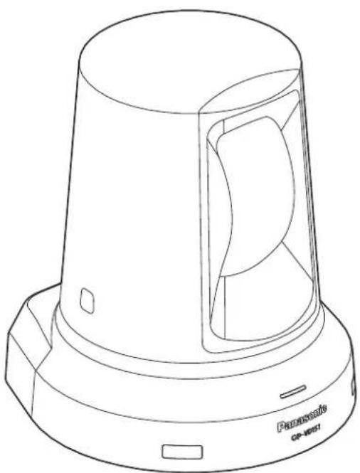
This appliance is supplied with a moulded three-pin mains plug for your safety and convenience. Should the fuse need to be replaced, please ensure that the replacement fuse is of the same rating and that it is approved by ASTA or BSI to BS1362.
Check for the ASTA mark or the BSI mark on the body of the fuse.
If the plug contains a removable fuse cover, you must ensure that it is refitted when the fuse is replaced. If you lose the fuse cover, the plug must not be used until a replacement cover is obtained. A replacement fuse cover can be purchased from your local Panasonic dealer.
IF THE FITTED MOULDED PLUG IS UNSUITABLE FOR THE AC OUTLET IN YOUR PREMISES, THEN THE FUSE SHOULD BE REMOVED AND THE PLUG CUT OFF AND DISPOSED OF SAFELY. THERE IS A DANGER OF SEVERE ELECTRICAL SHOCK IF THE CUT-OFF PLUG IS INSERTED INTO ANY 13 AMP SOCKET.
How to replace the fuse:
Open the fuse compartment with a screwdriver and replace the fuse and fuse cover.
Safety precautions
We declare under our sole responsibility that the product to which this declaration relates is in conformity with the standards or other normative documents following the provisions of Directives 2006/95/EC and 2004/108/EC.
Concerning HD Visual Communications System 6
Concerning the wireless remote controller (optional accessory) 6
Trademarks and registered trademarks 6
About copyright and licence 6
Disclaimer of warranty 6
Characteristics 7
Accessories 8
Installation precautions 9
Operating precautions 11
Concerning the wireless remote controller (optional accessory) 13
Parts and their functions 14
Camera unit 14
Wireless remote controller (optional accessory) 16
Setting the remote control IDs 18
Installation 19
When installing the unit on a desk 19
When mounting the unit on a tripod 20
Connections 21
Connections with an HD Visual Communications System 21
Troubleshooting 22
Appearance 25
Specifications 26
How the model's Operating Instructions manuals are configured
- The manual of this HD communication camera (hereafter, "the unit") is divided into two manuals: one is the
(this manual), and the other is the .
Before installing the unit, be sure to read the
This manual explains how to install the unit.
For details on how to operate the unit and select its settings, refer to the "Operating Instructions
Download the "Operating Instructions
http://panasonic.net/psn/products/hdvc/resource/users_guide.html
To read PDF files, you will need Adobe Reader® which is available from Adobe Systems.
Overview
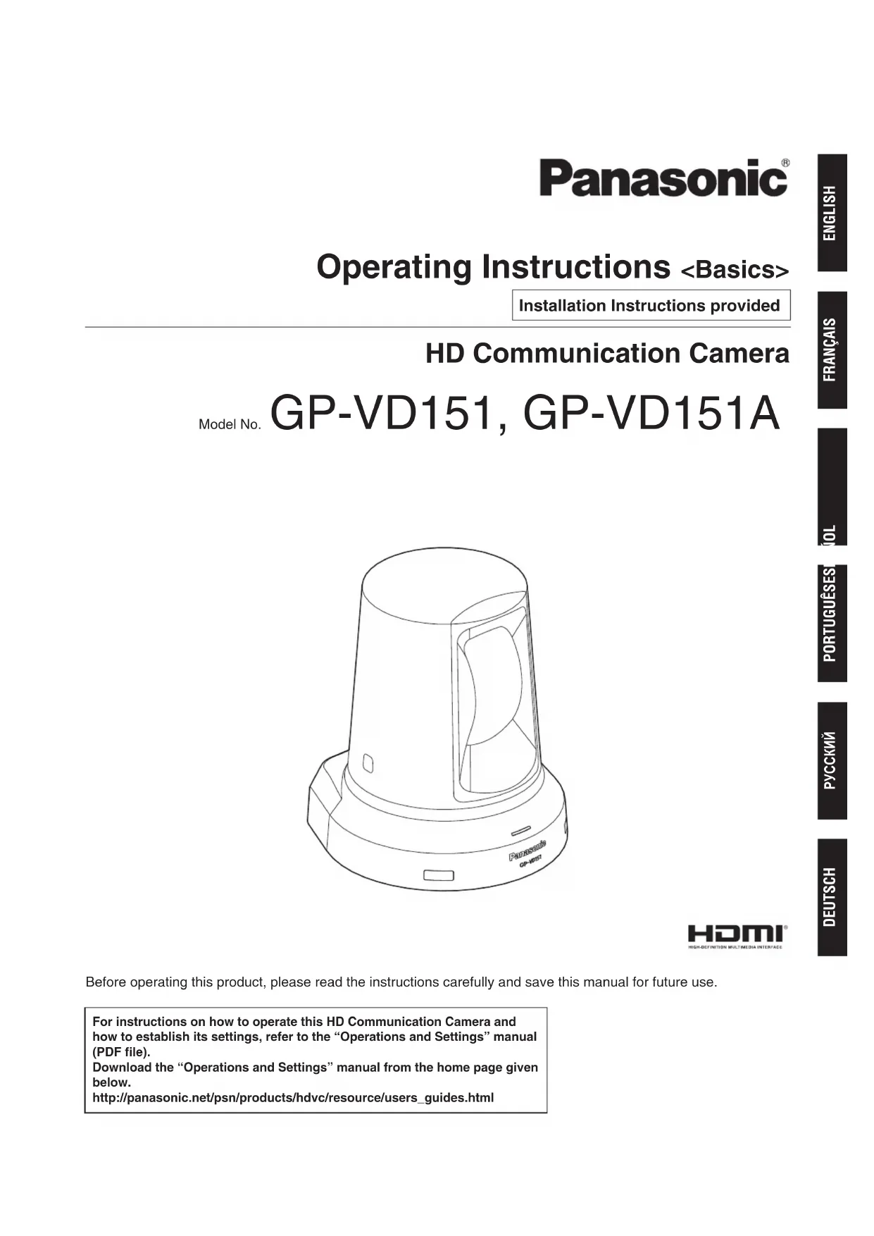
- This unit is a full HD camera integrated with a pan-tilt head and featuring a 1/2.8-type full HD CMOS sensor and digital signal processor (DSP).
- In addition to its optical 12 × zoom lens, the unit comes with a 10 × digital zoom to achieve high-quality shooting that overflows with ambiance.
- This unit is designed to be used exclusively with Panasonic HD visual communications system. Compatible HD visual communication units: KX-VC1300, KX-VC1600, KX-VC1300A, KX-VC1600A, KX-VC1300SX, KX-VC1600SX, KX-VC300NA, KX-VC300BX, KX-VC600NA, KX-VC600BX, KX-VC300CX, KX-VC300EX, KX-VC600CX, KX-VC600EX
■Concerning HD Visual Communications System
- For descriptions of the panning, tilting, zooming, preset and other camera operations using an HD visual communication unit, refer to the operating instructions of the unit which is supported.
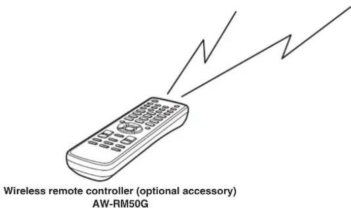
Concerning the wireless remote controller (optional accessory)
- This unit can be operated remotely using a wireless remote controller (model AW-RM50G) available as an optional accessory. It cannot be operated directly using the wireless remote controller of an HD visual communication unit. To purchase a wireless remote controller, contact your dealer.
Trademarks and registered trademarks
- HDMI, the HDMI Logo and High-Definition Multimedia Interface are trademarks or registered trademarks of HDMI Licensing LLC in the United States and other countries.
Adobe, Acrobat Reader, and Reader are either registered trademarks or trademarks of Adobe Systems Incorporated in the United States and/or other countries.
■About copyright and licence
Distributing, copying, disassembling, reverse compiling, reverse engineering, and also exporting in violation of export laws of the software provided with this unit are expressly prohibited.
Disclaimer of warranty
IN NO EVENT SHALL Panasonic Corporation BE LIABLE TO ANY PARTY OR ANY PERSON, EXCEPT FOR REPLACEMENT OR REASONABLE MAINTENANCE OF THE PRODUCT, FOR THE CASES, INCLUDING BUT NOT LIMITED TO BELOW:
① ANY DAMAGE AND LOSS, INCLUDING WITHOUT LIMITATION, DIRECT OR INDIRECT, SPECIAL, CONSEQUENTIAL OR EXEMPLARY, ARISING OUT OF OR RELATING TO THE PRODUCT;
② PERSONAL INJURY OR ANY DAMAGE CAUSED BY INAPPROPRIATE USE OR NEGLIGENT OPERATION OF THE USER;
③ UNAUTHORIZED DISASSEMBLE, REPAIR OR MODIFICATION OF THE PRODUCT BY THE USER;
INCONVENIENCE OR ANY LOSS ARISING WHEN IMAGES ARE NOT DISPLAYED, DUE TO ANY REASON OR CAUSE INCLUDING ANY FAILURE OR PROBLEM OF THE PRODUCT;
⑤ ANY PROBLEM, CONSEQUENTIAL INCONVENIENCE, OR LOSS OR DAMAGE, ARISING OUT OF THE SYSTEM COMBINED BY THE DEVICES OF THIRD PARTY;
(6) LOSS OF REGISTERED DATA CAUSED BY ANY FAILURE.
1/2.8-type CMOS sensor and high-performance 12× zoom lens featured
A 1/2.8-type full HD CMOS sensor and DSP (digital signal processor) are incorporated. High-quality pictures are obtained by video processing in many different kinds of ways.
- In addition to its optical 12 × zoom lens, the unit comes with a 10 × digital zoom to achieve high-quality images that overflow with ambiance.
- A dynamic range stretch (DRS) function that compensates for overexposure and loss of dark detail and a new hybrid digital noise reduction (Hybrid DNR) function for minimizing image lag even in dark locations and shooting scenes clearly are incorporated to reproduce clean and clear images in a wide range of applications.
Easy operation of unit enabled by its integration with a high-performance pan-tilt head unit
Operations at the high speed of 90^ / s
- Wide rotational angles with a panning range of ± 100^ and a tilting range of ± 30^
- Quiet operation with noise levels of NC35 (normal speed) and NC40 (when preset)
Use of easy-to-operate wireless remote controller (optional accessory) is possible
- A wireless remote controller capable of operating up to two units can be used.
It can easily be used to set the various functions or switch between them while viewing the menu screens.
Check that the following accessories are present and accounted for.
Operating Instructions
AC adapter 1
Power cable* (1.8 m {5.91 feet}) (GP-VD151) 4
Power cable* (1.8 m {5.91 feet}) (GP-VD151A) 1
- Use the power cable that is suited to your locality.
In addition to heeding the points presented in the "Safety precautions", observe the following precautions as well.
Ensure that the installation work complies with the technical standards governing electrical equipment.
This unit is for indoor use only.
It cannot be used outdoors.
Avoid installation in a location where the unit will be exposed to direct sunlight for extended periods or near a cooling or heating appliance.
Otherwise, deformation, discoloration, malfunctioning and/or problems in operation may result. Operate the unit where it will not be splashed or sprayed by water.
Use this unit on a flat and level surface.
Do not install the unit on the surface of a wall, on a ceiling or in a location where the unit will end up being inclined at an angle.
Note
- Do not hold the camera head while undertaking the installation work. Doing so may cause malfunctioning.

Concerning the installation location
Install the unit in a stable location which will not be susceptible to shaking. If the unit is installed in a location which is susceptible to shaking, this will cause the unit's images to shake in turn.
Install the unit after conferring in detail with your dealer.
Do not install or use the unit in the following kinds of locations.
- On the surface of a wall (where the unit will be installed sideways and/or where the unit will be secured to the wall using a mounting bracket)
- On a ceiling (where the unit would be installed so that it is pointing downward)
- In locations (including places such as under the eaves of a building) where the unit would be directly exposed to rain or water
- In locations such as kitchens where there are high concentrations of steam and grease
- In outdoor locations or hot places where the temperature will exceed 40^ 104^
- In cold locations where the temperature will drop below 0^ 32^
In locations where the humidity will exceed 85% - In locations where chemicals are used such as near swimming pools
- At sea, in coastal areas or in locations where corrosive gases are emitted
- In locations where radiation, X-rays, or strong radio waves or magnetic fields are generated
- In locations where the unit would be subject to a great deal of vibration such as on board a vehicle or ship (this unit is not designed to be used in vehicles)
- In locations where the temperature is subject to sudden changes such as near the air outlet of an air conditioner or near a door which allows the outside air to come in
What to avoid to ensure that the unit will perform stably over a prolonged period
- Using the unit for a prolonged period in a location with high temperature and humidity levels will cause its parts to deteriorate and shorten its service life.
- Ensure that a cooling unit or heating unit will not blow any air directly toward the installation location.
When the unit is no longer going to be used, do not leave it lying around, but be absolutely sure to dispose of it properly.
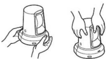
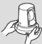
When installing, transferring or disposing of the unit, be absolutely sure to hold it by its pedestal area.
Problems may result if the camera head is held or rotated.
Do not attach a filter, hood, extender or other parts to the unit.
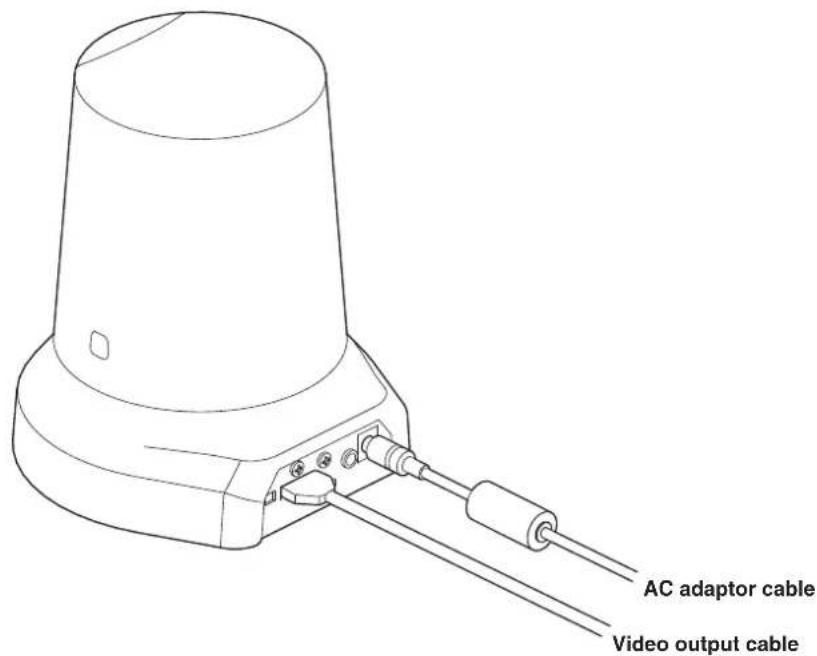
Use the dedicated AC adapter and power cable provided with the unit.
Connect the AC adapter and power cable to the power inlet securely.
The power cable supplied with this unit must always be used with this unit. The unit cannot be used with a power cable which is not supplied with the unit. Neither can the power cable supplied with the unit be used with any other device.
Installing the AC adapter
- Do not place the AC adapter in direct contact with a floor or any other such surface. An extreme danger is posed by water pooling on the surface as a result of leaking rainwater or some other reason.
Anchor the AC adapter securely to a surface on which no water, dust, etc. will collect.
- Secure the adapter firmly so that there will be no chance that it will fall off or fall down.
Secure it using a strength which can withstand the mass (approx. 320g {0.71 lbs.}) of the AC adapter.
Install the accessory AC adapter near the main power outlet, and position it in such a way that its power plug can be plugged into and unplugged from the outlet easily.
If the AC adapter is to be connected where dust collects, remove the dust and dirt from the power plug at regular intervals as a measure to prevent tracking.
Power switch
This unit does not have a power switch. The power turns on when its power plug is connected to a power outlet. When the power is turned on, the pan, tilt, zoom and focusing operations are performed. Before proceeding with maintenance, be absolutely sure to disconnect the power plug from the power outlet.
Connecting the power cable
Be absolutely sure to connect the power cable of the AC adapter through a circuit breaker using one of the following methods.
(1) Connect the power cable through a power control unit.
(2) Connect the power cable to a circuit breaker in a power distribution panel with a contact distance of 3.0mm or more.
Use a circuit breaker which is capable of shutting off all the poles of the main power supply with the exception of the protective ground conductor.
(3) Install the AC adapter near the power outlet, and connect it through the power plug.
If there is a possibility of noise interference
Either wire the cables so that the power cable (ceiling light cord) of AC 100V or more, and the signal cable are placed at least 1 m {3.3 feet} apart. Alternatively run each cable through its own metal conduit. (The metal conduits must be grounded.)
Radio signal interference
If the unit is positioned near a TV or radio transmitting antenna or a strong electrical field or magnetic field (such as that generated by a motor, transformer or power lines), its images may be distorted and/or the images may be affected by noise.
When connecting the cables, ensure that the connector areas will not be subject to any load.
Doing so may cause malfunctioning.
Allowing the generated heat to escape
This unit allows the heat generated inside to escape from its surfaces.
Do not install the unit in a location where it will be surrounded by walls or other surfaces and where heat will be trapped. In addition, the heat is dissipated to the bottom panel which will warm up over time: This is normal and not indicative of any trouble.
IMPORTANT
- The product name and its electrical ratings are marked on its bottom panel.
Shoot under the proper lighting conditions.
To produce pictures with eye-pleasing colors, shoot under the proper lighting conditions.
The pictures may not appear with their proper colors when shooting under fluorescent lights.
Select the proper lighting as required.
To ensure a stable performance in the long term
Using the unit for prolonged periods in locations where the temperature and humidity levels are high will cause its parts to deteriorate, resulting in a reduction of its service life.
(Recommended temperature: Max. 35^ 95^ )
Ensure that a cooling unit or heating unit will not blow any air directly toward the installation location.
Image persistence on the CMOS sensor color filters
If parts of the CMOS sensor are exposed continuously to spotlights or other bright lights, the color filters inside the CMOS sensor will deteriorate, and the parts concerned may become discolored. The discoloration may be noticeable when the direction of fixed monitoring is changed.
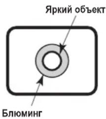
Do not point the camera at strong lights.
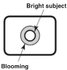
When parts of the CMOS sensor are exposed to spotlights or other strong lights, blooming (a phenomenon where the edges of strong lights become blurred) may occur.
Concerning the color reproduction of CMOS sensors
Depending on the color tones of the subjects, the color reproduction may deteriorate: This is normal and not indicative of any trouble.
What happens with high-brightness subjects
Flare may occur if an extremely bright light source is pointed at the lens. In a case like this, change the angle or take some other remedial action.
When using the automatic functions
- If "FullAuto" has been selected as the setting for Scene on the camera menu, for example, all the auto settings will be turned on, and manual operations will no longer be possible for some of the items.
- When using the ATW (auto tracking white adjustment) function under fluorescent lights, the white balance may vary.
- In some situations, it may be hard to focus at the auto setting. In cases like this, select the manual setting, and focus manually.
- The appropriate brightness may not be obtained when shooting bright objects using the auto settings for the gain and iris. In cases like this, set the shutter speed to manual, and adjust.
Zooming and focusing
When the focus is set manually, out-of-focusing may occur during zooming.
After zooming, if necessary, either adjust the focus or set the focus to auto.
When using the focus at the manual setting, proceed with zooming after setting the focus position at the Tele end where the focusing accuracy is higher.
(However, if the distance from the unit to the subject is less than 1.5m {4.92 feet}, the subject may shift out of focus at the Wide end.)
If zooming is performed to the Tele end after having adjusted the focus at the Wide end, out-of-focusing may occur.
Concerning the zoom position when the power is turned on
When the unit's power is turned on, the zoom, focus and iris return to the positions they occupied immediately before the power was turned off. (This happens for the focus and iris when they were set manually.)
However, this position may not be restored if, for instance, the power cable was disconnected during operation.
Operating temperature range
Avoid using the unit in cold locations where the temperature drops below 0^ 32^ or hot locations where the temperature rises above +40^ 104^ since these temperatures downgrade the picture quality and adversely affect the internal parts.
Concerning the HDMI interface standard
This unit has been certified as HDMI-compatible, but on rare occasions images may not be displayed depending on the HDMI device which has been connected to the unit.
Turn off the power before connecting or disconnecting the cables.
Always be sure to turn off the power before connecting or disconnecting the cables.
Operating precautions
Handle the unit carefully.
Do not drop the unit or subject it to strong impact or vibration. Doing so may cause the unit to malfunction.
When the unit is not in use
Turn off the unit's power when it is not in use.
When the unit is no longer going to be used, do not leave it lying around, but be absolutely sure to dispose of it properly.
Do not touch the optical system parts.
The optical system parts are the very heart of the camera. Under no circumstances must they be touched.
In the unlikely event that they have become dusty, remove the dust by using a camera blower or by wiping them gently with a lens cleaning paper.
Do not allow foreign matter to make contact with the rotating parts.
Otherwise, trouble may be caused.
Keep the unit away from water.
Avoid all direct contact with water. Otherwise, problems may occur.
Maintenance
Turn off the unit's power before proceeding with maintenance.
Otherwise, you may injure yourself.
Wipe the surfaces using a soft dry cloth. Avoid all contact with benzine, paint thinners and other volatile substances, and avoid using these substances. Otherwise, the casing may become discolored.
Do not turn the camera head by hand.
Turning the camera head by hand may cause the unit to malfunction.
Use the unit in an environment with minimal moisture and dust.
Avoid using the unit in an environment with high concentration of moisture or dust since these conditions will damage the internal parts.
Disposal of the unit
When the unit has reached the end of its service life and is to be disposed of, ask a qualified contractor to dispose of the unit properly in order to protect the environment.
Concerning the wireless remote controller (optional accessory)
This unit can be operated by remote control using a wireless remote controller (model number: AW-RM50G) which is sold separately.
The unit cannot be operated directly using the wireless remote controller of an HD visual communication unit. Check out the following points before using the wireless remote controller.
Consult your dealer concerning the purchase of a wireless remote controller.
- Operate the wireless remote controller from positions less than 6 m {19.7 feet} away from the unit.
- The wireless remote controller may not work when it is pointed from certain angles at the unit.
From a place where the wireless remote controller signal light-sensing area (hereafter, "light-sensing area") can be seen, point the signal transmission window of the wireless remote controller at the light-sensing area, and operate the buttons.
It may prove to be more difficult to operate the unit when the remote control is operated from behind the unit.
- If the unit is installed near fluorescent lights, plasma monitors or other such products or if the unit is exposed to sunlight, the effects of the light may make it impossible for the unit to be operated using the wireless remote controller.
Be sure to follow the steps below for installation and use.
- Take steps to ensure that the light-sensing area will not be exposed to the light from fluorescent lights, plasma monitors or other such products or from the sun.
-
Install the unit away from fluorescent lights, plasma monitors and other such products.
-
For about 10 minutes even after the batteries have been removed from the wireless remote controller, the selection of the operation to be performed (the [CAM1], [CAM2], [CAM3] or [CAM4] button which was pressed last) will remain stored in the memory. When a longer period of time elapses, however, the selection is reset to the status established when the [CAM1] button was pressed.
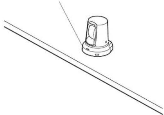
Camera unit
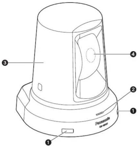
Wireless remote controller signal light-sensing area
Light sensors are located in two places at the front of the camera pedestal.
Status display lamp
This lights in the following way depending on the status of the unit.
Orange: When the standby status is established
Green: When the power is on
Red: When trouble has occurred in the unit
Green and blinks twice:
When a signal matched by the remote control
ID has been received from the wireless remote controller (optional accessory) with the power is on
Orange and blinks twice:
When a signal which is not matched by the remote control ID has been received from the wireless remote controller (optional accessory) while the power is on
3 Camera head
This rotates in the horizontal direction.
Lens unit
This rotates in the up and down direction.
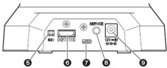
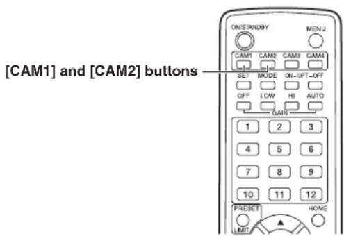
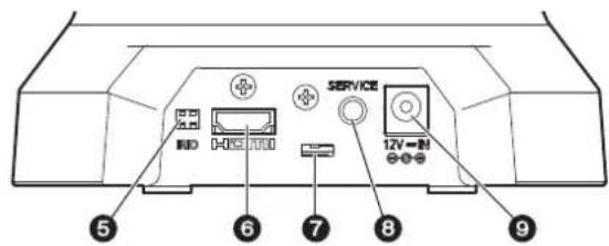
IR ID switches [IRID]
| [CAM1] [CAM2] | |
| IRID | IRID |
These are used to select the ID of the wireless remote controller (optional accessory).
The IR ID switch settings "CAM1" and "CAM2" correspond to the [CAM1] and [CAM2] buttons on the wireless remote controller.
HDMI connector [HDMI]
This is the HDMI video output connector.
7 Anti-theft wire mounting hole
Use this hole to attach the wire bracket.
Service connector
This connector is used only when maintenance is carried out.
DC IN connector [12V=TN

Connect the AC adapter supplied with the unit to this connector to supply the DC 12 V voltage to the unit.
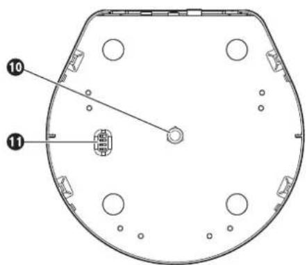
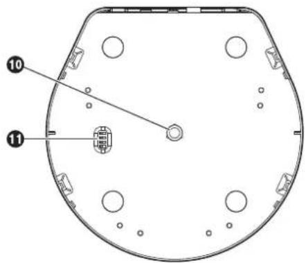
Threaded hole (thread: 1/4-20UNC) for mounting the camera
Use this hole when mounting the camera on a tripod, etc.
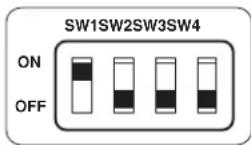
Service switches

Normally, set all switches in the "OFF" position for use.
To change the recording format, change the settings to the following positions, then turn off the power and turn it back on again.
For details on how to change the recording format, refer to "Changing the format" (in the
■ Wireless remote controller (optional accessory)
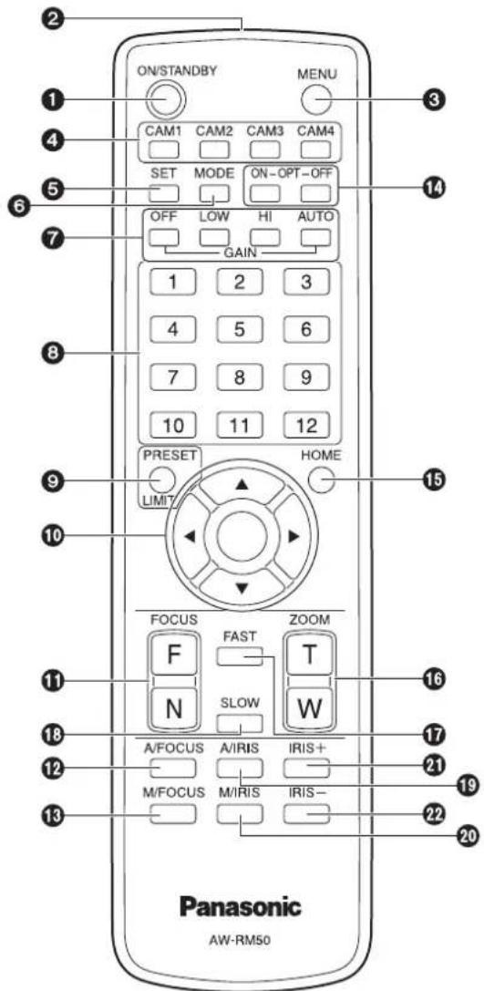
ON/STANDBY button
Each time this is pressed for at least 2 seconds, operation switches between turning on the unit's power and establishing the standby status.
Notes
- When operation is transferred to the STANDBY mode: The current pan-tilt position is stored in the memory (as a POWER ON preset), and the camera moves so that it points toward the back.
- When operation is transferred to the POWER ON mode: The camera moves to the position which was stored in the memory (as a POWER ON preset) when operation was transferred to the STANDBY mode.
2 Signal transmission window
3 MENU button
Each time this is pressed for at least 2 seconds, operation switches between displaying the unit's menu and exiting the menu.
When it is pressed quickly (for less than 2 seconds) while a menu is displayed, the setting change is canceled.
4 CAM1 to CAM4 buttons
These are used to select the units that are to be operated.
Once a button has been selected, the unit corresponding to the selected button can be operated.
To operate this unit, use "CAM1" or "CAM2".
SET button
If this button is pressed when one of the "Manual1 to 3" settings has been selected for "Scene" on the camera menu and the AWB A memory or AWB B memory has been selected by the white balance adjustment, the white balance is automatically adjusted and registered in the selected memory.
MODE button
This is used for future expansion of the functions.
It is not used at the present time.
7 GAIN buttons [OFF] [LOW] [HI] [AUTO]
These are used to set the gain.
The gain increase can be set in three steps using the [OFF], [LOW] and [HI] buttons.
[LOW] is set to 9 dB, and [HI] is set to 18 dB.
When the [AUTO] button is pressed, the AGC function is activated, and the gain is adjusted automatically depending on the light quantity.
The maximum gain of the AGC function can be set using the menu.
3 Preset memory call buttons [1] to [12]
These are used to call the information on the unit's directions and other settings, which have been registered in the unit's preset memories No.1 to No.12, and reproduce those settings.
PRESET/LIMIT button
This is used to register the settings in the preset memories.
When a preset memory call button is pressed while the PRESET/LIMIT button is held down, the information on the unit's current direction and other settings is registered in the call button.
Preset memory call buttons [1] to [12] correspond to the unit's No.1 to No.12 preset memories.
Pan-tilt buttons and menu operation buttons
[△][▼][<][>][○]
(1) These are used to change the unit's direction. The unit is tilted in the up/down direction using the [▲] and [▼] buttons and panned in the left/right direction using the [▲] and [▼] buttons.
The [O] button does not work during tilting and panning.
When the [ ] or [ ] and [] or [ ] buttons are pressed at the same time, the unit moves diagonally.
(2) The buttons are used for menu operations when the unit displays the menus.
Use the [ ],[ ],[ ] and [ ] buttons to select the menu items.
When a selected item has a sub-menu, the sub-menu will be displayed by pressing the [O] button.
When the cursor is aligned with a particular item and the [O] button is pressed on the setting menu at the bottom hierarchical level, the setting of the selected item blinks.
When the [ ] button is pressed after the setting has been changed using the [ ],[ ],[ ] and [ ] buttons, the setting stops blinking, and the new setting is entered.
With a regular menu, the new setting is reflected immediately after it has been changed if the change was made from the setting in the blinking status, but there are some menus (Scene, Format and Initialize) where it is reflected only after the [O] button has been pressed, the blinking has stopped and the new setting has been entered.
If the MENU button is pressed quickly (for less than 2 seconds) while the setting is in the blinking status, the change will be canceled, and the setting selected prior to the change will be restored.
FOCUS buttons [F] [N]
These are used to adjust the lens focus manually when the manual setting is established for the lens focus.
The focus is adjusted in the far using the [F] button and in the near using the [N] button.
A/FOCUS button
This is used when automatically adjusting the lens focus.
M/FOCUS button
This is used when manually adjusting the lens focus. The FOCUS buttons ([F] and [N]) are used when performing the actual adjustment.
14 OPT buttons [ON] [OFF]
These are used for future expansion of the functions. They are not used at the present time.
HOME button
When this is pressed for at least 2 seconds, the unit's direction (panning or tilting) returns to the reference position.
16 ZOOM buttons [T] [W]
These are used to adjust the lens zoom.
The zoom is adjusted in the wide-angle using the [W] button and in the telephoto using the [T] button.
FAST button
This is used to change the movement speed at which the panning, tilting, zooming and focusing operations are performed to the high speed.
Note
- The operating speed for panning and tilting when the preset memory settings have been called can be changed using the Preset Speed item of the camera menu.
SLOW button
This is used to change the movement speed at which the panning, tilting, zooming and focusing operations are performed to the low speed.
19 A/IRIS button
This establishes the setting for adjusting the lens iris automatically in line with the light quantity.
M/IRIS button
This establishes the setting for adjusting the lens iris manually.
The IRIS + and IRIS - buttons are used when performing the actual adjustment.
IRIS ^+ button
This is used to adjust the lens iris in the opening direction.
IRIS - button
This is used to adjust the lens iris in the closing direction.
The wireless remote controller (optional accessory) is capable of operating up to two units.
Set the remote control IDs for the units to enable the operation of each unit when the [CAM1] or [CAM2] button of the wireless remote controller is pressed.
- When using a multiple number of units, set a different remote control ID for each unit.
You cannot set the remote control IDs for this unit to "CAM3" or "CAM4".
- When using one unit, set the remote control ID to "CAM1" unless the setting needs to be changed.
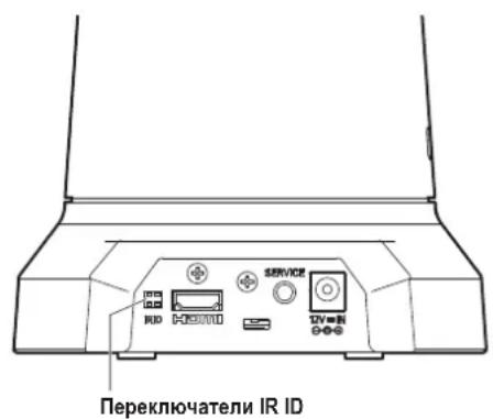
Setting procedure
Operate the IR ID switch on the units rear panel, and select "CAM1" or "CAM2" as the remote control ID. (See page 14)
The IR ID switch settings "CAM1" and "CAM2" correspond to the [CAM1] and [CAM2] buttons on the wireless remote controller.
(The factory setting is "CAM1").

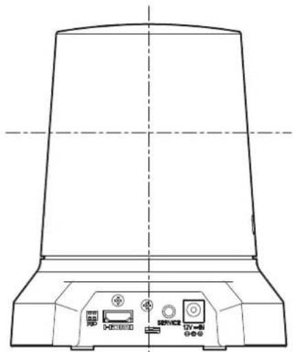
1 Connect the rear panel connectors.
When installing the unit on a desk
Place the unit flat on the surface.
Notes
- Install the unit in a stable location which will not be susceptible to shaking. If the unit is installed in a location which is susceptible to shaking, this will cause the unit's images to shake in turn.
Take care not to allow the unit to fall or otherwise be damaged during installation. - When carrying the unit, do not hold it by its head.
- Do not take hold of the camera head or rotate it. Doing so may cause malfunctioning.
- Take care not to pull the connected cables. Doing so may cause the unit to fall and/or it may result in injury.
Ensure that the unit will not fall off.
OKNG
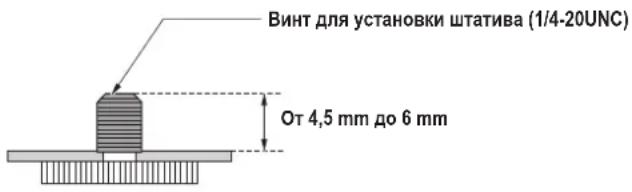
■When mounting the unit on a tripod
Use a highly stable tripod which can bear the weight of the camera mounted on it.
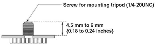
Attach the tripod to the threaded hole for mounting the camera on the camera's bottom panel.
Place the tripod on a completely flat and level surface.
Tighten the screw by hand to mount the tripod securely. Do not tighten the screw by rotating the camera body. Doing so may cause malfunctioning. Use screw for mounting the tripod that satisfy the following standard.
Notes
- Do not install the unit where people will be passing back and forth.
- When using the unit mounted on a tripod, do not put the tripod high above the floor level.
- Mount the unit securely so there is no looseness. Looseness may cause the unit to fall off and/or result in injuries.
- When the unit is going to be used for a prolonged period of time, take steps to ensure that the unit will not topple or fall over and that it will not fall off or fall down. After using the unit, restore the installation location to its original state without delay.
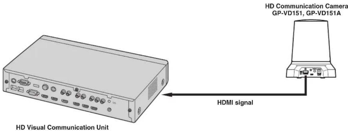
Connections with an HD Visual Communications System
- For descriptions of the panning, tilting, zooming, preset and other camera operations using an HD visual communication unit, refer to the operating instructions of the unit which is supported.
Operation
| Symptom Cause and remedial action | Reference pages | |
| No power | ● Is the AC adapter securely connected to the AC outlet? — | |
| ● Is the power plug of the AC adapter connected properly? — | ||
| ● When the unit is being operated by the wireless remote controller → Also refer to the “Cannot operate using the wireless remote controller” item. | — | |
| Cannot operate (commento wireless remote controller, HD Visual Communication Unit) | ● Is the power on? → If the unit's status display lamp is off or if it has lighted up orange, it means that the unit's power is not being supplied. | <Operations and Settings> |
| ● Has the correct unit to be operated been selected? | <Operations and Settings> | |
| Cannot operate using the wireless remote controller | ● Have the remote control's batteries run down or have the batteries been installed with their polarities reversed? → If the status display lamp does not blink even when the wireless remote controller is operated near the wireless remote controller signal light-sensing area, it means that the batteries have run down. Replace the batteries. | — |
| ● Is there a fluorescent light or plasma monitor near the unit and, if so, is the wireless remote controller signal light-sensing area exposed to its light? | P.13 | |
Video
| Symptom Cause and remedial action | Reference pages | |
| No pictures are displayed or the pictures are disturbed | ·Has the unit been connected properly to the other connected devices? | P.21 |
| ·If the system is configured in such a way that the picture is also switched when the unit to be operated is selected, has the correct unit been selected? | <Operations and Settings> | |
| ·Has the video signal setting been selected correctly? | <Operations and Settings> | |
| The menu screen is displayed | ·Exit the menu. | <Operations and Settings> |
| It is difficult to view the menu screens | ·Depending on the HDMI monitor you are using, you may experience one or more of the symptoms described below. ·The resolution of the characters in the menu displays changes as the background image changes. ·Depending on the edge enhancement setting established for the monitor, white lines appear in front of the black shadows of the menus. ·Depending on the edge enhancement setting established for the monitor, the background colors may be superimposed onto the white parts of the menus. | — |
| No auto focusing | ·Is the focus set to manual? →Auto focusing is initiated as soon as the focus is set to auto. | <Operations and Settings> |
| ·In some situations, it may be hard to focus at the auto setting. →In cases like this, select the manual setting, and focus manually. | <Operations and Settings> | |
| The subject is not brought into focus during zooming when the manual setting is used for the focus | ·Was the focus adjusted at the Tele end? →First adjust the focus at the Tele end where the focusing accuracy is higher, and then proceed with the zooming. | — |
| ·Under some operating conditions, it may be hard to bring subjects into focus. →In such cases, use the focus at the auto setting. | <Operations and Settings> | |
| Ring-shaped reflections appear in the four corners of the images | ·These are caused by the reflections of the light between the lens and the cover in front of the lens. Find a way of optimizing the position of the lighting relative to the position of the unit, and install and use the unit in a location where the reflections will not occur. | — |
| Something is wrong with the coloring of the pictures | ·Activate the ATW (Auto tracking white adjustment) function. | <Operations and Settings> |
| ·In some situations, the proper colors may not be reproduced using the ATW function. →In cases like this, proceed with the white balance adjustment. | <Operations and Settings> | |
| The pictures are too light or too dark | Either select the auto setting for the iris or select the manual setting and adjust the iris manually. | <Operations and Settings> |
| The pictures may be dark if the video signal cables are too long because this will cause signal attenuation. | — | |
| The subjects appear distorted | If a subject has suddenly crossed in front of the camera, it may appear slightly distorted because this camera uses a CMOS image sensor. This is normal and not indicative of any problem. | — |
| When the flash is fired during shooting, only the top or bottom of the screen becomes lighter | With a CMOS image sensor, the shooting timing differs slightly between the top left and bottom right of the screen. This means that when the flash is fired, the bottom of the screen will become lighter in the field concerned and the top will become lighter in the next field. This is normal and not indicative of any problem. | — |
| The brightness changes cyclically or the colors change, and horizontal stripes can be seen passing across the screen | These phenomena (flicker) may occur under the illumination produced by fluorescent lighting, mercury bulbs or other types of discharge tubes. This is normal and not indicative of any problem. At a time like this, it is recommended that the electronic shutter speed be set to 1/120 in areas with a 60 Hz power line frequency or to OFF in areas with a 50 Hz power line frequency. | <Operations and Settings> |
| When fine lines or cyclical patterns are shot, flickering is seen or coloring is added to them | This phenomenon occurs because the pixels are arranged systematically on each image sensor. It is noticeable when the spatial frequency of a subject and the pixel pitch are brought into proximity so change the camera angle or take other such action. | — |
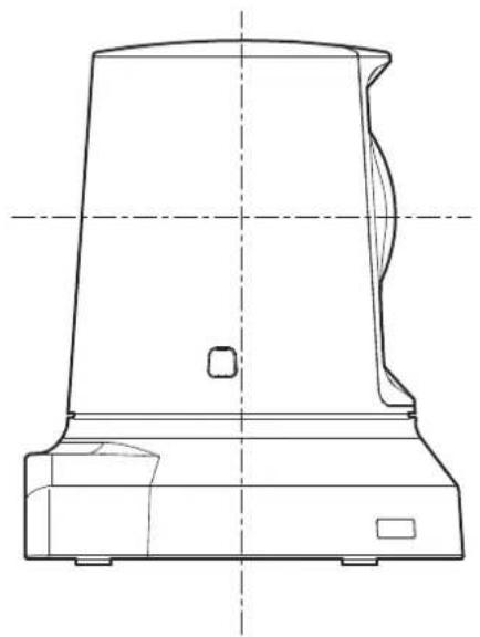
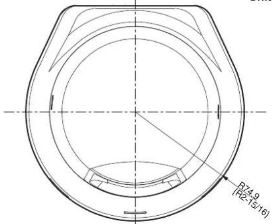
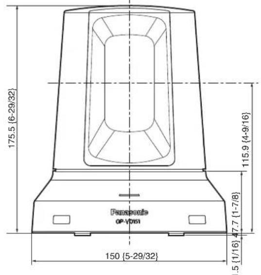
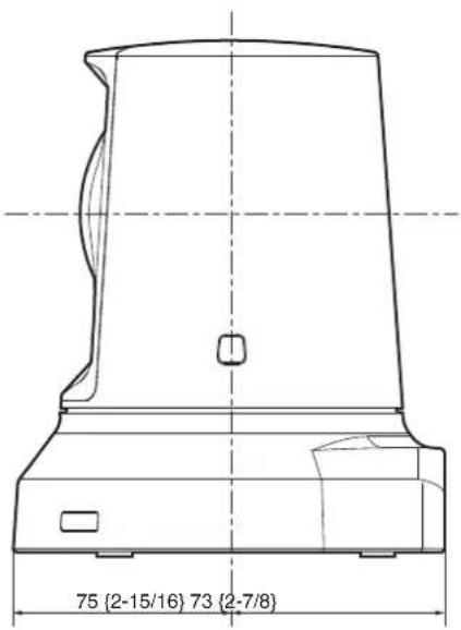
Unit: mm {inch}
Power requirements:DC12V±10% (AC adapter provided)
Power consumption: 1.0 A
indicates safety information.
GENERAL
Ambient operating temperature:
0^ to +40^ +32^ to +104^
Storage temperature: -20^ to +50^ -4^ to +122^
Allowable humidity ranges:
20% to 90% (no condensation)
Mass: Approx. 1.2kg {2.65 lbs.}
Dimensions (× × )
150× 148× 177mm
5-29/32 inches × 5-13/16 inches
6-31/32 inches}
Finish: Silver
INPUT
Input connector: DC 12 V IN
OUTPUT
Video output: HDMI (HDMI connector)
FUNCTIONS AND PERFORMANCE
[Camera unit]
Imaging sensors: 1/2.8-type Full-HD CMOS
| Lens: | Motorized 12× zoom, f/1.6 to 2.0 (f=4.7 to 56.4 mm; 35 mm equivalent: 36.9 mm to 442.8 mm) |
Focus: Switching between auto and manual
| Focus distance: | Entire zooming range: |
| 1.5 m {4.9 feet} | |
| Wide end: 30 cm {0.98 feet} |
Color separation optical system:
On-chip color filter system
Minimum illumination: 3lx (50IRE, F1.6, +36 dB)
Horizontal resolution: 850 TV lines Typ (Center area)
| Gain selection: | Auto, 0 dB, 3 dB, 6 dB, 9 dB, 12 dB, 15 dB, 18 dB |
Storage mode: 0 dB, 6 dB, 12 dB, 18 dB
Electronic shutter speed:
Step: 1/100, 1/250, 1/500, 1/1000
1/2000, 1/4000, 1/10000
Synchro scan: 60.24 Hz to 646.21 Hz
| Gamma: | Off, Normal (Low, Mid, High), Cinema |
White balance: AWB A,AWB B,ATW
Chroma amount variability:
7 levels variability
| Scene file: | FullAuto, Manual1, Manual2, Manual3 |
Output format: HD 1080:59.94p
HD 1080:59.94i
HD 1080:29.97p
HD 720:59.94p
SD 480:59.94p
[Pan-tilt head unit]
Pan/tilt operation speed:
Max. 90^ /s or more
Panning range: ±100°
Tilting range: ±30°
- Depending on the pan or tilt position, the camera may be reflected in the image.
Quietness: NC35 (normal speed), NC40 (when preset)
AC adapter
[PGLV1009]
| Input: | AC 100 V to 240 V, 1.2 A to 0.6 A, 50 Hz/60 Hz |
Output: DC 12 V, 2.0 A
[PGLV1015]
| Input: AC 100 V to 240 V, 0.5 A to 0.3 A, 50 Hz/60 Hz |
Output: DC 12 V, 1.5 A
■ Optional accessories
Wireless remote controller AW-RM50G (Manufactured by Panasonic)
(Size "R6" or "LR6" dry battery × 2 obtained separately)
Mass and dimensions shown are approximate. Specifications are subject to change without notice.
VERSION FRANÇAISE
(FRENCH VERSION)
ELECTRIQUES NE PAS OUVRIR

ATTENTION: AFIN DE PREVENIR LE RISQUE DE CHOCS ÉLECTRIQUES, NE PAS RETIRER LES VIS. Toute réPARATION DEVRAIT ÉTRE CONFIEE À UN PERSONNEL QUALIFIÉ.

http://panasonic.net/psn/products/hdvc/resource/users_guide.html
16 Touches ZOOM [T] [W]
Gamma: Off, Normal (Low, Mid, High),
Cinema
Balance des blancs: AWB A, AWB B, ATW
Gamma: Off, Normal (Low, Mid, High), Cinema
Salida: 12 V CC, 2,0 A
[PGLV1015]
Entrada: 100 V a 240 V CA, 0,5 A a 0,3 A, 50 Hz/60 Hz
Salida: 12 V CC, 1,5 A
(PORTUGUESE VERSION)
Definir as IDs do controlo remoto 18
Instalacao 19
Quando instalar a unidad numa secretaria 19
Quandomontarauuniduadum tripé 20
Ligaoes 21
Ligaoes com umsystema de comunicaoes video HD 21
Resolucao de Problemas 22
Aspecto 25
Especificações 26
http://panasonic.net/psn/products/hdvc/resource/users_guide.html
Para ler ficheiros PDF, necessitará do Adobe Reader que está disponible na Adobe Systems.
■ Descrição geral
Gama: Off, Normal (Low, Mid, High), Cinema
Equilibrio de blancos:AWB A,AWB B,ATW
Saida: 12 V CC, 2,0 A
Entrada: 100 V a 240 V CA, 0,5 A a 0,3 A, 50 Hz/60 Hz
Saïda: 12 V CC, 1,5 A
KOMHOENTbI INxФyHKcIMn 13
Bnok Kamepb1 13
Nyt dntaHnHOHOro ynpabHeHHA (DonoHnTeIbHbIakceccyap) 15
YCTAHOBKa IeHTnΦnKaTOPOB nyIbTa
IcTahUHOHHoro ynpabHeHna 17
YcTaHOBka 18
Pn yctahOBke yctpoiCTBa Ha CTone 18
Pn yctahOBKe yctpoiCTBa Ha uTaTINB 19
CoeHHHeHn 20
IoiKIOUeHne K cIcTeMe HD BnDeo KOhFepEnu-CB3n 20
Ponck u yctpaHHe HeNCnPaBHOCTeI 21
Bheunn Bnd 24
Texnueckne xapaKtepcntkn 25
Kak coctabJIeHbI HNCTpyKcII N O 3KcNlyatauN DaHHoM oMeIi
PykoBocBO no daHHO Kamepe BbICOKO rpoa3peuHn DnKoHpeHc-CB3n (BdaNbHeHwem "yCTPOIcBO") nOppa3dienrTaHaDBe HNCTpykU:
B D aHOM pykoOCTBe o6brcnTc npoueDpya yctahOBKn yctpoiCTBa. Kpome TOrO, nIyEnn IOnIOHNteBbHex CbeHn O6 npabHeHn yctpoCTBOM N Bbl6pe Hactpoek 6paTneCk Jokyment "NCHpyKnno 3Kcnnyatau<Onepauu n yctahOBKn" (paIIN PDF). 3arpy3nte Dokyment "NCHpyKnno no 3Kcnnyatau<Onepauu n yctahOBKn" c npnbEHHo Hnke domaHne ctpaHnBu. http://panasonic.net/psn/products/hdvc/resource/users_guide.shtml
Jnry tHn PAnob PDF noHaobntc nporpamma Adobe Reader, kToPra noctabnTc komnaHne Adobe Systems.
■Obunie cBeDeHnA
- DAnHoe yctpoIcTBo IyBnIeTcra HHTerpnpObaHHo KaMepo BbCOKoro pa3peuHenn full HD c naHopamHo-HaKnIOHHo rONBOKo, B KOTOpOM BnepBbIe nCnONb3OBaH 1/2,8-dmMOBbIK M0N-DaTHNK full HD n CnFpObo CNrHaNbbl npOceccop (DSP).
B DOnONHeHnK ONTNUeCKOMy OBeKtNBcYbEInuHHeM 12X B yctpoiCTBE npDyCMTOpeHO uNpPBOe MaCtABnpoBaHne 10X dIgIOCTNXeHnB YoBCOKO KauCTBa CbEMKn, PpeDaHOe Bce DetaIN OkpyKaIOUe Cpebl.
-ДанhoeуctpoiCTBOpa3pa6oTaHOДПЯИСПОЛБ3OBAHIN NCKIIOHTeJIbHO CcIcTeMoH HD BIneo KOHΦepeHu-CB3H Panasonic. CoBmecTmblye yctpoiCTBa HD BIneo KOHΦepeHu-CB3H: KX-VC1300,KX-VC1600,KX-VC1300A,KX-VC1600A, KX-VC1300SX,KX-VC1600SX,KX-VC300NA, KX-VC300BX,KX-VC600NA,KX-VC600BX,KX-VC300CX, KX-VC300EX,KX-VC600CX,KX-VC600EX
HOpMaunOcnTeMaxHDBnDeo KOHpepeHu-CB3N
-Дя nonyuHЯ onIcaHи onepaun noBopoTa,HaKHOHa, TpaHCFOkaUH, BbINONHeHn IpeBaPntbHbIX yCTaHOBOK IN dpynx onepaun kamepbic nOMOuBo CnCTeMbl HD bIndeo KOHcpeHc-CBA3n ObaTneCb K NHCtpyKUnn NO 3KcNpyataun NoDdepxNBaEMOrO yctpoCTBa.
HOpMaun O npIbTe DnCTaHcNHOHorO ynpabJeHnA (DOnOHHTeHbHbI akceccyap)
- YnpabTb DaHbIM yCTpoCTBOM MOXHO nCTAHNOHO C NOMObIyNbTa DCtAHUHOY npabHeHn (MOeNB AW-RM50G), KOtpbI dOcTyne B KaueCTBe DOnOHHTeHBO akceccyapa. YnpabTb ycTPOCTBOM HENOCpeDCTBEHHo C NOMObIO NybTa DCtAHUHOrO npabHeHn DnCteMb HD BnDeo KOnpepeHu-CB3n HeBO3MOxHO. Dn npno6pTeHn NybTa DCtAHUHOrO npabHeHn 6paTInTeC b K dInepy.
Toprobbie 3HaKn 3apernctpnpoBaHHbIe Toprobbie 3HaKn
HDMI, norotin HDMI u High-Definition Multimedia Interface RbIIOCTO BApHbIMn 3HaKaAMN NIN 3apeRcTpuPOBaHHbIMn TOBapHbIMn 3HaKaAMN HDMI Licensing LLC B CoeDInHeHHbIX UToTaX AmePknu n Dpynx cTpaHax.
- Adobe, Acrobat Reader n Readerявсяков
3apernctpnoBaHbIMn TOBapHBIMn 3hakamn nIN TOBapHBIMn
3hakamn Adobe Systems Incorporated B CoeHHeHHbx IITatax
Amepnk n/In npnx cTpaHax.
06 abtopckom npaBe n IInceH3nn
PacnpoctpaHHe, KOHpOBaHne, n3accem6bnpoBaHne,
dekOMnIyIaI, peHHKInHpIHr, a TaKKe 3KcNopt B HapUeHne
3aKOHob 63KcNopTe npOrpaMMHO oOecneHnra, noCTabJIreMoro C
daHHbIM yCTpoIcTBOM, KaTEROpuYeCKn 3anpeSeHo.
OTka3 OT rapaHTm
HIN B KAKNX CJUYARX, KPOME 3AMEHbI INN OBOCHOBAHHO TEXOBCJLYKBAHNA IPOyKA, Panasonic Corporation HE HECET OTBETCTBEHHOCHTN IPEED IIOBOI CTOPOHIO INI JINLOM 3A CJUYAN, BKJIQUAY, HO HE OPGAHIBARc 3TIM:
① BCRAKOE IOBPEKJDEHNE I NOTEPN, BKJIIOUAOUUEBE3 OPGAHUHEHNA, HENOCPEICTBEHHBIE INIINKOCBEHHBIE, CIELNIAJBHBIE, NIOBOUYHIE INIINTINOBBIE, BO3HNKAIOUINE I3 INIIN OTHOCEIUEKDAHHOMY N3DEJIIO;
② TPABMbI ININ JIOBOE NOBPEXJEHNE, Bbl3bIBAEMbIE HECOOTBETCTBYOUJIM INPIMHEHENEM ININ HEBPEXHbIM YNPABJIENEM NOLJB3OBATEJRA
③ HEOBOCHOBAHNYO PA3BOPKY, PEMOH TINMOIΦKALIO I3JIENIPOJb3OBATEJEEM;
HEYIO6CTBOIINIIO6bIE NOTEPI,BO3HNAOUINE PNI HENPEICTABILEHIN I305PAXKEHNI PO IIOBOI IPNUHHE,BKNIOUHOUJIOTKA3NHNHENCIPABHOCTb IN3DEJNIA;
⑤ JIHOBYU HENCINPABHOCTh, KOCBEHHOE HEYIOBCTBO INI NOTEPHO INI NOBPEKDEHENE, BO3HNKAHOUINE IN3 CNTEMbl, KOMBUNHOBAHHO C YCTPOINCTBAMN TPETbEN CTOPOHbI;
⑥ NITEPN 3APEΓNCTPNIPOBAHHbIX DAHHbIX I3-3A KAKOTO-JINBO C50R.
Oc6eHHocn KMOI-daTnka Tnna 1/2,8 n obekTKBa c yBennueHem 12X
KMOI-DaTnIK full HD Tnna 1/2,8 cKOM6HnHpObaC DSP (uΦpOBoC nHaJIbHbI npoueCCOP).
N3o6paKeHnBa BcOKOra KaecCTBa NOnyauHOTc NyTeM oB BuDeo MHOKeCTBOM paJINHbIX CIOOCOB.
B DononHeHne Kontnueckomy oBeekTBy cyBeneHem 12X BycTpoiCTBe npDycmTopeHO uΦpOBoe MacuTa6npoBaHne 10X DnI DoctNKeHn BblCOKOr KaeeTBA n3oPaxEHH, nepeaIoJero BCE DeTaN OkpyKaioUe Cpebl.
FyHKUpaacuHpeHnDnHaMnueckoro Dnana3oHA (DRS), KOMNEHCpyUOaJepeEeKcNOHPOBaHne I NOtePbTeMHbIX DeTaeIe, CKombHnpOBaH c HOBO fYHKUeI r6pndHOrO UΦpOBOrnoabHnHMy (UΦpOBoe uymonodABnHeNe), PpeDa3NaueHHoD nMa MNHMn3aun 3aepjek N3OpaxeHn DaKe B TEMbIX NOMeJeHHx INdN YeTKo CbEMKn CueH, YTO No3BOJNET BOCPON3BODNTb YNCtBe NcETKne N3OpaxeHn BO MHOrNX npNJIOKeHHX.
IerKocb ynpaBHeHn yCtpoNCTBOM DoCTHraeTc 6Naorapn HauuHb BicOKonpon3BODntelbHOro HaKnOHHO-NOBOPOTHOyCtpoNCTBa
- 3KcIpyataaC BbICOKOCKopoCTbIO 90^ / s
- BoIbIe yrIbI nobOpTa: dIana3oH BpaIeHnE ± 100^ n dIana3oH NaKIOHa ± 30^
Tnxaa pa6oTa cypOBHmUyMa NC35 (ObIuHaA CKOpocTb) N NC40 (npBbInOnHeHHn PpeBaPnteHbHO yCTaHOBKn)
Bo3MOxHO HcONb3OBAHne NERKOro BynpaBHeHH 6ecnpoBOdHoro NybTa DnCTaHOnOHoro ynpaBHeHH (doonHnTeIbHbI akceccyap)
Moxho nCnoIb30aBt 6ecnpoBOHn npbl TnCTaHIOHOy npabJIeHn, KOtOpb moKeT ynpabJIbT bByM yCTpoIcTBAMN. OH moKet JERKO nCNOJb30BaTb cIpy YCTaHOBKn pa3NIuHbIX fYHKm IIN nepeKIIIOueHn MEXy HMM BO Bpem IpocMOTp aKpaHOB MeHO.
Y6eIITcB TOM, YTO npBBeHbIe HNKe pINHaJnEaKHOCT NMeIOTCB HaNInuH B YaKa3aHHOM KOnIYeCTBe.
INCTpyKnnaNo3Kcnnyataun<0ChOBhBne noIooKeHHa(DaHHoe pyKOBOcTBo) 1
AanTep nepemehnHO ToKa 1
Ka6eI3JekTpOHTaHnA* (1,8 m) (GP-VD151) 4 Ka6eI3JekTpOHTaHnA* (1,8 m) (GP-VD151A) 1
*NcnoIb3yIteKa6eJIb 3nEKTponITaHINr, npEHa3HaueHbI dJa BaWero perNoHa.
IOMIMO BbINONHeHn IyHKTOB, npeCTaBneHHbIX B pa3dene "Mepbl npedocTopoxhocTn", co6IIOaIte TaKke Mepbl npedocTopoxhocTn, yka3aHHbIe HNKe.
Y6eHNTecb B TOM, YO pa60TbI NO yCTAHOBKe COOTBETCTBYOTexHNueckn CTaHApTAM DnA 3NeKTPnEeCKOrO 6OpOydoBaHn.
DaHHoe yCTPOcTBO npedHa3HauEHO nCnONb3OBaHnTOJbKO BHTPNOMeueHn.
Ero HeIb3ra IcNoIb3ObaTb BHe NOMeUeHn.
He YctahANBnBaIte YcTPOINCTBO B MecTx, rJe OHO 6yJET
NOBBePraTbCBAO3dEINCTBnIO npMbIX COINHeNbIX LyueB B TeUeHne
dInTeNbHbIX nepnoOB BpeMeHN, INIb B6nN3n OXnAaDooNx INI
HarpeBaTeNbHbIX pnpoOpB.
B npotNBOM cnyae 3TO MOKeT pnpBeCTN K deOpmaun,
06ecUBeuBAHIO, BO3HNKHOBEHNO HeNCnPaBHOCTe N/IN INPpO6neM
B pa6ote. YcTPOiCtBO Heo6xOIMNO yCTaHaBnBaTB B MeCTax, Ie OHO
He 6ydt NOBepKeHOPa36pb3rHAHIO INI paNblNEHIO BObl.
NcnoB3yTe daHHoe yctpoiCTBO Ha NnOckoN pOBHOI NOBepxHocTn.
He yctahabnbaaTe daHnoe ycTPOIcTBo Ha nobepxHOCTn CTehi,Ha NOTOLike nIN B MeCe, rde yCTPOIcTBo MOKeT HAKNIOHTbcra NOy Yrnom.
Приимechанинe
BbINOHRA pa6OtBI NO yCTaHOBKe, He DePKeNTE KaMepy 3a rOIOBky. 3To MoKet PnPBecT N BO3HNKHOBeHIO HEnCnpabHOCTe.
IPABUNbHO

HEPNPABINbHO
OTHOCTeIbHO MeCTa yCTAHOBKN
YcTpoCTBO HeoXIOMO yCTaHaBnBaTb B yTOyHOB MceTe, KOTOpoe He 6yDet NOBepraTbcra BnBpaUHOHOMy BO3dEChTBIO. EcNt yCTpoCTBO yCTaHOBnTb B MeTe, NOBepraEMOM BnBpaUHOHOMy BO3dEChTBIO, 3TO pINBeTe K DpOkaHIO N3OpaXeHm, BblONHReMbx YcTpoCTBOM.
YCTaHOBky YCTpoIcTBa HeoXoIMO OcyIeCTBnIyTb IocNe IIOpObHON KOHCyIbTaUIN C DInIepOM.
He yctaHabnBaIe H He nCnoJIb3yIte yCTpoIcTBO B CneDyUOux MeCTax.
Ha noBepxHoctn CTHebl (rIe yctpoiCTBO 6yET yctaHOBJIeHO 6OKOM n/Inn rIe ycTPOiCTBO 6yET npKpePiEHO K NOTOnKy C NOMOuBo KpenexHoro KpOHTeHa)
Ha notonke (rde yctpoiCTBO 6ydt yctaHOBneH c HAKIOHOM Bn3)
B MecTax (BKNIOUaY TaKHe MeCTa, KaN NOI KAPHN3AMN 3daHn), Ie Ha yCTPOINCTBO 6yET HENOCpeDCTBeHHO NOnaDaTb DOxJr INI BOa
B TaKnx MeCTax, KaK KyXHn, C BbICOKoI KOHcEHTpauee napa I Knpa
B Mectax Ha OTKpbITOM BO3dyxe INN B TropaX MeCTax,TeMnepaTypa npebbiwaet 40°C
B XIOIOnHbIX MecTax, rIe TEMpePaTypa OnyckaAetc HnKe 0°C
B Mectax, rde BnaKHOCTb npebbiWaeT 85%
B Mectax, rnde npimHeHOTcXUMKAtbI, KaK, HApMep, B03ne PnabateIbHbIX 6accenHOB
Bo3neMop8,Bp6peKbIX30haxnBMeCTax,rEIMeOTcBb6pcbI Koppo3Hnhbxra3OB
B MecTax rehepaunpaoaKTNBbIX n3nyeHmpeHTREHOBCNX nyuei, CnIbHbIX paNOBOJIN JIN MaHNTHBIX NOJE
B Mectax, rge yctpoiCTBO 6ydt noDBepKeHO NObIeHHO B6paun, kak, Hanpumep, Ha 60tpy ABtOMoBnIa NIN Kopa6JIa (daHHoe yctpoiCTBO He npedHa3HaueHO dNcNolb3OBaHnB aBTOMoBnIax)
B Mectax, B KOTOpbIX TemnepaTypa noDBepKeHa pe3KIM N3MeHEnrM, TAKNX, KA K03Ne BblNcKHO KAHAJa KOHNIOHepa BO3DyXa INI B03Ne DBePn, Chepe3 KOtOpYo HApYkHbI BO3DyX npOHnKaeT BHyTpB
Yero cneyet n36eatab, yto6bI rapaHTnpoBaTb cta6nIbHyIO npoDOnKInTeBHyO paOTo yctpoCTBa
IcnoIb3OBAHHe yCtPoHCTBa B TeeHHe npoOnJXnTeJIbHOrOpEnIOaB MeCTax C BblCOKMMu YPOBHMm TEMpeaTypbI INBnaJxHOCTn PpIBeET K pa3pyeHnEO erDeTaeN I K cOKpaueHHOcpoKa erO cnYk6bl.
- Y6eHITcB B TOM, YTO HNKaKoe OxIaXJaIOoJIe yCTpoIcTBO IIN HaPeBaTeIbHOe yCTpoIcTBo He 6yIe T HanpaBIArTB BO3dyX HENOCpeIcTBeHHO Ha MeTa yCTaHOBKn.
Ecnn daIbHee HcNoB3OaHne ycTpoNCTBa 60nbhe He npednonaraetc, He ocTabnIte ero B cnuyaHbIX MeCTax, a o83aTeNbHO demOnHTpynte ero Hndnexaunm 6pa3om.
Pn yctahOBke, nepemeuehennn nn demontaxe ycTpoNCTBa 683aTeBbHO depXHTe erO B oBnaCTn OCHOBHn.
Ecnr rnoBka kamepbI npKkata nn noBepHyTa, MoryT Bo3HNKHyTb np6nembl.
He npncoeiHnIe KycTpOoiCTBy cnIbTp, KOJINaK, ydInHntenb nn dpyrne Detann.
IcnoIb3yIe npinaraemble aanTep nepemehnoro ToKa n Ka6enb 3JeKtpoNTaHn, KOtOpBle npedHa3NaueHb I dny yCtpoCTBa.
Haexno nooCoeHHnTe aanTep npeMeHHoro TOKa Ka6ebb 3JektponntaHnK NCTOCHNY nHTAHn.
Ka6eB 3JekTPOnTuHnI, npuIraUoUmciK K daHOMy ycToPoiCTBy, He06xOIMO BcERda NCIOb3OBAtB C daHHbIM yCTpoiCTBOM.
IcnoIb3ObaTb yctpoCTBO CO Ka6eIem 3JNEKTPoNtAHnRA, KOtOpBIn He npinlaraeTcK DaHHOMy yctpoCTBy, HEBO3MOXHO. AHaIOnrHuHO, IcNoIb3ObaTb Ka6eIb 3JNEKTPoNtAHnRA, npinlaraoUncR K DaHHOMy yctpoCTBy, C KaIM-NIO BoDpyfMg YcTPOCTBOM HEBO3MOXHO.
YctaHObKa aanTepe npemehHOro TOKa
He pa3meaIte aIanTe npemehHoro ToKa HENOCpeDCTBeHHo Ha nOy nn KaKoi-Ni6o pyroN noo6HO nOBepxHocTn.
Boa,pa3nBuaaCn HOBepxHocn Bpe3ynbTaTe npoteKaHna DoKBeBO BoI INI NO Dpyro INpUHe, PpeCTabnEe Tpe3BbUaHyOnaCHOCTb.
Haekno 3akpenite aadantep nepemehHoro Toka Ha nobepxhoCTn, Ha KOTOPo He 6ydt OcbupaTcBaOda, nbIb nT.n.
- Pπικρεπητe aadntep haedexho, yTo6bI OH He yπaŋ Hn πp KaKnx 06CTO8TeJbCTBax.
3aKpEnIe ero c nOMOuBIO Cnbl, KOtopa MoKET BbIepKaTb Maccy aadTepe npemehHoro ToKa (np6n3. 320 g).
YCTAHABINBAITE npNJaraembI aadTep nepemeHHOROToka BO3NE cTeBOB po3ETKN paCnONARaTE erO TAKM O6pa3OM, YTO6blero HHP NHTAHN MOr NERKO BCTABJIbTbcr N BbIHMMtbcr N3 PO3ETKN.
Ecnn aanTep nepemEnHoro TOKa Heo6xOIMO NOKJIIOuHTb MeCTe, rde cobupaetc npIb, peryIrpHo ydaIaTe nbIb n Ipr3b co WtencBhoB B KauecTBe Mepbl pndTbpaeHn yteKN ToKa.
BbIKIOyateJIb NITAHIN
JaHHe yCTpoCTBO He IMeET BbIKNoUaTeIaTAHn. PtTaHne BKNHOaETcPn NpOKNIOUeHHN ETO WTENCbHOB BINKn K CTeBO pO3ETke. Korda NTaHHe BKNIOUeHO, BbINOHNHOCTc OpeaUN NOBOPota, HAKNOHa, MacuTabOpOBaHn N φokycnpoBKn. PpeD BbINOHNHeHem TexHueCKOrO 6CnyKBaHn OBaTeBHO BbIHbTe WTENCbHyO BNky n3 CEBOB po3ETKn.
PoiKnHoueHHe Ka6eIa 3nEKTponHTaHn
O63aTeNbHO NOkKnUoyaTe Ka6eJI 3NeKtpOnItaHnI aAnTepa nepemEnHOro TOka uepe3 BbIKNQUaTeNb NITaHnI, IcNoB3yra OdIN H3 nepeuCneHHbIX HmKe CnOCo6OB.
(1)ПоdkлюатemeКавьзлжТрпNTаннчуpeezycTpOCTBOperyIpOBaHIMMOUHOCTN.
(2)ПоdkлioуаTe Ka6eIb 3JKeKToPOnTAtHnK BbIKNoUaTeJIIO nHTaHnHa CInIOBm pacnPpeJInTeJBHom UNTe C KOHTaKTHbIMpacCToRHNem 3,0mmnn6Oone.
IcnoJb3yIte BbIKIOuATEJIb NITaHnI, KOtOpbIMoKeT OKJIIOUHTB BCE NIOIOCA OCHOBHO NCTOCHNkA NITaHnI, 3a NCKJIIOUHeHm 3aUNTHORO 3aEMNeHnI.
(3) YctahabnBaIte aanTep npeMeHHoro TOKa BO3ne CTeBOI PO3ETKN NOKJIIOUaIte ERO C NOMOUsb WtENCeJIbHOB BIJKM.
Ecni cyueCTByet BepoTHocTb noBnHnIy WMObIX NOMex
PpOIOKNTe npOBoTaKaOp3OM, YTObI Ka6Bn 3NEKTPOnITAHN (npOBOD nOTIoUChoro OCeBSeHnHa) HAnpRKeHNEm 100 V nepemEHORTo KAaNN B0oe N CnHaNbHb KAb6Bb PaCNOJIOKeHb Ha pacCToHmNo KpaHne Mepe 1 m Dpyr OT dpyra. B KaueCTBe aJIbTePeHATNBb, npOBeNTe KAcKnB Ka6Bb Chepe3 OTdEhBbM MetaIIuYeckn Ka6BHeNpOBoD. (MetaIIuYeckne Ka6BHeNpOBoDb IOnKHBb 6bTb 3a3EMHeHb.)
Papnoomexn
Ecnn yctpoCTBO pa3MeueHO BO3ne nepeaioe TBT- nI npaoHTehHbI IIN CnBHorO 3JIeKTPuYeCKoRTO NIOI INMAMHTHO rON (HAnpIMep NOIe, ReHepuPyEMOe MToPOM, TpaHCpOpMaTOpOM nIN JINHmN 3JIeKTPoPepeau),ero I3ObpaKeHn MOrT 6bITb NCKaKeHbI, IIN INI 3IObpaKeHn MOrT 6bITb NOBBepeKeHbI BIIraHHIO UyMa.
PnnooCoeHHeHHn Ka6eJy6eHntEcB, yTO K MeCTa m pa3bEmOB He 6ydt npnNoKeHa KaKaJ-Ni6o Harpy3ka.
TO MOKET PnBcTn K HEnCnpaBHOCTN.
OTbOReHepnpyEmoTeNJIa
B DaHOM yCTpOncTBe TEnIIO, rHeepuPyEmoe BHyTpN, OTBOUNTcR OTe ro NOBepxHOCTN.
He yctahabnbaaTe yctpoCTBO B MceTe, Ie OHO 6yTe OKpyKeHo CTehAMN INI DpyrIMN NOBepxHocTAMN INI DE 6yTe CObnpaTcR TENNO. Kpome TORO, TENO paccenBaetcK HuxHne NaHEn, KOtporA 6yTe CO BpeMeHem HarpeBaTcR: 3To HopMaNbHO He Yka3bBaet Ha KakyoJIIn60 npobemy.
BAKHAR INHΦOPMAUIN
- Ha3BaHnne n3dEInn ero paCteThbIe 3NeKtpuYeckne napaMeTpbl yka3aHbI Ha HnKHeN naHEn.
Cbemka BycnoBnX HndnexKaUero OcBeuHn.
Дя coэднги Иббхжсн C npiTbIMn Дя rla3 CBetamN, BblONHЯпсьс bemky B yCIOBnx HaJIeKaJcero OCBeueHIN.
PnCbeMkeBycnoBnxΦnyopeceHTHOroOCBeueHHN3O6paKeHHMOrTHe IMTeBix HAtypaIbHbIXuBTOB.
Pn Heo6xOaMOnCTBbIpaTHeHaNExKaaeeOCBeueHne.
ObecneHnene cTaNbHoro KaueCTBa B TeHne dNtEnbHoro nepnoa BpeMeHH
IcnoIb3OBaHne yctpoiCTBa B TeueHne IInTeIbHbIX nepNooB BpeMeHN B MeCTax C BbcOKIMN yPOBHN M TempeaTypbl N BlaxHoCTn npBeDeT K NOBpeJxDEHIO DeTaJIe, B pe3yIbTate Yero COkpaTITcA cPCKKnpyatauIN yCTpoiCTBa.
Y6eNTecb TOM, YTO HnKaOe OxnaJdaHOoee yCtpoiCTBO nHn HapBeaTeIbHoe yCtpoiCTBO He 6yDet HnPabNtB BO3dyx HENOCpeDCTBEHNO Ha MeCTa yCTaHOBKn.
CtoKocTb n3o6paXeHnHa cBeToBbIX qInIbTpax KMOI-daTnka
Ecnn qactn KMOI-DaTnKa noctoHNOIDBepKHebl Bo3dienCTB CBeta npoxekTopa nn DpyrOro nctouHnka npkoRcBeta, CBeTOBbIe pInbTpbl BHTPN KMOI-DaTnKa 6dyt NOBpeKeJeHb a COOTBECTByIOUne qactn N306paXeHn6 dydt OecuBeHbI.
ObecuBcHbAHne MoKet 6bItb 3aMeTHo npn H3MeHeHH HAnpaBHeHH HeNoDbNkHO BnDeOHa6IIOHeHH.
He HanpabnIte Kamepy Ha nCTouHnKn cnJbHoro CBeta.
Ecnn qactn KMOI-DaTnKa NOBepKeHb BO3deNCTBnIO CBa npOxekTopa nn DpyrOro CnNbHoro CBeta, MoKET NOBtbc6 NHomH (fehomeH, pnp KOtopom Kpar nctouHKnOB CnNbHoro CBeta ctaHOBATc pa3MbITbIM).
ZBETOBOCPON3BeDHeHNE KMOI-daTynKOB
B 3aBcIMoCTN OT cBeTobbIX OTTEHKO B O6bEeTOB MoKET yXyDInITbcr CbeTobocpON3BeDeHHe: 3To HOpMaIbHO I He yKa3bIbAeT Ha KaKyOJIIN60 np6bnemy.
YTO CnyaeTcC o6bekTaMn BbICOKO npKOCTN
PnHabeHnB6bKTHB Ype3bHaJHo RpKOro NcOHTHnKa CBetaMOrytNoaBtBCsBnKn. B TakOM Cnyuae Heo6xOJMoN 3MeHnTb yOrnINNCnOlb30BaTb Kaok-ⅡnoDpyroCnocO6ycTaPHeHn.
PnHcNoB3oBaHHaTOMaTHueckxФyHKuH
-Пи Вьборе,нарример,зачehнЯ"FullAuto"ВкачстBE yCTaHOBKNДгпунКТa Scene B MeHIO KaMepbI,6dYt BKlIOUeHbI BCE aBTOMaTnueckne yCTaHOBKN,aДг HeKOTOpbIXpyHKTOBpyHoe ynpabJIeHne CTAHETHeBO3MOxHbIM.
-ПиИСПОЛБЗВАнМФУHКДN ATW (aBТOMAТЧЕСКоССЕКЕНе 3aбаланCOMбELOR)ВуLOBIMxФIуOPECENTHOROOCBESEHIN 6baanCбELORMOKETN3MeHЯTbC.
B HeKOTopbIX CnTyauX MoKeT 6bIb TpyHNO BblIOHNHTb φokycnpOBky npaABTomAtuNecKO yCTaHOBKe. B noObohix Cnyaax BblupaTe pyHyIO yCTaHOBky N BblIOHNrTe φokycnpOBky BpyHyIO.
- CoOTBETCTByIOUaI RAKOCbT MoKET 6bITb He NOnyHeHa Pn CbEMKe RPKINX O6BeKTOB C NOMOJIbBO ABTOMATNUeCKHX YCTAHOBOK YCUNENHIN IN DnaΦpArMbI. B NOo6HbIX CNYaX yCTAHOBITE pyHyIO CKOpocTB 3aTBOPa N BblONHInTE peryNipOBky.
TpaHcΦokaunnΦokycnpobka
PnpyHou yCTaHOBKe fokyca BO Bpemr TpaHcfoKaun MOKeT npOn3oHTn Notepa fokycuPOBKn.
Iocne TpaHcfoKaun Heo6xOdmo, npn Heo6xOdmoCTn, nnn OtperyInpoBaTb fokyc, nn yctahOBtB dna fokyca aBTOMaTHueckne HactpOkn.
PnI nIb3OaHmФokyCa CpyHbIMn HAcTpoiKaMn TpaHcΦokaMn Heo6xOIMO npoDIOKATb, yCTaHOBnBФokyc BNoIOXeHne Tele, rTe ToHOCbФOKYCpOBKn Bblie.
(OdHako, ecn pacctoHne ot yctpoCTBa do oBeKaTa MeHee 1,5 m, oBeKT MoKET BbITN u3 φokyca B nonOKeHH Wide.)
Ecn TpaHcfoKaun BbIIOHNrTeC BnIOXeHne Tele nocne TORO, KaK oKyc 6bl OTpeRyInpOBaB nIOXeHm Wide, moKet npOn3oHTn pacOkyCupOBka.
OTHCNTeJIbHO NOJIOXeHn TpaHcΦokaun npu BKIOUeHH nHTAHN
PnBKnOHeHn NHTaHnYcTPOcTBA TpAHCpOKaUHn, FOKyN dnaΦparma BO3BpaIauIOTcB NNOJKeHn, B KOTOpbIX OHn HAXOINNCb HENOCpeCTBeHHo NepeD OTKNoUeHnEM NITaHn. (3To pOnCxoDNT C φokycom n DnaΦparmo, eCmOn OHn 6bln yctahOBneHb BpyHyIO.)
Ondako 3TO NOIOKeHHe MOKeT 6bITb HE BOcCTaHOBNeHO, ECIN, HapnpMeP, Ka6eIb 3NEKtpoNTaHn 6bIOTCOeHNHeH BO BpempaBoTbl.
Korda yctpoiCTBO He mnoj3yetc
OKnIOUHTe NITAHne yCTPOICTBA, KOrJa OHO He IcNtOB3yETc. Ecnn DaJIbHeIWee NcNtOB3OBaHne ycTPOIcTBa 60JIbWe He npEINONIARaETcR, HE OCTABJnTe ERO B CnyuAaHbIX MecTx, a 06BaTeJIbNO dEmoHTnpYIte Eero HAdnHexaUM 6pa3OM.
He npHKacaiTeCb K DeTaanOMTNueckoCnCTeMbI.
TeTAn ONTNueckOn CnCTeMbI ABNIOTCO OCHOBHbIM KOMNOHEHTOM KaMepbl. Hnpn KaKnx ycNoBnX K Hm HeNb3r npNKacTaBCr.
B manobepoTHOM cnuyae nx 3aqr3nHn ydaNTE rpr3b c nOmoUboBeHTnJItopa KaMepbl, INN OCtOpOxHO IpOTpIe nx YnCTraueen canfekkoi DnI ObektBa.
CneIe 3a TeM, YTO6bIO NOCTOPOHNE NpeMeTbI He npKacanbc K Bpaauooumcre TaTaN.
BipotnbHom cnyae, Moryt BO3HnKHyb HecnpabHOCTN.
He donyckaIte nonadamna Ha yctpoiCTBOBbl.
I36eataKe KaKx-Ni5o pPmBix KOnTaKToB yCtpoCTBa C BDOJ.
B npotmbHom cnyae MoryT BO3HnKHyTB HeNCnPabHOCTM.
TexHHueckoe o6cnykmbaHHe
Ipeed BbInonHeHnem TexHnueckoro 06cnyKuBaHnBbIKIOHTe nItaHne yctpoiCTBa.
B npTMBHOM cIyae TaKHe DeIcTBnMOrY TnpBecTu K noJyehHO TpaMbbl.
IpoTnpaIte NOBepxHocn MmKoM cyXo TkAhbIO.HeOnyckaIte KOHTAKTa yCTPOINCTBa C6EH3NHom, PACTBOpNTeJIMn DnKpACKn IN dpYIMN NTeYUMM BEEcCTBaMn, aTakKe He NcONb3yIte TaKne BEuecCTBa. B I npOTNBOM cnyae KOpNc MoKet 6bMb oecuBeeyen.
He noBopauHbAaTe roJolBky KaMepbI pyKoI.
IbopoT roNoBkn KaMepbl pykoJ MOKeT npNBecTN K HeuCnpaBHOCTN yctpoiCTBa.
McnoB3yTe yctpoCTBO B yCNoBnX 3Kcnnyataun C MHHMaJIbHOB BNAXHOCTbIO N 3aIbIeHHOCTbIO.
136eraTne HcNolb3oBaTb yctpoIcTBo B yCNOBnX 3KcNpyatauIN C BBICOKO KOHcHTpaUne Blanu N PbJIn, TAK KAK B TaKnx ycNOBnX MOrYT NOBpeNTbC BHYTpEHnHe qACTn.
Yttnn3aunyyctpoictBa
Korda yctpoCTBO DOCTNRHT KOUca CBOero Cpoka cnYk6bl n 6ydt EytININIPOBATcB, o6paTNTecb K KBaINPfIUPOBAHOMY NCN0TNHTeIO DnI OeCneueHnHaNnEkaaee YtININ3aun yCTpoCTBa C cEJIbHO 3aunTbO kpykaooue cpebl.
OTHOCHTeNbHO nylbTa dNCTaHcNOHHoro ynpaBHeHn (DOONHHTeNbHbI akceccyap)
YnpabnTb yctpoiCTBOM MOXHO DnCTAHUONHO C NOMOUBo
6ecnpoBDHO rnyt Ta nCTAHUONHO ynpaBHeHr (Homep
MoEHN: AW-RM50G), KOTOpB I npOaetc OTeNBHO.
YnpabnTb yctpoiCTBOM HENOCpeDCTBEHNO C NOMOUBo
nytTa dNCTAHUONHO ynpaBHeHr IINCTeMbI HD BnDeo
KOHpeEHU-CB3N HeBO3MOxHO.
O3NaKOBTEc b c npBeDEHHbIMN HNXe NYHKTam, IpexKeIe
Ym HcNoB3OBaTb 6ecnpoBDHO nylt DnCTAHUONHO
ynpaBHeHr.
PpOKoHcyIbTnpUyTeCb C dIepeom no nobOyo npNo6pehennyIyIbTa DnCTaHcnoHOrO ynpAbeHn.
BbInonHnTe onepaunnybTom dncTaHOnHOynpabHeHn3 noJoxHeH MeHee 6 m ot yctpoIcTba.
- NylbT nCTaHcNoHHoro ynpabHeHnma MoKet He pa6oTaB, 6ydyuHa HapabHeHHbIM K yctpoiCTBy NOd ONpeJeHHbIMn yrnam.
IV3 MeCTa, C KOTOPORO BmHa CBToCyBCTBnteJIbHa OblacTb CnHaIa NyIbTa DnCTaHcIOHHoro ynpabHeHnra (B DaJIbHeIeM "CBToCyBCTBnteJIbHa OBnactb), HapabTe OKHO nepedaun CnHaIa NyIbTa DnCTaHcIOHHoro ynpabHeHnra Ha CBToCyBCTBnteJIbHyO OblaCTb N BblONHnIte Oepaunn KHONkAMn. YnpabHeHne ycPoIcTBOM MOKet 6bIt 3aTpudHeHO, ecnn IcNoJIb3OBaTb NyIbT DnCTaHcIOHHoro ynpabHeHnra No3aDn YcTPOIcTba.
EcniyctpoCTBO yCTaHOBNEHO BO3Ne IcTOUHKOB
fnyopeceHTHO OCBeueHn, PJIa3MeHHbIX MOHTOPOB
HIN dpYrNX NIOo6bIX IN3DeNII, INI JKe OHO NOIDepraetc
BO3dEChTBnO COJHeuHORo CBeta, BInHne CBeta MoKET
CdeNaTbHEBO3MOXHBIM ynpaBHeHne yCTPOCTBOM C
NOMOUsI NyIbTa DCtAHCuONHO YnpaBHeHn.
Ipeed yCTaHOBKO INCNoJIb3OBAHnEM 68aTeNbHO BInOnNHte
PpNBedeHHbIe HNKe PYNKTbl.
BbINHHTeIeCTBnnyHKTOB IyI OBeCneHEnrTO, YTO6bHa CBETOYBCTBNTeBHyOOblaTb He NOnaJaONHeHbCBETNIMCBETOTNCTOuyHKnOBΦIpyoecceHTHOOCBeSeHn,IIa3MeHHbIXMOHTOPOBNNIpYmNXNoO6bHbIXN3dEIn.
- YCTAHOBHTye yCTPOINCTBO BdaIN OT NCTOCHNKOB QJYOpEcEHTHO CBeta, PnAa3MeHHbIX MOHITOPOB IN DpyrNx NDObHbX N3dEniN.
-Даме посуTOROKAKaTapeeKIN3BLeeHbN3nylta
dntaunhoHHoroynpaBHeHn,Bteehne npimepeHO
10MHHTBb6paHnaOtnepaunnIyBInONHeHn(KHonka
[CAM1],[CAM2],[CAM3]nn[CAM4],haxataaNoceJeHn)
6ydetocTaBaTcBcoxpaHeHnBnamrN.ODhako,ecnH
npoJed6ooneDnTeBHyn nepnoD BpemEn,Bb6op 6ydet
peyeCTaHoBHeHa pexHM,coOTBeTCTByuOnn HaxatnIO
KNonKn[CAM1].
■Блok kamepbI

<3aHnaHnB>
CBeToyBCTBnteHbHa 06nactb cnHana nyIbTa DnctaHNOHHoro ynpabJeHHN
CBeToCyBCTBnTeNbHbIe DaTChNp paCNoJoxHeB I Bdyx MeCTAX CnepeNi Ha NODCTaBKe KamepbI.
2 HdkatopHaj JAMncoCTOHHN
3aropaeTcCneDyUoImObpa3OMB3aBNCMOCTNOTCOCTORHnYCTPOICTBa.
OpaXeBbI:Pn yCTaHOBJENHOM pexmE OxNdaHn
3eJehbI: Pn BKNIOHcHOM NITAHM
KpachbI: PnpnoBnHmBycTpoiCtBe npo6JIeMbI
3eIeHbI cDByKpaTHbIM MURAHmE:
Pn npneMe cnHana, coBnaDauoero C NDeHTnΦNKaTOpOM NylbTa DnCTaHcNoHHORO ynpabNeHn,OT BecnPoBODHO rNtTa dNCTaHcIOHHO ynpabNeHn (DoONHITeNbHbI akCECCay) Pn BkIOUeHHOM NTaHIN
OpaHKeBbI c DByKpaTHbIM MmraHnEM:
Ipi npne Me cnHa, He coBaJaOooero C IeHTnFkKatopom NylbTa DaCTaHNoHHo RypabHeNIA,OT BeCnpBOdHO rnoy Ta DnCTaHIOHHo ynpabHeNIA (DOnONHtEnbHbA kCeCCyap) npB KNIUeHHOM NTaHIM
3 TOnOBKa KaMepbl
BpaaaetcB ronp3oHTaIbHOM HanpaBneHm.
4 BnOK JINH3
BpaaetcB HapabneHn Bbexn Bn3.
5 NepekeJIOUaTeJI IN IR ID [IRID]
| [CAM1] [CAM2] | |
| IRID | IRID |
IcnoB3yOTcIyBaBopaNIEHTnΦKATOPaBeCnpoBOHOrO nybTa IINCTAHUOnHOrO ynpabneHn(DONHHTenbHn akcecccyap).
HacrpoKn nepeKnOHTeN IR ID "CAM1" n "CAM2" COOTBeTcByIOT KhoNkAM [CAM1] n [CAM2] ha 6ecnpoBODHom nyIbTe Dy.
3 Pa3beM HDMI [HDMI]
3To BbIXoHno pa3bem BnDeo HDMI.
MOHTaXHoe OTBepCTne TpOca 3auuTbI OT KpaXn
Icnoj3ynte daHHoe OTBepctne nKpennnHnTpoca.
CepBnchbI pa3beM
DaanHbpa3bemncnoB3yETcTOnbKO npn BblONHeHN CepBnCHOrO 6cbnyKBAHn.
Pa3beM DC IN [12V=N]
IopKIOHTe K DaHOMy pa3bemy aadTep nocToHHORO TOKa, npnlaeraMbl K yctpoCTBy, dnn noaH na y cTPOIcTBO Hanpkaehna 12 V nepeMeHHoro ToKa.
10 Pe3b6OBoe OTBepCTne (pe3b6a: 1/4-20UNC) dnia MOHTaKa KaMepbl
NcnoB3yIe DaHHoe OTBepCTne npu yctaHOBe KaMepbHa UTaTMB I.T.I.
Cnyxke6hie nepeknoyatei
![PANASONIC GPVD151 - Pa3beM DC IN [12V=N] - 1](/content/2026/03/485642/images/bb3b58a21093f7e4e070a0593041da345d64dd18f61a3ae7f46907dd53bdd015.jpg)
B obuem clyuae yctanabnBaIe dIy nCnoIb3OBAHnBCE nepeKluoyaTeIN B noJoxHeNc "OFF".
YtObI CMeHnITb foOpMaT 3aIINcB, BHeCIne COOTBeTCTByHOUne H3MeHeHnB HAcTpoKax, 3aTeM BBkIOChte NItaHne I BKIOChte erO CHOba.
YTo6bIy3HaTb 60JIbWe 6oN3MeHeHHnΦOpMaTa 3aIncn, O3HaKOMbTEcB c pa3dEnom "N3MeHeHneΦOpMaTa" (B DOKyMeHTe
![PANASONIC GPVD151 - Pa3beM DC IN [12V=N] - 2](/content/2026/03/485642/images/31dfa5bc04e5395912cc12a7727970822211b404218d867f1392097aaf34a87c.jpg)
KhONK BbI3OBA npeyctaHOBJIeHHbIX 7a6JIOHOB NaMRTN OT [1] Do[12] COOTBETCTBYOT npeyctaHOBJIeHHbIM 7a6JIOHAM NaMRTN yCTPOCTBa OT N01 Do N012.
10 KhoNnHaKIOHNO-IOBOPOTHOYCTPOIcTBaN KhoNkynpabHeHMeH0[▲][▼][<][>
(1) NcnoIb3yTOcIIN3MeHeHnHaNPaBHeHnYCTpoICTBa. YcTPOIcTBo HAKIOHReTCB HnPaBHeHn BBepx/Bn3 C NOMOJIbIO KHOJOK [A] IN [V] NOBOPaUHBAeTCB HAnpABHeHn BNEBO/BnpaBO C NOMOJIbIO KHOJOK [A] IN [B].
KhONka [O] He pa6oTaET BO BpeMra HAKNoHa I NOBopoTa.
PnHaxkTnKHOOK[▲]nIIN[▼]nI [<]nIIN[OJHOBpeMeHHo yCTpOInCTBO 6ydt nepemeaTbcn no DaarOHaII.
(2) KhoNKn NcNoJIb3yIOCTaIyypabHeHnMeHIO, KOrJa yctpoiCTBO OTO6paKaET MeHIO.
BocnoIb3yIteCb KHOJIKAMn [▲], [▼], [▲] n [■] nla Bbl6opa nyHKTOB MEHIO.
Ecnn BbIbpaHHbI pyHKT IMeet NOpMeHIO, NOmMeHIO 6yTeT OToBpaKeHO npn HaxatNI KhoNk [O].
Pn HabeHnn Kypcopa Ha OnpeJeHHbI NyHKT N HkaTNKHOIKN [O] B MEHIO yCTaHOBOK HA HIXHEm YPOBHe nepapxynyCTaHOBKA DnBaBb6paHHo TnyHKTa HauHET MIRAtb.
Pn Haxatnn KhoNn [O], nocne toro kak yctaHOBka 6bIina N3MeHeHa c NOMOJIbKHOHONK [A], [V], [A] n [B], yCTaHOBKa nepeCTaHET MIRATb, a HOBAY YCTaHOBKa 6yDET BBeJeHa.
B obbyHOM MeHIO HOBA YCTaHOBka OTo6paKaaeTc cpa3y Je nocIe ee N3MeHeHn, ecN N3MeHeHne 6bIIO npOn3BeDeHo uepe3 yCTaHOBky, KOtopaHa TOT MOMENT Mrrana, Ho eCt b HeKoTOpble MeHIO (Scene, Format n Initialize), B KOTopbIX OHa OT6paKaeTc TOnbKO NocNe Haxatna KNOpKn [O], npeKpauEHHn MrrAHn N BBOJa HOBoY cTaHOBKn.
Pn6bCTpOM HaxkTIN KHOKN MENU (B TeueHne Mehee 2 cekynd), noka yctaHOBKa npdoJTKaet Mrratb, n3MeHeHne 6ydt OTMeHENo, n6ydt BOCCTAHOBHeHa YCTaHOBKa, BB6paHHa Do n3MeHeHna.
1 KhoNFOCUS[F][N]
NcnoIb3yOITcI pyrIINpOBKn fokya cObBeKTNBa BpyHyIO, KOrda InI pyOkya oBbEeKTNBa yCTaHOBNeHa pyHna YcTaHOBka. Fokyc perynipyeTcHa daJIbHeM paCtOraHm C nOMoUbHO KNOpIKn [F] H a bIInxHem paCtOraHm C nOMoUbHO KNOpIKn [N].
2 Khonka A/FOCUS
IcnoIb3yETc npa ABtOMaTnuecko peYnpOBKe pokyca oBeKTBa.
Khonka M/FOCUS
IcnoB3ayetc npu pyHou perynipOBKe foKyca o6beknBa. KhoKNFOCUS([F]n[N])ncnoB3yHOTcndra BbInOnHeHHa qakTnecko peYnIPOBKn.
14 KhoNkOPT[ON][OFF]
NcnoB3yOTcIpaWnpeHnaFyHKnB6yDyEm. OHHeNCNoB3yOTcBHaCToAeeBpemr.
15 Khonka HOME
ПинхаимьВ TechнeКak MINHmym 2 CekyHd HanpaBneHnE yCtpoiCTBa (NoBOpOT NIn HaKIOH) BepHeTcB INCXOJHOe nIoXeHnE.
16 KhonKZOOM [T] [W]
IcnoIb3yOToCnIpeRynPobKtnpaHcfoKaunObeKeTnBa. TpaHcfoKaunpeRynPuyTeCnB WInpOKoyrohOMpeXnme C nOMoUkIO KHOPIN [W] IN BpeXnMe TeJeDpOTc NOMOUsBO KHOPIK [T].
1 Khonka FAST
VcnoIb3yETcIaI I3MeHEnIckOpOCTnIpeMeIeHEnI, C KOTopoB BbIIOHJIOTcIonepaIINIOBOPoTa,HaKHOHa,TPaHCpOKaIuN IΦokCyIpOBKn,BCTOpOHyYBeIIuHEnIckOpOCTn.
Приимейанne
- Ecnn Bbl3BaHbI yCTaHOBKn ppeyctaHOBNeHnOTo 7a6NoHa namrtn, pa6ooyu CKopocTb NobopoTa n HAKNoHa MOxHo n3MeHrTc NOMOUsIO NyHKta Preset Speed B MeHIO kamepbI.
18 Khonka SLOW
IcnoIb3yETcIgNImeHEnrCKOpOCTn nepemeueHEnr, C KOTOPoB BInIOJIHOITcONepaun NOBopoTa,HaKIOHa, TpaHCpokaun N FOKUCPOBKN, B CTOPOHy UMeHbWeHEnr CKOpOCTn.
19 Khonka A/IRIS
3aetayctahOBky aBtOMaTHueCKo perynnpOBKn dnaeppaarmbl 06bekTINBA B COOTBETCTBm C KOJIHcEeTBOM CBETA.
20 Khonka M/IRIS
3aetayctahOBky pyHoi perynnpOBKn dnaaparmbl o6bekTnBa. KhoKN IRIS ^+ nIRIS-ncnoIb3yIOTC npN BbINOJIHeHN fakTNuecko perynpOBKn.
KHonka IRIS +
IcnoB3yetydI pyerynpoBkn dnaqpaarmbIObeKtBa HanpaBHeH N0KpbIBaHn.
2 Khonka IRIS -
IcnoB3yetydI pyerynpOBKn dnaeparmbl obekTnBa HanpaBHeHn 3akpbibAHn.
YcTaHOBKa IeHTnΦnKaTOpOB NylbTa DnCTaHcNoHHOrO ynpaBJIeHnA
BecnpoBDHO npbT DCtAnuHOrO ynpaBHeHn (DOnONHTeBna
pInHaNEXHoCTb) MoKet ynpaBnTb DByMg ycToiCTBaMn.
YctAHOBITE NENTmFkAtOpbI DCtAnuHOrO ynpaBHeHn
dIy ycToiCtB, YTObbl ObcneuHbP aBoTy kKaJDo rO yCToiCTBa,
KorDa hKnata KKnka [CAM1] nIN [CAM2] BecnpoBDHO npbTa
dNCTAunuHOrO ynpaBHeHn.
-ПиИСПОЛБОВИМнHECKONьКINXуCTpoICTB yCTaHOBITEpa3HbIMnDEHTNФИКATOPnyIbTaДИCTAHQUHHOYypabJIeHЯДЯKaJDOYcTPOICTBA.
BbI HeMOKETe yCTaHOBITb INDEHTNФИKATOpblIcNTaHQUHHOYnpaJIeHЯДЯЗTOYcTPOICTBaHa“CAM3"mIN“CAM4".
- Pn nCnoIb3OBAHn OndHO rYcTpoNCTBa yCTaHOBnTe 3HaueHne
nDeHTnФmKATop NylbTa DcTahUHOHOro ynpabHeHnra "CAM1", ecn YcTaHOBky He HyXHo N3MeHrTb.
IpoeDpya yctahOBKn
IcnoIb3yIte nepeKIOUaTeIb IR ID ha 3aIHe nAHeHn yCTpOInCTBa
IraBbIbopa 3HaueHnE“CAM1"nn“CAM2"BkaueCTBe
IeHTINΦNkATOpa IyNbTa DuctAHuOHHO ynpabHeHn.
(CM.cTp.13)
HaCtPOKnInepeKIOUaTeIeIR ID“CAM1"n“CAM2"coOTBeTCTByIO
KhoNkAM [CAM1] n [CAM2] Ha npbT dNCTaHUnOHoro ynpabHeHn.
(3aBOckoYCTaHOBkoNoymOnuaHIOABnETcR“CAM1".)

I PndcoeHNHTe Ka6en K pa3bemam Ha 3aHne naHei.
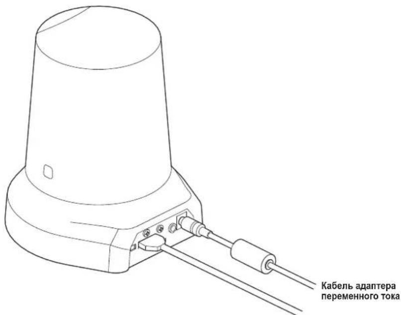
Ka6eBbXoHOrO BnDeocnHa
IcnoIb3yIe BINT IaY cTaNHOBKN WtATnBA, KOtOpBIO COOTBETCTBYET PnIBeDEHHOMY HNKe CTaHApTy.
Приимechания
He yctahabnbaTe yctpoiCTBO B MeCTax, Ie MIMO Hero NOCToHNO 6dyT XOINTb IIOIN.
- Ppi nCnOJIb3OBaHm yCTpoIcTBA, yCTaHOBJIeHHOro Ha IITATINB, He pa3MeIaIe TE IITATINB BbICOKo HAD yPOBHeM NOHa
- HadeKHO yCTaHOBITE yCTpoIcTBO, YTO6bI He 6bIIO paCsaTbIBAHnI. PaCsaTbIBAHme MOKe I npVBecTI K NaDEHIO yCTpoIcTBa N/INI TpaBMam.
- Ecni yctpoictBO 6ydtncnObl30BaTcB C TeueHne nnTeIbHOro nepnoa BpeMeHH, npmnte Mebp no npedotBpaueHIO OPOKnDIBaHn Hn nepeBopauHbAHn yctpoictBa, a TaKeNo npdeOTBpaueHIO ernoeHn. Nocne nCnObl30BaHn yctpoictBa He3ameNtEHLHO BOCCTAHOBNTe MecTo yCTAHOBKn Do nepBOHaayJIbHOcoCTOHN.
■ПоdkлоченkeКсистemeHDВИдевконферenu-СВЯЗИ
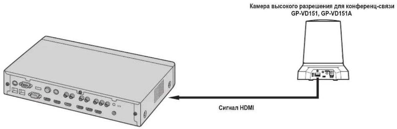
CnCTemaHD BIndeo KOhΦepeHu-CB3N
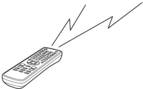
IynbT nctanHOnHO ynpaBneHn (DOnONHnTeNbHbN akceccyap)
AW-RM50G
- Ianyehn oncaHn onepaun noBopota, haknoHa, TpaHcfoKaun, BbIOJIeHn npEbnBbX yCTaHOBOK npynx onepaun kamepbI C nOMOuH cncTeMb HD BIneo KOHpepeHc-Bra3n 6oPbTecb K HcHcTpyKUn No 3KcNpyataun NpOdepKbMaEMrO yCtpoCTBa.
3Kcnnyatauia
| Симпом Пличina | И мерь lo устран�о | Стосясы Ддсрвок |
| ОсутствуETЗлкови элкови элкови элкови элкови элкови элкови элкови элкови элкови элкови элкови элкови элкови элкови элкови элкови элкови элкови элкови элкови ηзselfepeuHc-СВяз) | •Наджно Ли поклочen adanterep nepemeHHoro toka K pozetke nepemeHHoro toka? •Наджно Ли поклочen haTeencelbnaЯ bnilka adanterep na nepemeHHoro toka? •При улковелен ystpoiCTBOM c noMoOtsb noIylta dinSTahnOHHORO улковелен →Обатиесь takKE к рунКТу "He blyolnayOTcR opeaun C noMoOtsb noIylta dInstahnOHHORO uypablenya". | — |
| •Злковотане Вкluчedo: →Есни ИndikatOPнай лamma cosToHnRA ystpoiCTBa blykluoyeHa ил загораль opAnJxEBM ZBEtOM,ЗTO O3NaUaEТ,ЧТо ЗлковOTANe Ha ystpoiCTBa He noJaETcR. | <Опаци и установи> | |
| •Правильно Ли выбразуho улковамоу устpoiCTBO? | <Опаци и установи> | |
| He blyinHajotc олкови (обше дд пьытд дstahноHHORO улковелен, сsttemа HD БVDdeо кONDфepeHc-СВяз) | •Разядлесь Ли батейки пьытд nistahnOHoro улковелен ил pri уstahновке sbila nepenutana наюprnoctb sbatapeek? →Есни ИndikatOPнай лamma cosToHnRA He mIraet Дд配电 ecпоаци пьытм ДИstahnOHHORO улковелен blyinOLnKOTc B6IIm3 CBetoYbCTBHTbHoH oblaacti сгнala пьы dinStahnOHHORO улковелен, ЗTO O3NaUaEТ,ЧТо батейки разядлесь.ЗаменITE sbatapeяkn. | — |
| •ИмeeТСя Ли ВОЗе устpoiCTBA nICTOChNk ФлуоресentHORO оCbeSeHEN плплamazMeHHbI MOHITOP, И сдпд, He nonaAet Ли 3TO оCbeSeHEne Ha CBetoYbCTBHTbHуO oblaactb сгнala пьы dinStahnOHHORO улковелен? | стp.12 |
Bvdeo
Pexim3aHcBnamrB:0dB,6dB,12dB,18dB
Ckopoctb 3JneKToPOnHOro 3aTbopa:
Step: 1/100, 1/250, 1/500, 1/1000, 1/2000
1/4000, 1/10000
Synchro scan: Oτ 60,24 Hz do 646,21 Hz
Gamma: Off, Normal (Low, Mid, High), Cinema
Dnana3OH ypOBHeuCBeTHOCTN:
7 ypOBHeI ZBeTHoCTn
CIOXeTHbIe paJIbI: FullAuto, Manual1, Manual2, Manual3
BbIXoHoiΦopMaT:HD 1080:59,94p
HD 1080:59,94i
HD 1080:29,97p
HD 720:59,94p
SD 480:59,94p
[HaKIOHNO-NOBOPOTHOy yCTPOIcTBO]
Ckopoctb BblonHeHn opeauu noBopota/Haknoha:
Makc. 90^ s nii bojee
NC40 (pnpBbInONHeHHN
npedbapntelbHOy yctaHOBK)
AanTep nepemehHoro ToKa
[PGLV1009]
Bxod: O100Vdo240V nepemehHoroToKa,
1,2Ado0,6A,50Hz/60 Hz
BbIXoI: TocToHHoe HnnpJKeHne 12 V,2,O A
[PGLV1015]
Bxod: O100Vdo240V nepemehHoro Toka,
0,5Ado0,3A,50Hz/60Hz
BbIXoI: IocToHHoe HaprrKeHne 12 V,1,5 A
DOnonHnTeIbHbIe akceccyapbl
(Cyxa 6aTapeKa pa3Mepa "R6" nIN "LR6"×2, npno6petaTcra OTeJIbHo)
Yka3aHHbIe Bec n pa3MepbIy ABJIYIOCTc npi6m3nteJbHbIM.
TexHueckne xapaKTePcNTMn MOrT 6bITb N3MeHeHb 6e3 npedBapntelbHoro yBeDOMJIeHn.
DEUTSCHE AUSGABE
(GERMAN VERSION)
Sicherheitshinweise

VORSICHT
STROMSCHLAGGEFAHR NICTOTOFFNEN

VORSICHT: WEDER DECKEL NOCH RÜCKPLATTE
ABNEHMEN, UM DIE GEFAHR EINES
http://panasonic.net/psn/products/hdvc/resource/users_guide.shtml
14 Tasten OPT [ON] [OFF]
16 Tasten ZOOM [T] [W]
Gamma: Off, Normal (Low, Mid, High), Cinema
For Europe and other countries:
Panasonic Corporation
http://www.panasonic.com
Panasonic Corporation
Osaka, Japan
Authorised Representative in EU:
Panasonic Testing Centre
Panasonic Marketing Europe GmbH
Winsberging 15, 22525 Hamburg, Germany