
WVBM1910 - Surveillance Camera PANASONIC - Free user manual and instructions
Find the device manual for free WVBM1910 PANASONIC in PDF.
| Product Type | Video monitor for closed-circuit television (CCTV) system |
| Screen size (diagonal) | 473 mm (usable area), 505 mm (tube) |
| Horizontal resolution | 1,000 lines at center |
| Power supply | 220-240 V AC, 50 Hz |
| Power consumption | 47 W |
| Video input | Composite signal 1.0 Vp-p CCIR, 75 Ω, BNC connector |
| Video output | Loop-through via VIDEO IN connector, BNC |
| Connectors | BNC (input and output), power cord |
| Main controls | Brightness, contrast, horizontal/vertical hold, height, vertical linearity, scan width (normal/underscan), DC restoration |
| Operating temperature range | -10°C to +50°C |
| Maximum humidity | 90% |
| Supplied accessories | Power cord |
| Maintenance and cleaning | Use a dry cloth for cleaning; for stubborn stains, use a diluted neutral detergent. Do not use abrasive products. |
| Safety | Do not expose to rain or moisture. Do not open the device. Have all repairs carried out by qualified personnel. |
| Spare parts and repairability | No user-serviceable parts. Contact an authorized service center. |
Frequently Asked Questions - WVBM1910 PANASONIC
User questions about WVBM1910 PANASONIC
0 question about this device. Answer the ones you know or ask your own.
Ask a new question about this device
Download the instructions for your Surveillance Camera in PDF format for free! Find your manual WVBM1910 - PANASONIC and take your electronic device back in hand. On this page are published all the documents necessary for the use of your device. WVBM1910 by PANASONIC.
USER MANUAL WVBM1910 PANASONIC
Operating Instructions
Video Monitor
WV-BM1910
natural_image
Front view of a vintage CRT television set with control knobs and display screen (no visible text or labels)Panasonic
Before attempting to connect or operate this product, please read these instructions completely
ENGLISH VERSION
Vi erklærer os eneansvarlige for, at dette produkt, som denne deklaration omhandler, er i overensstemmelse med den følgende standarder eller andre normative dokumenter i følge bestemmelserne i direktivene 73/23/EEC og 89/336/EEC.
We declare under our sole responsibility that the product to which this declaration relates is in conformity with the standards or other normative documents following the provisions of Directives EEC/73/23 and EEC/89/336.
For Australia
THIS APPARATUS MUST BE EARTHED.
To ensure safe operation the three-pin plug supplied must be inserted only into a standard three-pin power point which is effectively earthed through the normal household wiring. Extension cords used with the equipment must be three-core and be correctly wired to provide connection to earth. Wrongly wired extension cords are a major cause of fatalities.
The fact that the equipment operates satisfactorily does not imply that the power point is earthed and that the installation is completely safe. For your safety, if in any doubt about the effective earthing of the power point, consult a qualified electrician.
CAUTION
RISK OF ELECTRIC SHOCK DO NOT OPEN

CAUTION:
TO REDUCE THE RISK OF ELECTRIC SHOCK, DO NOT REMOVE COVER (OR BACK). NO USER SERVICEABLE PARTS INSIDE.
REFER SERVICING TO QUALIFIED SERVICE PERSONNEL.
The lightning flash with arrowhead symbol, within an equilateral triangle, is intended to alert the user to the presence of uninsulated "dangerous voltage" within the product's enclosure that may be of sufficient magnitude to constitute a risk of electric shock to persons.

The exclamation point within an equilateral triangle is intended to alert the user to the presence of important operating and maintenance (servicing) instructions in the literature accompanying the appliance.
This appliance is supplied with a moulded three pin mains plug for your safety and convenience.
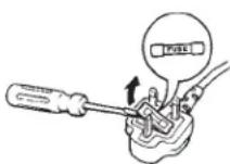
A 5 amp fuse is fitted in this plug.
Should the fuse need to be replaced please ensure that the replacement fuse has a rating of 5 amp and that it is approved by ASTA or BSI to BS1362.
Check for the ASTA mark 📂 or the BSI mark 🕒 on the body of the fuse.
If the plug contains a removable fuse cover you must ensure that it is refitted when the fuse is replaced.
If you lose the fuse cover the plug must not be used until a replacement cover is obtained.
A replacement fuse cover can be purchased from your local Panasonic Dealer.
IF THE FITTED MOULDED PLUG IS UNSUITABLE FOR THE SOCKET OUTLET IN YOUR HOME THEN THE FUSE SHOULD BE REMOVED AND THE PLUG CUT OFF AND DISPOSED OF SAFELY. THERE IS A DANGER OF SEVERE ELECTRICAL SHOCK IF THE CUT OFF PLUG IS INSERTED INTO ANY 5 AMP SOCKET.
If a new plug is to be fitted please observe the wiring code as shown below.
If in any doubt please consult a qualified electrician.
WARNING: This apparatus must be earthed.
IMPORTANT
The wires in this mains lead are coloured in accordance with the following code.
Green-and-yellow: Earth
Blue: Neutral
Brown: Live
As the colours of the wire in the mains lead of this appliance may not correspond with the coloured markings identifying the terminals in your plug, proceed as follows.
The wire which is coloured green-and-yellow must be connected to the terminal in the plug which is marked with the letter E or by the earth symbol ± or coloured green or green-and-yellow.
The wire which is coloured blue must be connected to the terminal in the plug which is marked with the letter N or coloured black.
The wire which is coloured brown must be connected to the terminal in the plug which is marked with the letter L or coloured red.
How to replace the fuse
Open the fuse compartment with
a screwdriver and replace the fuse and fuse cover.
The serial number of this product may be found on the rear of the unit.
You should note the serial number of this unit in the space provided and retain this book as a permanent record of your purchase to aid identification in the event of theft.
Model No. WV-BM1910
Serial No.
WARNING:
TO PREVENT FIRE OR ELECTRIC SHOCK HAZARD, DO NOT EXPOSE THIS APPLIANCE TO RAIN OR MOISTURE.
CONTENTS
PREFACE 1
FEATURES 1
PRECAUTIONS 1
MAJOR OPERATING CONTROLS AND THEIR FUNCTIONS 2
CONNECTIONS 4
SYSTEM CONNECTIONS 4
ADJUSTMENT 5
OPERATION 5
SPECIFICATIONS 6
STANDARD ACCESSORY 6
PREFACE
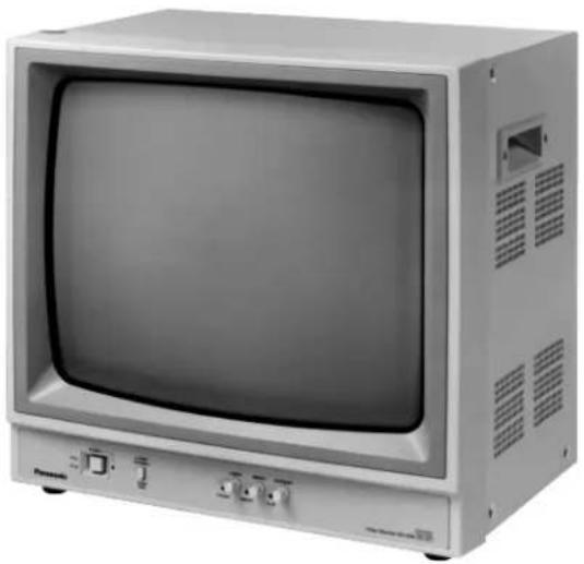
The Panasonic WV-BM1910 Video Monitor is a desk-top closed circuit Video Monitor especially designed for surveillance and studio applications.
This monitor features a 473 mm (18-5/8") actual diagonal viewing size screen and produces sharp,
black-and-white pictures with a horizontal resolution of 1 000 lines at centre.
The WV-BM1910 can be used with other CCTV monitors or Panasonic Video Tape Recorders.
FEATURES
- 473 mm (18-5/8") actual diagonal viewing size.
- Horizontal resolution is 1 000 lines at centre of screen.
- Under or normal scan size (switchable).
PRECAUTIONS
- Refer all work related to the installation of this product to qualified service personnel or system installers.
- Do not block the ventilation opening or slots on the cover.
To prevent the appliance from overheating, place the monitor at least 5 cm (2 inches) away from the wall.
- Do not drop metallic parts through slots.
This could permanently damage the appliance. Turn the power off immediately and contact qualified service personnel for service.
- Do not attempt to disassemble the appliance.
To prevent electric shock, do not remove screws or covers.
There are no user-serviceable parts inside. Contact qualified service personnel for maintenance.
- Handle the appliance with care.
Do not strike or shake, as this may damage the appliance.
- Do not expose the appliance to water or moisture, nor try to operate it in wet areas.
Do take immediate action if the appliance becomes wet. Turn the power off and refer servicing to qualified service personnel. Moisture may damage the appliance and also cause electric shock.
- Do not use strong or abrasive detergents when cleaning the appliance body.
Use a dry cloth to clean the appliance when it is dirty.
When the dirt is hard to remove, use a mild detergent and wipe gently.
- Do not operate the appliance beyond its specified temperature, humidity or power source ratings.
Use the appliance at temperatures within -10^ to +50^ ( 14^ to 122^ ) and a humidity below 90 %.
The input power source for this appliance is 220 - 240 V AC 50 Hz.
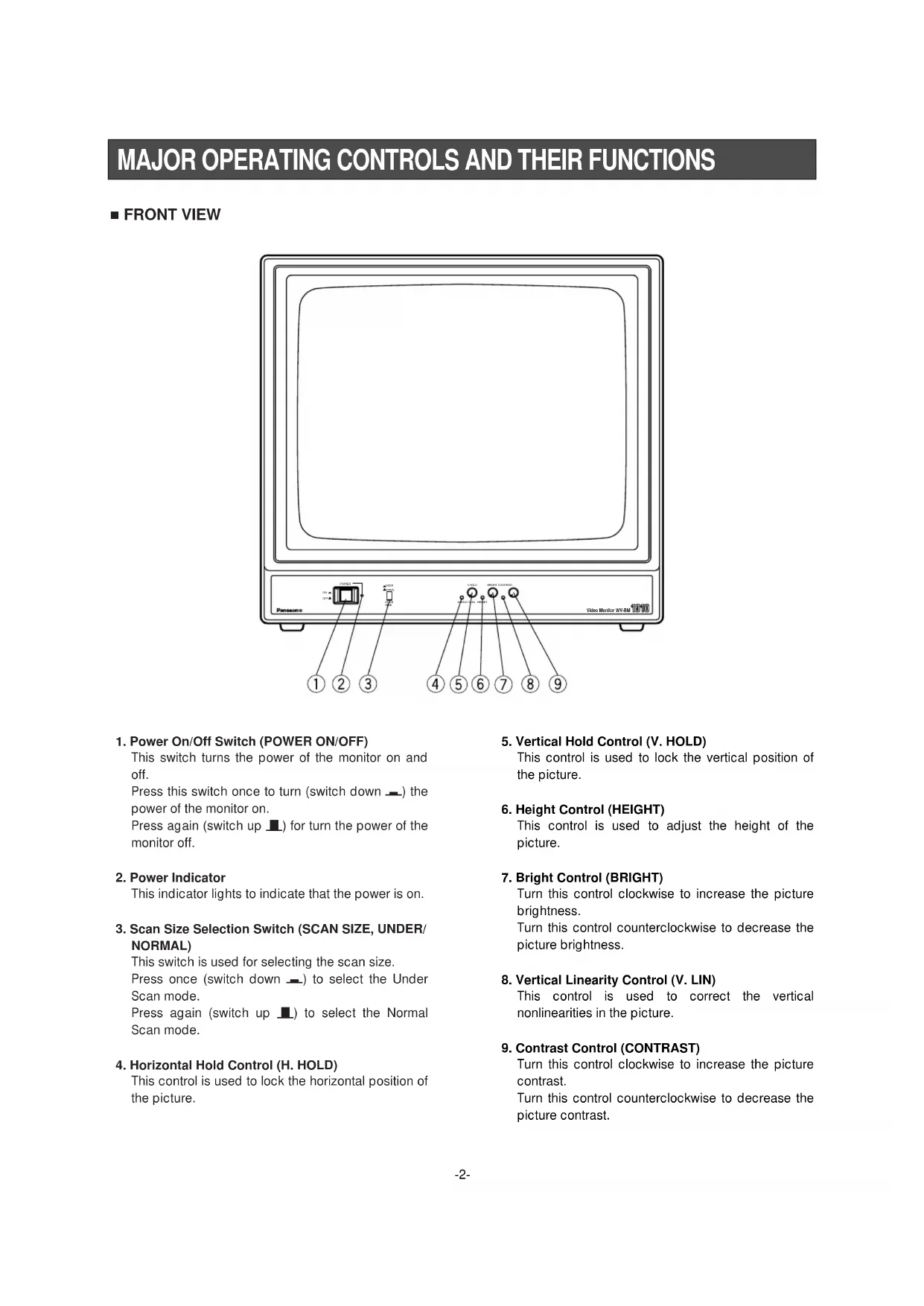
MAJOR OPERATING CONTROLS AND THEIR FUNCTIONS
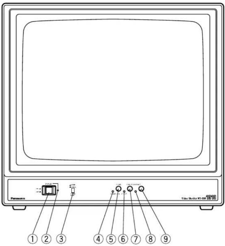
■ FRONT VIEW
text_image
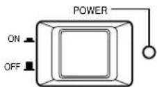
Panasonic Vide Monitor W7-BM 1910 ① ② ③ ④ ⑤ ⑥ ⑦ ⑧ ⑨1. Power On/Off Switch (POWER ON/OFF)
This switch turns the power of the monitor on and off.
Press this switch once to turn (switch down_) the power of the monitor on.
Press again (switch up ▲) for turn the power of the monitor off.
2. Power Indicator
This indicator lights to indicate that the power is on.
3. Scan Size Selection Switch (SCAN SIZE, UNDER/NORMAL)
This switch is used for selecting the scan size.
Press once (switch down —) to select the Under Scan mode.
Press again (switch up ▪) to select the Normal Scan mode.
4. Horizontal Hold Control (H. HOLD)
This control is used to lock the horizontal position of the picture.
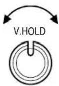
5. Vertical Hold Control (V. HOLD)
This control is used to lock the vertical position of the picture.
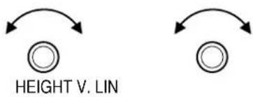
6. Height Control (HEIGHT)
This control is used to adjust the height of the picture.
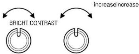
7. Bright Control (BRIGHT)
Turn this control clockwise to increase the picture brightness.
Turn this control counterclockwise to decrease the picture brightness.
8. Vertical Linearity Control (V. LIN)
This control is used to correct the vertical nonlinearities in the picture.
9. Contrast Control (CONTRAST)
Turn this control clockwise to increase the picture contrast.
Turn this control counterclockwise to decrease the picture contrast.
■ REAR VIEW
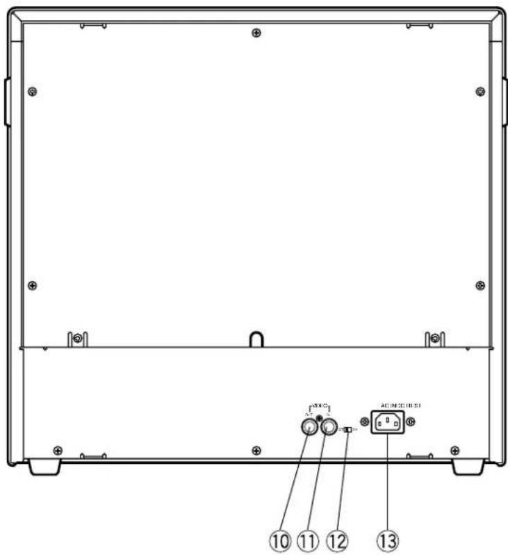
text_image
⑩ ⑪ ⑫ ⑬ ⑬ ⑭ ⑮ ⑯ ⑰ ⑱ ⑲10. Video Output Connector (VIDEO OUT)
This BNC type connector is used to provide the video output signal of the source to an additional monitor or video tape recorder.
11. Video Input Connector (VIDEO IN)
This BNC type connector is used for receiving the video signal from a source to be monitored, such as a VTR.
12. DC Restoration Switch (DC REST ON/OFF)
Select ON or OFF to restore background of picture or not.
13. AC IN
CONNECTIONS
Power Cord
- Keep the Power ON/OFF switch of the camera in the OFF position during installation.
- Connect the Power Cord to a grounded electrical outlet.
Video Cable
Use a 75 Ω coaxial cable (RG-59, RG-59A/U, RG-59B/U, RG-59/U, RG-6/U, or RG-11/U).
-
Up to 10 monitors can be hooked up in this configuration before signal loss occurs. Total cable length should not be longer than 150 meters (500 feet).
-
Wiring Precautions :
Do not bend the coaxial cable into a curve whose radius is smaller than 10 times its diameter. Never staple coaxial cables, not even with circular staples.
Never crush or pinch the cable.
All of the above will change the impedance of the cable and cause poor picture quality.
SYSTEM CONNECTIONS
1. Single Monitor Connection
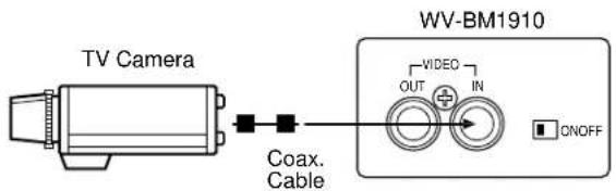
text_image
TV Camera Coax. Cable WV-BM1910 VIDEO OUT IN ONOFF- Connect the Video Input Connector (VIDEO IN) on this monitor to the Video Output Connector of the video source with a coaxial cable.
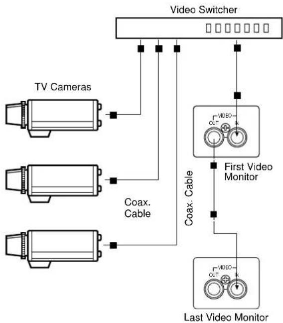
2. Multiple Monitor Connection
flowchart
graph TD
    A["TV Cameras"] --> B["Coax. Cable"]
    C["TV Cameras"] --> D["Coax. Cable"]
    E["TV Cameras"] --> F["Coax. Cable"]
    G["TV Cameras"] --> H["Coax. Cable"]
    I["Video Switcher"] --> J["First Video Monitor"]
    K["Video Switcher"] --> L["Coax. Cable"]
    M["Video Switcher"] --> N["Coax. Cable"]
    O["Video Switcher"] --> P["Coax. Cable"]
    Q["Video Switcher"] --> R["Coax. Cable"]
    S["Video Switcher"] --> T["Coax. Cable"]
    U["Video Switcher"] --> V["Coax. Cable"]
    W["Video Switcher"] --> X["Coax. Cable"]
    Y["Video Switcher"] --> Z["Coax. Cable"]
    AA["Video Switcher"] --> AB["Coax. Cable"]
    AC["Video Switcher"] --> AD["Coax. Cable"]
    AE["Video Switcher"] --> AF["Coax. Cable"]
    AG["Video Switcher"] --> AH["Coax. Cable"]
    AI["Video Switcher"] --> AJ["Coax. Cable"]
    AK["Video Switcher"] --> AL["Coax. Cable"]
    AM["Video Switcher"] --> AN["Coax. Cable"]
    AO["Video Switcher"] --> AP["Coax. Cable"]
    AQ["Video Switcher"] --> AR["Coax. Cable"]
    AS["Video Switcher"] --> AT["Coax. Cable"]
    AU["Video Switcher"] --> AV["Coax. Cable"]
    AW["Video Switcher"] --> AX["Coax. Cable"]
    AY["Video Switcher"] --> AZ["Coax. Cable"]
    BA["Video Switcher"] --> BB["Coax. Cable"]
    BC["Video Switcher"] --> BD["Coax. Cable"]
    BE["Video Switcher"] --> BF["Coax. Cable"]
    BG["Video Switcher"] --> BH["Coax. Cable"]
    BI["Video Switcher"] --> BJ["Coax. Cable"]
    BK["Video Switcher"] --> BL["Coax. Cable"]
    BM["Video Switcher"] --> BN["Coax. Cable"]
    BO["Video Switcher"] --> BP["Coax. Cable"]
    BP --> BQ["Video Switcher"]
- Connect the Video Input Connector (VIDEO IN) on this monitor to the Video Output Connector of the video source with a coaxial cable.
- Connect the Video Output Connector (VIDEO OUT) on this monitor to the Video Input Connector (VIDEO IN) on the second monitor with a coaxial cable.
- Complete the connections of all monitors in the system according to the above procedure.
ADJUSTMENT
Preparations:
Make sure that all required connections in the system are completed.
Turn on the power of this monitor by pressing the Power On/Off Switch on the front panel.
- Adjust the brightness by the Bright Control (BRIGHT) and the Contrast Control (CONTRAST) so that the overall brightness is appropriate and grey tones are resolved.
flowchart
graph TD
    A["BRIGHT CONTRAST"] --> B["increase"]
    B --> C["increase"]
- If the picture slips to either side, or a series of horizontal lines appear, adjust the Horizontal Hold Control (H.HOLD) until the picture is stabilized.

- If the picture rolls up or down, adjust the Vertical Hold Control (V.HOLD) until the picture is stabilized.
- The sub controls, HEIGHT and V. LINEARITY, should be adjusted at the same time to give proper vertical height consistent with good vertical linearity. Extending the picture height approximately 6 mm (1/4") beyond the top and bottom edges of the CRT mask is recommended.
Press the Scan Size Selection Switch (SCAN SIZE) once (switch down_) to set the UNDER position.
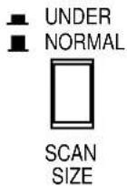
Press again (switch up ▲) to NORMAL position.
DC Restoration
DC restoration circuit provides a stable reference for the black level.
Set the switch to ON to prevent excessive contrast and preserve shadow detail.

SPECIFICATIONS
Power Source : 220 - 240 V AC, 50 Hz
Power Consumption : Approx. 47 W
Video Input : 1.0 V[p-p] CCIR composite/75 Ω x 1
Video Output: Looping through VIDEO IN connector x 1
Horizontal Resolution : 1 000 TV lines at centre
Sweep Linearity : Less than 5 % at overscan
Sweep Geometry : Less than 2 % at overscan
Overscanning : Approx. 6 %
Scanning Size : Normal or underscan, selectable
Tube Size : 473 mm (18-5/8") diagonal actual visual size
505 mm (19-7/8") diagonal tube screen size
Ambient Operating Temperature : -10^ - +50^ ( 14^ - 122^ )
Ambient Operating Humidity : Less than 90 %
Dimensions : 483(W) X 443(H) X 329(D) mm
Weight and dimensions shown are approximate.
Specifications are subject to change without notice.
STANDARD ACCESSORY
Power Cord 1 pc.
DEUTSCHE AUSGABE
(GERMAN VERSION)
INHALT
text_image
⑩ ⑪ ⑫ ⑬ ⑬ ⑭ ⑮ ⑯ ⑰ ⑱ ⑲Dimensions: 483 (L) x 443 (H) x 329 (P) mm
Poids: 20 kg
text_image
⑩ ⑪ ⑫ ⑬ ⑬ ⑭ ⑮ ⑯ ⑰ ⑱ ⑲Matsushita Electric Industrial Co., Ltd.
Central P.O. Box 288, Osaka 530-91, Japan
N1098-0 YWV8QA5040AN Printed in Japan
