WVBP130 - Surveillance Camera PANASONIC - Free user manual and instructions
Find the device manual for free WVBP130 PANASONIC in PDF.
User questions about WVBP130 PANASONIC
0 question about this device. Answer the ones you know or ask your own.
Ask a new question about this device
Download the instructions for your Surveillance Camera in PDF format for free! Find your manual WVBP130 - PANASONIC and take your electronic device back in hand. On this page are published all the documents necessary for the use of your device. WVBP130 by PANASONIC.
USER MANUAL WVBP130 PANASONIC
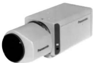
CCTV Cameras WV-BP130/WV-BP132/WV-BP134
BOHSITONE
TON
ESIVONAN

Operating Instructions
(Lens : option)
Panasonic
Before attempting to connect or operate this product, please read these instructions completely.
ENGLISH VERSION
The lightning flash with arrowhead symbol, within an equilateral triangle, is interned to alert the user to the presence of uninsulated "dangerous voltage" within the product's enclosure that may be of sufficient magnitude to constitute a risk of electric shock to persons.

The exclamation point within an equilateral triangle is intended to alert the user to the presence of important operating and maintenance (servicing) instructions in the literature accompanying the appliance.
We declare under our sole responsibility that the product to which this declaration relates is in conformity with the standards or other normative documents following the provisions of Directives EEC/73/23 and EEC/89/336.
TO PREVENT FIRE OR ELECTRIC SHOCK HAZARD, DO NOT EXPOSE THIS APPLIANCE TO RAIN OR MOISTURE.
FOR YOUR SAFETY PLEASE READ THE FOLLOWING TEXT CAREFULLY.
This appliance is supplied with a moulded three pin mains plug for your safety and convenience.
A 5 amp fuse is fitted in this plug.
Should the fuse need to be replaced please ensure that the replacement fuse has no settings of (see and that it is mounted by ASTA or BSI in
RS1362
Check for the ASTA mark or the BSI mark on the body of the fuse If the plug contains a removable fuse cover you must ensure that it is refit- ted when the fuse is replaced.
If you lose the fuse cover the plug must not be used until a replacement cover is obtained.
A replacement fuse cover can be purchased from your local Panasonic
Dealer.
IF THE FITTED MOULDED PLUG IS UNSUITABLE FOR THE SOCKET OUTLET IN YOUR HOME THEN THE FUSE SHOULD BE REMOVED AND THE PLUG CUT OFF AND DISPOSED OF SAFELY. IF THE FUSE IS GENDERED OFF, THE FUSE WILL BE SHOCK IF THE CUT OFF PLUG IS INSERTED INTO ANY 13 AMP SOCKET.
If a new plug is to be fitted please observe the wiring code as shown below.
If in any doubt please consult a qualified electrician.
WARNING: This apparatus must be earthed.
IMPORTANT
The wires in this mains lead are coloured in accordance with the following code.
Green-and-yellow: Earth
Blue: Neutral
Brown: Live
As the colours of the wire in the mains lead of this appliance may not correspond with the coloured markings identifying the terminals in your plug, proceed as follows.
The wire which is coloured green-and-yellow must be connected to the terminal in the plug which is marked with the letter E or by the earth symbol ± or coloured green or green-and-yellow.
The wire which is coloured blue must be connected to the terminal in the plug which is marked with the letter N or coloured black.
The wire which is coloured brown must be connected to the terminal in the plug which is marked with the letter L or coloured red.
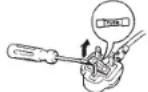
How to replace the fuse
Open the fuse compartment with a screwdriver and replace the fuse and fuse cover.
The serial number of this product may be found on the top of the unit.
You should note the serial number of this unit in the space provided and retain this book as a permanent record of your purchase to aid identification in the event of theft.
Model No.
Serial No.
CONTENTS
PREFACE 3
FEATURES 3
PRECAUTIONS 4
MAJOR OPERATING CONTROLS AND THEIR FUNCTIONS 5
CONNECTIONS 8
FOCUS OR BACK-FOCAL ADJUSTMENT 13
INSTALLATION OF CAMERA 14
PREVENTION OF BLOOMING AND SMEAR 15
SPECIFICATIONS 16
STANDARD ACCESSORIES 17
PREFACE
Panasonic's WV-BP130 series introduces a new level of high picture quality and high resolution through the use of a 1/3-inch interline transfer CCD image sensor having 512 horizontal pixels (picture elements). This
model offers cutting-edge technology for advanced video surveillance.
FEATURES
- The following functions are built-in.
(1) Auto Light Control (ALC)/Electronic Light Control (ELC)
(2) Back Light Compensation
(3) Line-locked Sync or automatic switching Multiplexed Vertical Drive (VD2) (only WV-BP130 and WV-BP134)/Internal Sync or automatic switching VD2 (only WV-BP132) - Signal-to noise ratio of 46 dB
- Minimum illumination of 0.08 lx (0.008 foot-candle) with F1.4 lenses
-
Horizontal resolution of 380 lines
-
Shooting of indoor scenes with fixed iris lens by use of Electronic Light Control (ELC) function
- Selectable auto iris control signal for the lens from a video signal or DC control signal
PRECAUTIONS
- Do not attempt to disassemble the camera.
To prevent electric shock, do not remove screws or covers.
There are no user serviceable parts inside. Ask a qualified service person for servicing.
- Handle the camera with care.
Do not abuse the camera. Avoid striking, shaking, etc. The camera could be damaged by improper handling or storage.
- Do not expose the camera to rain or moisture, or try to operate it in wet areas.
Turn the power off immediately and ask a qualified service person for servicing. Moisture can damage the camera and also create the danger of electric shock.
- Do not use strong or abrasive detergents when cleaning the camera body.
Use a dry cloth to clean the camera when dirty. In case the dirt is hard to remove, use a mild detergent and wipe gently.
- Clean the CCD faceplate with care.
Do not clean the CCD with strong or abrasive detergents. Use lens tissue or a cotton tipped applicator and ethanol.
- Never face the camera towards the sun.
Do not aim the camera at bright objects. Whether the camera is in use or not, never aim it at the sun or other extremely bright objects. Otherwise, blooming or smear may be caused.
- Do not operate the camera beyond the specified temperature, humidity or power source ratings.
Use the camera under conditions where temperature is between -10^ + 50^ 14^ - 122^, and humidity is below 90% . The input power source is 220-240V AC, 50Hz for WV-BL130, AC 24V 50 Hz for WV-BP134, 12V DC for WV-BL132.
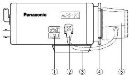
MAJOR OPERATING CONTROLS AND THEIR FUNCTIONS
WV-BP130 WV-BP132 WV-BP134
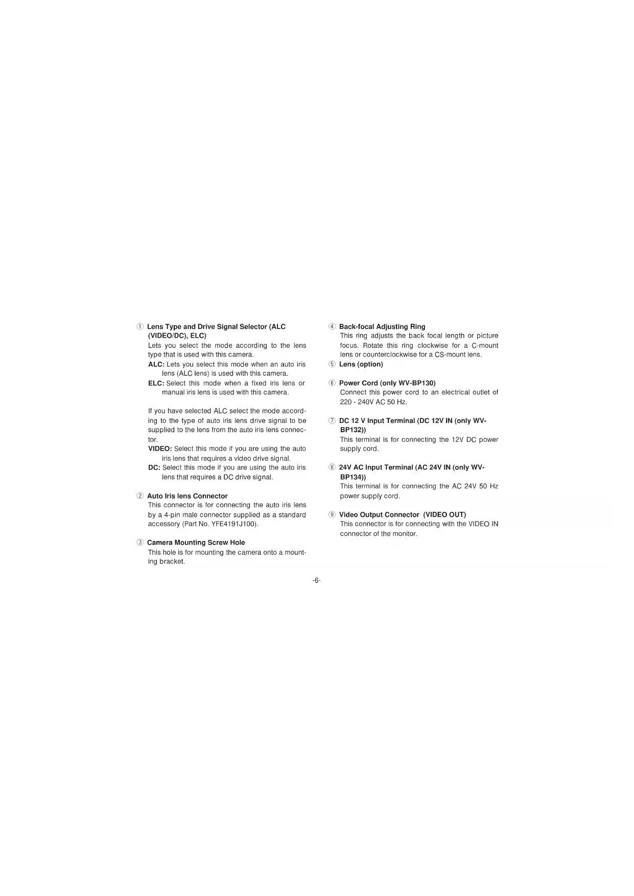
Lens Type and Drive Signal Selector (ALC (VIDEO/DC), ELC)
Lets you select the mode according to the lens type that is used with this camera.
ALC: Lets you select this mode when an auto iris lens (ALC lens) is used with this camera.
ELC: Select this mode when a fixed iris lens or manual iris lens is used with this camera.
If you have selected ALC select the mode according to the type of auto iris lens drive signal to be supplied to the lens from the auto iris lens connector.
VIDEO: Select this mode if you are using the auto iris lens that requires a video drive signal.
DC: Select this mode if you are using the auto iris lens that requires a DC drive signal.
2 Auto Iris lens Connector
This connector is for connecting the auto iris lens by a 4-pin male connector supplied as a standard accessory (Part No. YFE4191J100).
③ Camera Mounting Screw Hole
This hole is for mounting the camera onto a mounting bracket.
4 Back-focal Adjusting Ring
This ring adjusts the back focal length or picture focus. Rotate this ring clockwise for a C-mount lens or counterclockwise for a CS-mount lens.
⑤ Lens (option)
6 Power Cord (only WV-BP130)
Connect this power cord to an electrical outlet of 220 - 240V AC 50 Hz.
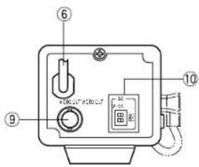
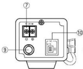
DC 12 V Input Terminal (DC 12V IN (only WVBP132))
This terminal is for connecting the 12V DC power supply cord.
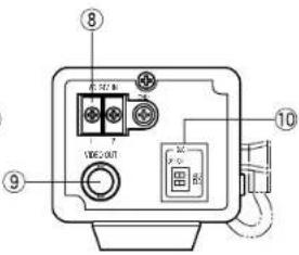
24V AC Input Terminal (AC 24V IN (only WVBP134))
This terminal is for connecting the AC 24V 50 Hz power supply cord.
⑨ Video Output Connector (VIDEO OUT)
This connector is for connecting with the VIDEO IN connector of the monitor.
Back Light Compensation On/Off Selectors (BLC ON/OFF, ALC/ELC)
Lets you select BLC ON or OFF according to the position of the object and light condition in the screen.
BLC ON: Select this mode if the background light is strong such as a spotlight. The back light compensation functions.
OFF: Normal camera picture is displayed.
- Confirm the position of the lens type and drive signal selector.
- If you have selected ALC (VIDEO/DC), use the upper selector (ALC) to select the mode. If ELC is selected, select the mode by lower selector (ELC).
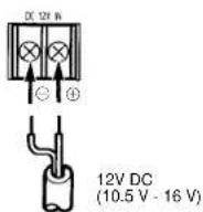
Caution:
Connect to 12V DC (10.5V-16V) or 24V AC (19.5V-28V) class 2 power supply only. Make sure to connect the grounding lead to the GND terminal when the power is supplied from a 24V AC power source.
CONNECTIONS
A.WV-BP130 (220-240V AC 50 Hz)
Connect the power cord to an electrical outlet of 220 - 240V AC 50 Hz.
B.WV-BP132 (12V DC)
Connect the power cord to the DC 12V IN terminal on the rear panel of the WV-BP132.
Resistance of copper wire [at 20^ (68^)]
| Copper wire #24 #22 #20 #18 size (AWG) (0.22mm) | (0.33mm) | (0.52mm) | (0.83mm) | |
| Resistance 0.078 Ω/m | 0.050 | 0.030 | 0.018 | |
| Resistance 0.026 Ω/II | 0.017 | 0.010 | 0.006 | |
Calculation of maximum cable length between camera and power supply :
$$ 1 0. 5 V D C \leq V _ {A} - (R \times 0. 4 2 \times L) \leq 1 6 V D C $$
L: Cable length (meters)
R: Resistance of copper wire (/meters)
V_ : DC output voltage of power supply unit
$$ L \text {s t a n d a r d} = \frac {V _ {h} - 1 2}{\text {(m o l e r s)}} $$
$$ L \text {m i n i m u m} = \frac {V _ {A} - 1 6}{\text {(m e t e r s)}} $$
$$ L \text {m a x i m u m} = \frac {V _ {A} - 1 0 . 5}{\text {(m e t e r s)}} $$
C.WV-BP134 (24V AC 50 Hz)
Connect the power cable to the AC 24V IN terminal on the rear panel of the WV-BP134.
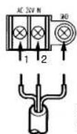
24V AC, 50 Hz (19.5 V - 28 V)
Recommended wire gauge sizes for 24V AC line
| Copper wire #24 #22 #20 #18 size (AWG) (0.22mm -) | 0.33mm +) | 0.52mm +) | 0.83mm +) | |
| Length (m) of Cable (Approx.) (h) | 95 150 255 425 | |||
| 314 495 842 1 403 | ||||
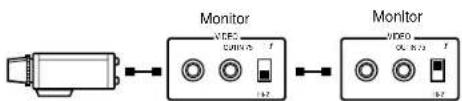
Video Cable
- It is recommended to use a monitor whose resolution is at least equal to that of the camera.
- Set the termination switch to the 75Ω position on the last monitor.
A.Use a 75Ω coaxial cable.
B. Set the termination switch to the 75Ω position on the last monitor and to the Hi-Z position on the other monitors. Do not change the positions after setting.
C. The maximum extensible coaxial cable length between the camera and the monitor is shown below.
| Type of RG-59/U RG-6/U RG-11/U RG-15/U coaxial cable (3C-2V) (SC-2V) (7C-2V) (10C-2V) | |||
| Recommended (m) maximum cable length (ft) | 250 | 500 600 800 | |
| 25 | 1 660 1 980 2 640 | ||
3. Wiring precautions
- Do not bend the coaxial cable into a curve whose radius is smaller than 10 times the cable's diameter.
- Never staple the cable, not even with circular staples. Impedance mismatching will occur.
- Never crush or pinch the cable.
All of the above will change the impedance of the cable and cause poor picture quality.
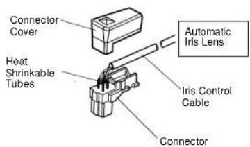
Installation of Auto Iris Lens Connector
Install the lens connector (YFE4191J100) when using a video drive ALC lens.
The installation should be made by qualified service personnel or system installers.
(1) Cut the iris control cable at the edge of the lens connector to remove the existing lens connector and then remove the outer cable cover as shown in the diagram below.
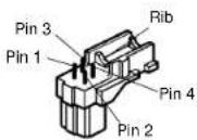
The pin assignment of the lens connector is as follows:
Pin 1: Power source; +9V DC, 50mA max.
Pin 2: Not used
Pin 3: Video signal; 0.7 V[p-p]/40 kΩ
Pin 4:Shield, ground
(2) After connection, assemble the lens connector as follows.
Note: When the iris control cable is too thick to lock the connector cover with the connector base, cut off the rib on the connector.
(Set the lens type and drive signal selector to VIDEO)
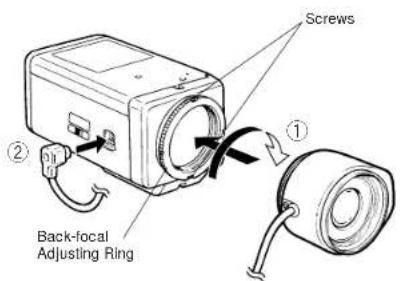
Mounting the Lens
Caution:
Before you mount the lens, loosen the two screws on the ring, and rotate this ring clockwise until it stops. If the ring is not at the end, the inner Lens or CCD image sensor may be damaged.
- Mount the lens by turning it clockwise on the lens mount of the camera.
- Connect the lens cable to the auto iris lens connector on the side of the camera.
Caution for Mounting the Lens
The lens mount should be a C-mount or CS-mount (1"32UN) and the lens weight should be less than 450g (0.99 lbs). If the lens is heavier, both the lens and camera should be secured by using the supporter.
The protrusion at the rear of the lens should be as shown below:

FOCUS OR BACK-FOCAL ADJUSTMENT
The following adjustment should be made by qualified service personnel or system installers.
- Loosen the screws on the back-focal adjusting ring.
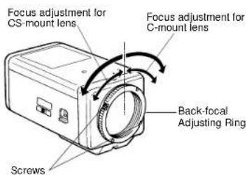
- Turn the back-focal adjusting ring to the desired position.
Caution: When the C-mount lens is mounted, do not rotate the ring counterclockwise by force after it stops. If the ring is rotated by force, the inner lens or CCD image sensor may be damaged.
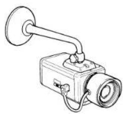
INSTALLATION OF CAMERA
- Mounting from the bottom
This camera is designed to be mounted from the bottom, as shown below. The mounting hole is a standard photographic pan-head screw size (1/4" - 20).
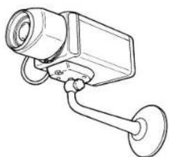
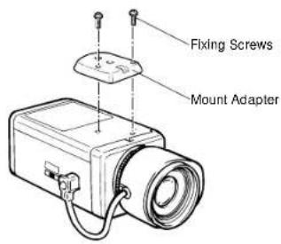
- Mounting from the top
Remove the mount adapter from the bottom of the camera by removing the two fixing screws. Attach the mount adapter to the top as shown in the diagram, then mount the camera on the mounting bracket.
Make sure that the two original fixing screws are used when mounting the mount adapter as longer length screws may damage inner components.
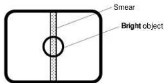
PREVENTION OF BLOOMING AND SMEAR
When the camera is aimed at a bright light, such as a spotlight, or a surface that reflects bright light, smear or blooming may appear. Therefore, the camera should be operated carefully in the vicinity of extremely bright objects to avoid smear or blooming.
SPECIFICATIONS
Pick-up Device: 512 (H) x 582 (V) pixels, Interline Transfer CCD
Scanning Area: 4.8 (H) x 3.6 (V) mm (Equivalent to scanning area of 1/3 pick-up tube)
Synchronization: Line-locked or Multiplexed Vertical Drive (VD2) for WV-BP130 and WV-BP134
Internal or Multiplexed Vertical Drive (VD2) for WV-BP132
Scanning System: 2 : 1 interlace
Scanning: 625 lines / 50 fields / 25 frames
Horizontal: 15.625 kHz
Vertical: 50 Hz
Video Output: 1.0 V[p-p] CCIR composite 75 Ω / BNC connector
Horizontal Resolution: 380 lines
Signal-to-Noise Ratio: 46 dB
Electronic Light Control: Equivalent to continuous variable shutter speed between 1/50 s
and 1/80 000 s
Minimum Illumination: 0.08 lx (0.008 foot-candle) at F1.4
Lens Mount: C-mount or CS-mount selectable
Ambient Operating Temperature: -10^ + 50^ (14°F - 122°F)
Ambient Operating Humidity: Less than 90%
Power Source and WV-BP130 220 - 240V AC 50 Hz, 3.0W
Power Consumption: WV-BP132 12V DC 160 mA
WV-BP134 24V AC 50Hz, 2.8W
Dimensions (without lens): 67 (W) x 55 (H) x 123 (D) mm
[2-5/8" (W) x 2-3/16" (H) x 4-13/16" (D)]
Weights (without lens): WV-BP130 630 g (1.39 lbs.)
WV-BP132 410 g (0.90 lbs.)
WV-BP134 440 g (0.97 lbs.)
Weights and dimensions indicated are approximate.
Specifications are subject to change without notice.
STANDARD ACCESSORIES
Body Cap 1 pc.
ALC Lens Connector (YFE4191J100) 1 pc.
DEUTSCHE AUSGABE
(GERMAN VERSION)

CAUTION
BISK OF ELECTRIC SHOCK
DO NOT OPEN

WARNING:
WEDER DECKEL NOCH RUCKPLATTE
ABNEHMEN. UM DIE GEFAHR EINES ELEK
Horizontal: 15.625 kHz
Vertikal: 50,00Hz
ACCESSIONS STANDARD 51
PREFACE
Recommended wire gauge sizes for 24V AC line
| Tamanho de cable #24 #22 #20 de cobra (AWG) (0.22mm - ) | 18 (0.33mm - ) | (0.52mm - ) | (0.83mm - ) | |
| Longitud del cable (m) (aprox.) | 95 150 | 255 425 | ||
Cable de video
Montura C:Loses of 1.5 mm Montura CS:Loses of 7,2mm
Horizontal: 15.625 kHz
Vertical: 50.00Hz
WV-BP132410g WV-BP134440g
Matsushita Electric Industrial Co., Ltd.
Central P.O.Box 288, Osaka 530-91, Japan
N0398-0 YWV8QA4931AN Printed in Japan