
WVBP50 - Surveillance Camera PANASONIC - Free user manual and instructions
Find the device manual for free WVBP50 PANASONIC in PDF.
| Product Type | Surveillance Camera |
| Horizontal Resolution | 380 lines |
| Minimum Illumination | 0.08 lx at F1.4 |
| Signal-to-Noise Ratio | 50 dB (AGC off, weighting applied) |
| Electronic Light Control | Equivalent to continuous variable shutter speed from 1/50 s to 1/80,000 s |
| Lens Mount | CS Mount |
| Operating Temperature | -10 °C to +50 °C |
| Maximum Humidity | 90% |
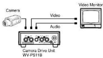
| Power Supply | Provided by WV-PS11B or WV-PS104C (not included) |
| Synchronization | Multiplexed frame control signal (VD2) via specified control unit |
| Video Output | Composite video signal 1.15 V[p-p], 75 Ω |
| Image Sensor | Interline transfer charge-coupled device 512 (H) x 582 (V) pixels |
| Scanning Area | 4.8 (H) x 3.6 (V) mm |
| Scanning System | 2:1 interlace, 625 lines / 50 fields / 25 frames |
| Supplied Accessories | Lens cap, Mounting bracket |
| Optional Accessories | C/CS mount lenses, control unit WV-PS11B, mount adapter WV-AD20 |
| Maintenance and Cleaning | Clean the cabinet with a dry cloth. For the DTC device, use special lens cleaning sheets or a cotton swab moistened with ethanol. Do not use abrasive detergents. |
| Safety | Do not disassemble. Avoid exposure to rain or moisture. Do not point at the sun. Have all repairs performed by a qualified professional. |
Frequently Asked Questions - WVBP50 PANASONIC
User questions about WVBP50 PANASONIC
0 question about this device. Answer the ones you know or ask your own.
Ask a new question about this device
Download the instructions for your Surveillance Camera in PDF format for free! Find your manual WVBP50 - PANASONIC and take your electronic device back in hand. On this page are published all the documents necessary for the use of your device. WVBP50 by PANASONIC.
USER MANUAL WVBP50 PANASONIC
Operating Instructions
Before attempting to connect or operate this product, please read these instructions carefully.
N0499-0 YWV8QA5178AN Printed in Japan
30

The lightning flash with arrowhead symbol, within an equilateral triangle, is intended to alert the user to the presence of uninsulated "dangerous voltage" within the product's enclosure that may be of sufficient magnitude to constitute a risk of electric shock to persons.

The exclamation point within an equilateral triangle is intended to alert the user to the presence of important operating and maintenance (servicing) instructions in the literature accompanying the appliance.
We declare under our sole responsibility that the product to which this declaration relates is in conformity with the standards or other normative documents following the provisions of Directive EEC/89/336.
The serial number of this product may be found on the top of the unit.
You should note the serial number of this unit in the space provided and retain this instruction as a permanent record of your purchase to aid identification in the event of theft.
Model No.
Serial No.
WARNING:
TO PREVENT FIRE OR ELECTRIC SHOCK HAZARD, DO NOT EXPOSE THIS APPLIANCE TO RAIN OR MOISTURE.
FEATURES
- Auto Light Control (ALC)/Electronic Light Control (ELC)
Automatic Gain Control (AGC) +18 dB
Minimum illumination of 0.08lx (0.008 foot candle) at F1.4
Signal-to-noise ratio of 46 dB
Horizontal resolution of 380 lines
- Easy connection with specified monitor by a coaxial cable
PRECAUTIONS
- Do not attempt to disassemble the camera. To prevent electric shock, do not remove screws or covers. There are no user serviceable parts inside. Ask a qualified service person for servicing.
- Handle the camera with care. Do not abuse the camera. Avoid striking, shaking, etc. The camera could be damaged by improper handling or storage.
- Do not expose the camera to rain or moisture, or try to operate it in wet areas. Turn the power off immediately and ask a qualified service person for servicing. Moisture can damage the camera and also create the danger of electric shock.
-
Do not use strong or abrasive detergents when cleaning the camera body. Use a dry cloth to clean the camera when dirty. In case the dirt is hard to remove, use a mild detergent and wipe gently.
-
Clean the CCD faceplate with care. Do not clean the CCD with strong or abrasive detergents. Use lens tissue or a cotton tipped applicator and ethanol.
-
Never face the camera towards the sun. Do not aim the camera at bright objects. Whether the camera is in use or not, never aim it at the sun or other extremely bright objects. Otherwise, blooming or smear may be caused.
-
Do not operate the camera beyond the specified temperature, humidity or power source ratings.
Use the camera under conditions where temperature is between -10^ + 50^ 14^- 122^) , and humidity is below 90%
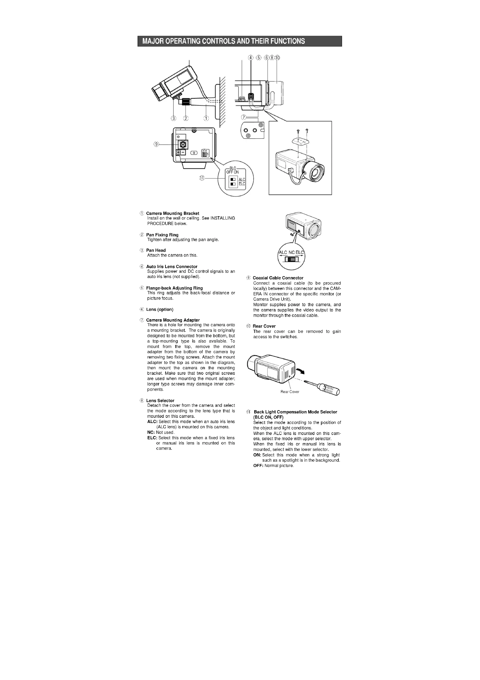
MAJOR OPERATING CONTROLS AND THEIR FUNCTIONS
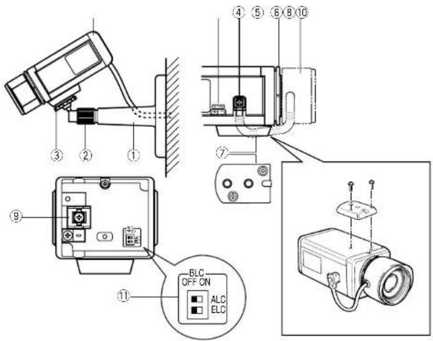
① Camera Mounting Bracket
Install on the wall or ceiling. See INSTALLING PROCEDURE below.
② Pan Fixing Ring
Tighten after adjusting the pan angle.
Pan Head
Attach the camera on this.
Auto Iris Lens Connector
Supplies power and DC control signals to an auto Iris lens (not supplied).
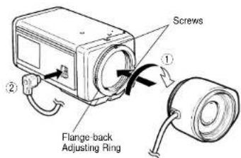
(5) Flange-back Adjusting Ring
This ring adjusts the back-focal distance or picture focus.
6 Lens (option)
Camera Mounting Adapter
There is a hole for mounting the camera onto a mounting bracket. The camera is originally designed to be mounted from the bottom, but a top-mounting type is also available. To mount from the top, remove the mount adapter from the bottom of the camera by removing two fixing screws. Attach the mount adapter to the top as shown in the diagram, then mount the camera on the mounting bracket. Make sure that two original screws are used when mounting the mount adapter; longer type screws may damage inner components.
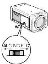
Lens Selector
Detach the cover from the camera and select the mode according to the lens type that is mounted on this camera.
ALC: Select this mode when an auto iris lens (ALC lens) is mounted on this camera.
NC: Not used.
ELC: Select this mode when a fixed iris lens or manual iris lens is mounted on this camera.
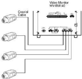
Coaxial Cable Connector
Connect a coaxial cable (to be procured locally) between this connector and the CAMERA IN connector of the specific monitor (or Camera Drive Unit).
Monitor supplies power to the camera, and the camera supplies the video output to the monitor through the coaxial cable.
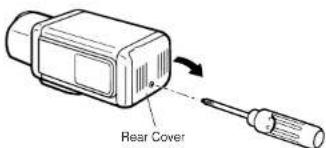
10 Bear Cover
The rear cover can be removed to gain access to the switches.
Back Light Compensation Mode Selector (BLC ON, OFF)
Select the mode according to the position of the object and light conditions.
When the ALC lens is mounted on this camera, select the mode with upper selector. When the fixed iris or manual iris lens is mounted, select with the lower selector.
ON: Select this mode when a strong light such as a spotlight is in the background.
OFF: Normal picture.
CONNECTIONS
Caution: Keep the POWER switch of the specified monitor, Camera Extension Unit and Camera Drive Unit in OFF position during connections. If the power of these units are ON during connections, the camera does not function due to protect circuit from misconnection.
Basic System
Connect the single coaxial cables between the Camera and Camera Input Terminal of Specified monitor or Camera Drive Unit. The approx. maximum cable length is as:
Coaxial Maximum DC R/1 000 ft. Cable Cable of Inner Type Length Conductor
RG-59/U 200 m (660 ft) Less than 30Ω RG-6/U 500 m (1 650 ft) Less than 12Ω
The maximum DC resistance between the camera and these units is 20Ω.
- Connection Diagram
Mounting the Lens
Caution:
Before you mount the lens, loosen the two screws on the ring, and rotate this ring clockwise until it stops. If the ring is not at the end, the inner glass or CCD image sensor may be damaged.
① Mount the lens by turning it clockwise on the lens mount of the camera.
② Connect the lens cable to the auto iris lens connector on the side of the camera.
Caution for Mounting the Lens
The lens mount should be a C-mount or CS-mount (1"32UN) and the lens weight should be less than 450g (0.99 lbs). If the lens is heavier, both the lens and camera should be secured by using the supporter.
The protrusion at the rear of the lens should be as shown in the diagram.
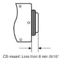
Caution: To use the C-mount lens, the Lens Mount Converter (C-mount adapter) WV-AD20 should be used with the camera.
FOCUS OR FLANGE-BACK ADJUSTMENT
The following adjustment should be made by qualified service personnel or system installers.
Loosen the screws on the flange-back adjusting ring.
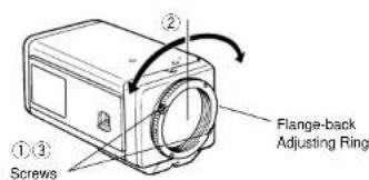
Turn the flange-back adjusting ring to the desired position.
Caution: Do not rotate the ring counterclockwise by force after it stops. If the ring is rotated by force, the inner lens or CCD image sensor may be damaged.
3 Tighten the screws on the flange-back adjusting ring.
INSTALLING PROCEDURE
The mounting bracket can be fixed either on the top or the bottom cover of the camera.
When mounting on the top cover of the camera, detach the mount adapter from the bottom of the camera cover and attach it on the top cover of the camera.
- Fix the camera mounting bracket on the wall or ceiling to be installed by two screws (to be procured locally).
- Insert the camera fixing screw on the pan head into the camera mounting adapter, and tighten the pan head firmly.
- Connect the camera and the monitor with the coaxial cable (to be procured locally).
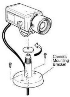
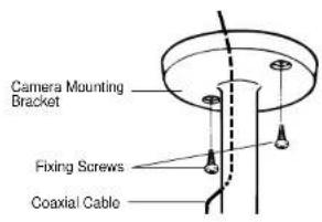
Note: Coaxial cable can be passed through the center hole of the camera mounting bracket.
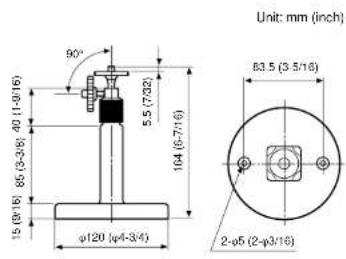
DIMENSIONS OF MOUNTING BRACKET
Cautions on Installation
Use wood screws with the camera mounting bracket that are suitable for Installation into a wood base of appropriate dimensions and strength. For the installation into a material other than wood, refer servicing to qualified service personnel.
SPECIFICATIONS
Pick-up Device: 512 (H) x 582 (V) pixels. Interline Transfer CCD
Scanning Area: 4.8 (H) x 3.6 (V) mm (Equivalent to scanning area of 1/3^ pick-up tube
Synchronization: Multiplexed vertical drive (VD2) by pulse from specified camera drive unit.
Scanning System: 2 : 1 Interlace
Scanning: 625 lines / 50 fields / 25 frames
Horizontal: 15.625 kHz
Vertical: 50 Hz
Horizontal Resolution: 380 lines
Video Output: 1.15 V[p-p] composite 75Ω
Signal-to-Noise Ratio: 46 dB (AGC OFF, weight ON)
Electronic Light Control: Equivalent to continuous variable shutter speed between 1/50 s
and 1/80 000 s
Minimum Illumination: 0.08 lx (0.008 foot-candle) at F1.4
Lens Mount: CS-mount
Ambient Operating Temperature: -10^ + 50^ (14°F - 122°F)
Ambient Operating Humidity: Less than 9
Power Source: From WV-PS11B/WV-PS104C
Dimensions (without lens): 71 (W) x 65 (H) x 125.5 (D) mm
[2-25/32" (W) x 2-9/16" (H) x 4-15/16" (D)]
Weights (without lens): 0.47 kg (1.03 lbs)
Weights and dimensions indicated are approximate.
Specifications are subject to change without notice.
STANDARD ACCESSORIES
Body Cap. 1 pc
Camera Mounting Bracket 1 pc.
OPTIONAL ACCESSORIES
Lenses: WV-LA2R8C3B, WV-LA4R5C3B, WV-LA9C3B, WV-LA210C3, WV-LA408C3, WV-LA908C3
WV-LZ61/10,WV-LZ62/2,WV-LZ62/8,WV-LF4R5C3A,WV-LF9C3A,WV-LFY3C3,WV-LFY45C3
WV-LFY9C3
Lens Mount Converter (C-mount Adapter): WV-AD20
Camera de "CCTV"
WV-BP50E
Horizontal:15.625kHz
Vertical: 50 Hz
71(L)×65(H)×125.5(P)mm
Dimensions [sans 100] Poids (sans 1 objectif):
0.47kg
Objectifs: WV-LA2R8C3B, WV-LA4R5C3B, WV-LA9C3B, WV-LA210C3, WV-LA408C3, WV-LA908C3
WV-LZ61/10.WV-LZ62/2.WV-LZ62/8.WV-LF4R5C3A.WV-LF9C3A.WV-LFY3C3.
WV-LEY45C3.WV-LEY9C3
Monture intermediale d'objectif (monture intermediale de type C): WV-AD20
