
EXR 1541 - Digital decoder KATHREIN - Free user manual and instructions
Find the device manual for free EXR 1541 KATHREIN in PDF.
| Product type | Single-cable multiswitch for satellite distribution |
| Brand | Kathrein |
| Model | EXR 1541 |
| Reference | 20510048 |
| Subscriber connections | 1 x 4 (4 receivers) |
| Inputs | 1 x terrestrial (5-862 MHz), 4 x Sat IF (950-2150 MHz) |
| Subscriber frequencies / SCR addresses | Receiver 1: 1284 MHz / 0; Receiver 2: 1400 MHz / 1; Receiver 3: 1516 MHz / 2; Receiver 4: 1632 MHz / 3 |
| Power supply | Mains adapter NCF 18 (included), input 220-230 V~, output 18 V ---, max. 650 mA |
| Permissible supply voltage at subscriber output | 10-14 V |
| Maximum switch consumption at 14 V | 110 mA |
| Max. remote power supply current (via low horizontal input) | 650 mA |
| Transmission attenuation (terrestrial path) | 1 dB |
| Gain at subscriber connection (SAT) | -1 to +3 dB depending on frequency |
| Horizontal/vertical decoupling | ≥ 30 dB |
| Dimensions (W x H x D) | 112 x 148 x 44 mm |
| Weight (with NCF 18 adapter) | 0.45 kg |
| Permissible ambient temperature | -20 to +55 °C |
| Connections | F connectors 75 Ω |
| Installation | Indoor, do not mount on ceiling; ventilation at least 5 cm on each side |
| Standards | Compliant with EN 50494 (SCR single-cable), EN 60728-11, EN 60065 |
| Receiver compatibility | SCR single-cable compatible receivers according to EN 50494 |
| Maintenance and cleaning | Disconnect the mains adapter before any intervention; do not expose to humidity; clean with a dry cloth |
| Safety | Do not open; surge protection recommended; equipotential bonding (Cu 4 mm² min.); do not place liquids on the adapter |
| Spare parts and repairability | NCF 18 mains adapter (ref. 20510046) available; standard F connectors; no user-serviceable parts |
Frequently Asked Questions - EXR 1541 KATHREIN
User questions about EXR 1541 KATHREIN
0 question about this device. Answer the ones you know or ask your own.
Ask a new question about this device
Download the instructions for your Digital decoder in PDF format for free! Find your manual EXR 1541 - KATHREIN and take your electronic device back in hand. On this page are published all the documents necessary for the use of your device. EXR 1541 by KATHREIN.
USER MANUAL EXR 1541 KATHREIN
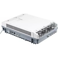
- Cascadable single-cable multi-switch for distribution of digital Sat-IF signals (4 sat levels; including HDTV) and terrestrial signal for supplying 4 receivers in single-family households
No restriction on the variety of channels - the complete range of channels from one satellite is transmitted
Option to select horizontal/vertical, low band/high band and transponder independently from each receiver
Changeovers horizontal/vertical, low band/high band and transponder selection is carried out in the multi-switch, controlled by the receiver with a special SCR single-cable command set to EN 50494
For transponder selection special tuning modules called SCRs (Satellite Channel Routers) are incorporated in the single-cable multi-switch for conversion to the subscriber frequencies
Each receiver is assigned a fixed subscriber frequency (a twin receiver requires two subscriber frequencies)
The unit satisfies the SCR single-cable standard to EN 50494, i.e. all components of a single-cable system that satisfy this standard can be installed in a satellite system
Terrestrial signals can be received even when the satellite receiver is switched off
EXR 2541 single-cable multi-switches and loop-through multi-switches such as the EXR 2558 can be mixed in any combination. Up to 8 multi-switches can be connected in a cascade
For indoor mounting
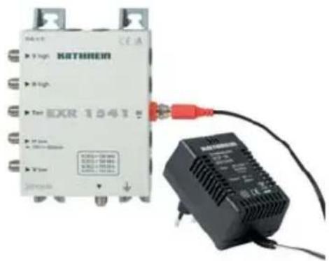
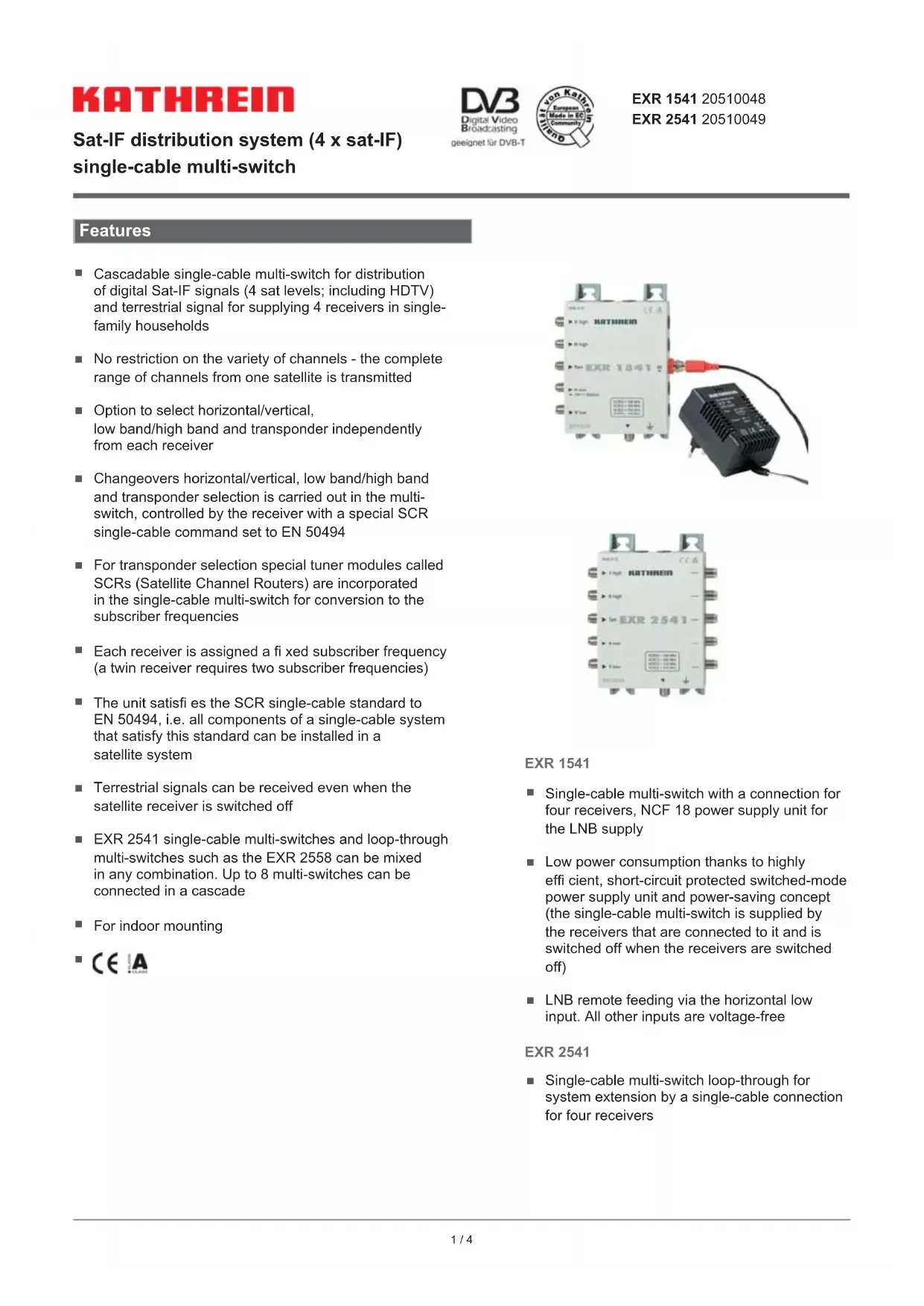
EXR 1541
Single-cable multi-switch with a connection for four receivers, NCF 18 power supply unit for the LNB supply
Low power consumption thanks to highly efficien, short-circuit protected switched-mode power supply unit and power-saving concept (the single-cable multi-switch is supplied by the receivers that are connected to it and is switched off when the receivers are switched off)
LNB remote feeding via the horizontal low input. All other inputs are voltage-free
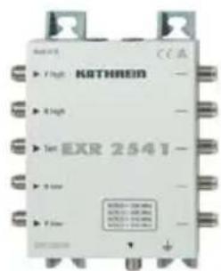
EXR 2541
Single-cable multi-switch loop-through for system extension by a single-cable connection for four receivers
Installation and safety instructions

- The equipment described is designed solely for installation in satellite receiver systems.
- Any other use, or failure to comply with these instructions, will result in voiding of warranty cover.
- The equipment may only be installed in dry areas indoors. Do not mount it on or against easily flammable materials.
- The equipment must be provided with an equipotential bonding wire (Cu, at least 4 mm2).
- The safety regulations set out in the current EN 60728-11 and EN 60065 standards must be complied with.
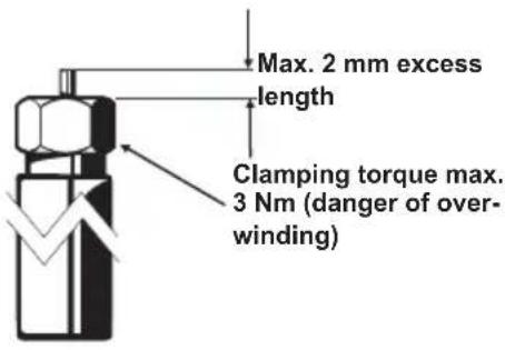
Fixings: Wood screws, max 0: 4.5 mm - Connector: RF plug 75 Ω (series F) to EN 61169-24.
- In order to satisfy the EMC requirement, the only power supply unit that may be used for the EXR 1541 is the NCF 18.
- Unused RF connections must be terminated with 75 - Ω resistors (such as EMK 03).
Current-carrying device NCF 18
- Do not open the unit or tamper with it!
- When working on the system always unplug the power supply unit from the wall socket!
- Ensure adequate clearance! Clearance all round at least 5 cm!
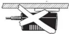
- The unit must not be mounted on the ceiling!
- Free circulation of air must be possible to discharge the heat emitted by the unit. Danger of overheating!
- Ambient temperature range -20 to +55°C
Caution:
- No liquid-filled items may be placed on top of the power supply unit.
- The power supply unit must not be exposed to dripping or splashing water.
-
In order to disconnect the unit from the mains it is necessary to unplug it at the wall socket, which must therefore be easily accessible.
-
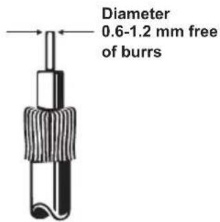
An inner cable conductor diameter greater than 1.2mm , or the presence of burrs may damage the sockets on the unit.
Notes
- Particular care should be taken to assign each of the frequencies available at the output from the multi-switch to only a single receiver, otherwise the receivers will generate mutual interference.
The frequencies are allocated on the receiver's setting menu. - Depending on the type, this may be performed manually or automatically.

- It is recommended that the wall sockets with the shorter length connections are assigned to the higher frequencies.
- By definition the system is designed so that single-cable units are supplied with 14VDC
- The power supply is briefly switched to 18V DC if control signals similar to DiSEqC™ have to be transmitted. Continuous application of 18V would block the system. For this reason we recommend the use of ESU 33/34 sockets, which are equipped for switching off electronically.
The receivers that are connected must be designed for single-cable operation to EN 50494.
System example (symbolic representation)
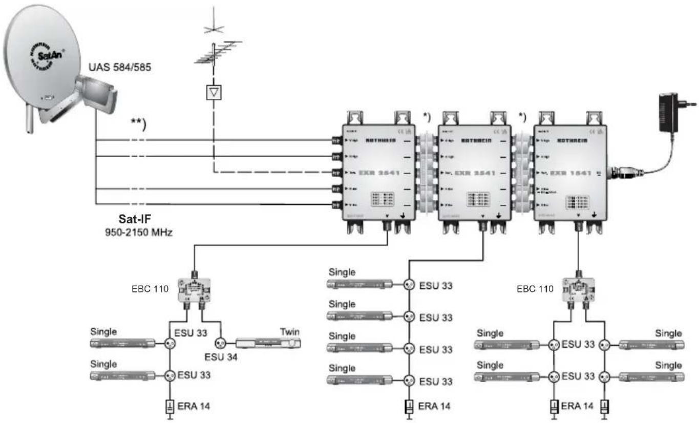
4 connections per living unit
* EMU 250 (5-way plug connector), BN 20510044 available as an option. Not supplied with the EXR 1541/2541
**) KAZ 11/KAZ 12 overvoltage protector
SCR single-cable commands for various programs
| Programme BBC EIN | S EXTRA PRO 7 QVC | |||
| Sat IF level Vertical low Horizontal low Horizontal high Vertical high | ||||
| 1847 MHz 994 MHz 1945 MHz 1952 MHz | ||||
| E0 10 5A .... E0 10 5A .... E0 10 5A .... E0 10 5A .... | ||||
| SCR 0 (1284 MHz) 01 | B1 08 DB 0D CA 05 CB | |||
| SCR 1 (1400 MHz) | 21 CE 28 F8 | 2D E7 25 E8 | ||
| SCR 2 (1516 MHz) | 41 EB 49 15 4E 04 | 46 05 | ||
| SCR 3 (1632 MHz) | 62 08 | 69 32 | 6E 21 | 66 22 |
As at: Dec 2010 The following applies for the channels listed: SR-FEC 22000-5/6
Possible causes of faults, and their remedies
| Problem | Possible cause: | Solution |
| Multi-switch fails to switch | No control signal from receiver, or incorrect control signal | Check that there are no short circuits in the connection from the receiver to the multi-switch. Check the menu settings of the receiver (in single-cable mode!). Operating voltage at the receiver output must not exceed 14 V |
| Multi-switch operates, but no associated picture appears | Incorrect input cable frequency | Check menu settings of all connected receivers. Check that frequencies are assigned to one receiver only |
Technical Specification
| Type EXR 1541 EXR 2541 | ||||||
| Order no. 20510048 20510049 | ||||||
| Subscriber connections 1 x 4 1 x 4 | ||||||
| Inputs 1 x terrestrial 4 x sat-IF 1 x terrestrial 4 x sat-IF | ||||||
| Frequency range MHz 5-862 950-2150 5-862 950-2150 | ||||||
| Through loss dB - 2.5 | 1.5 | |||||
| Connection loss (terrestrial) | dB | 1 | - | 7 | - | |
| Gain to the subscriber connection (SAT)1 | dB | - | -1 → 3 | - | -1 → 3 | |
| Horizontal/vertical isolation | dB | - | 30 | - | 30 | |
| Trunk decoupling | dB | - | - | - | 40 | |
| Operational level | dBμV | - | 85 | - | 85 | |
| Subscriber frequency/SCR address | Receiver 1 | MHz | 1284/0 | 1284/0 | ||
| Receiver 2 | 1400/1 | 1400/1 | ||||
| Receiver 3 | 1516/2 | 1516/2 | ||||
| Receiver 4 | 1632/3 | 1632/3 | ||||
| Permissible supply voltage at the subscriber output | V | 10-14 | 10-14 | |||
| Max. power consumption of multi-switch at 14 V | mA | 110 | 110 | |||
| Max. total remote feed current2) | mA | 650 | - | |||
| Max. remote feed current per trunk | mA | - | 1000 | |||
| Permissible ambient temperature | °C | -20 to +55 -20 to +55 | ||||
| Connections | F connectors | F connectors | ||||
| Dimensions | mm | 112 x 148 x 44 | 112 x 148 x 44 | |||
| Packing unit/weight | pc./kg | 1 (10)/0.45 (incl. NCF 18) | 1 (10)/0.31 | |||
1) Frequency-dependent attenuation/gain (pre-emphasis); additional SCR 0: -1 dB, SCR 3: +2 dB
2) Via horizontal low input
Technical data for the NCF 18 power supply unit (only for EXR 1541)
| Type | NCF 18 | |
| Order no. | 20510046 | |
| Nominal input voltage | V~ | 220-230 (50/60 Hz) |
| Nominal input power at 10/150/650 mA load | W | 1.6/4.7/14.5 |
| Secondary voltage (short-circuit proof) | V --- | 18 |
| Nominal secondary voltage | mA --- | Max. 650 |
| Protection class/protection type | II (double insulated)/IP 30 | |
| Permissible ambient temperature | °C | -20 to +55 |
| DC connection | F connector | |
| Dimensions | mm | 55 x 80 x 75 |
Electronic equipment is not domestic waste - it must be disposed of properly in accordance with directive 2002/96/EC OF THE EUROPEAN PARLIAMENT AND THE COUNCIL dated 27th January 2003 concerning used electrical and electronic appliances. At the end of its service life, take this device for disposal at a designated public collection point.
\section*{Caracteristique}


Brand : KATHREIN
Model : EXR 1541
Category : Digital decoder