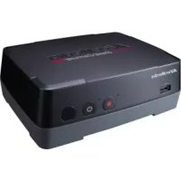
Game Capture HD - Voice recorder AVERMEDIA - Free user manual and instructions
Find the device manual for free Game Capture HD AVERMEDIA in PDF.



User questions about Game Capture HD AVERMEDIA
0 question about this device. Answer the ones you know or ask your own.
Ask a new question about this device
Download the instructions for your Voice recorder in PDF format for free! Find your manual Game Capture HD - AVERMEDIA and take your electronic device back in hand. On this page are published all the documents necessary for the use of your device. Game Capture HD by AVERMEDIA.
USER MANUAL Game Capture HD AVERMEDIA
Please read all of the safety precautions before using the product.
The following symbols are used to indicate important information:
CAUTION:

The exclamation point within an equilateral triangle is intended to alert the user to the presence of important operating and maintenance (servicing) instructions in the documentations accompanying the appliance.
WARNING:

The lightning flash with arrowhead symbol, within an equilateral triangle, is intended to alert the user to the presence of uninsulated “dangerous voltage” within the product’s enclosure that may be of sufficient magnitude to constitute a risk of electric shock to persons.

Precautions on Power
- Do not plug too many devices into a socket. It may cause an overload and result in an electric shock or fire.
- Do not touch the plug with wet hands. It may cause an electric shock or fire.
- Do not place heavy objects on the power cable or bend it severely. It may cause a fire.
- Keep the product away from moisture and dust. It may cause an electric shock and fire.
- Please disassemble the product after turning it off. Do not disassemble the product while the power is on. It may cause an electric shock or bum.

Installation Precautions
- Do not install around any heat sources such as radiators, heat registers, or cooking appliances.
- Do not place any magnetic objects around the product. It may damage the data in your HDD. We will not be liable in any way for damages as a consequence of loss or recovery of information in the HDD.
- Do not drop the product or cause it to be subject to severe impact on it. It can cause the product to malfunction.
● Make sure that the product is powered off before any attempt to connect the power and A/V cables. - Do not alter the product. It can cause a fire and will void the warrantee.

Usage Precautions
We are not liable for any personal or confidential information stored in the HDD if it is damaged by strong impact or abuse. Customers should back up their data before returning the unit for repair.
- Do not cause any strong impact to the product. The HDD or the product itself can be damage and malfunction.
- Do not connect the cables when the product is on.

Precautions on HDD
- When detaching a HDD which has recently been used, please wait for the unit to cool. A hot HDD can cause a serious burn.

Maintaining the Product
● Never clean the product with furniture wax, benzene or other volatile liquids since they may corrode the cabinet.
- Please clean the product with dry & soft cloth after unplugging the power adapter.
- Do not turn off the product while upgrading firmware (F/W). It may cause malfunction.
Important Safety Instructions
Read these operating instructions carefully before using the unit. Follow the safety instructions on the unit and the applicable safety instructions listed below. Keep these operating instructions handy for future reference.
- Read these instructions.
- Keep these instructions.
- Heed all warnings.
- Follow all instructions.
-
Do not use this apparatus near water.
-
Clean only with dry cloth.
-
Do not block any ventilation openings. Install in accordance with manufacturer instructions.
-
Do not install near any heat sources such as radiators, heat registers, stoves, or other apparatus (including amplifiers) that produce heat.
-
Do not defeat the safety purpose of the polarized or grounding-type plug. A polarized plug has two blades with one wider than the other. A grounding type plug has two blades and a third grounding prong. The wide blade or the third prong are provided for your safety. If the provided plug does not fit into your outlet, consult an electrician for replacement of the obsolete outlet.
-
Protect the power cord from being walked on or pinched particularly at plugs, convenience receptacles, and the point where they exit from the apparatus.
-
Only use attachments/accessories specified by the manufacturer.
-
Unplug this apparatus during lightning storms or when unused for a long period of time.
-
Refer all servicing to qualified service personnel. Servicing is required when the apparatus has been damaged in any way, such as power-supply cord or plug is damaged, liquid has been spilled or objects have fallen into the apparatus, the apparatus has been exposed to rain or moisture, does not operate normally, or has been dropped.
-
Use only with cart, stand, tripod, bracket, or table specified by the manufacturer, or sold with the apparatus. When a cart is used, use with caution when moving the cart/apparatus combination to avoid injury from tip-over.

Battery Safety Information
● Store the batteries in a cool dry place.
- Do not dispose of used batteries in domestic waste. Dispose of batteries at special collection points or return to point of sale if applies.
- Remove the batteries during long periods of non-use. Always remove exhausted batteries from the remote control. Battery leakage and corrosion can damage this remote control, dispose of batteries safely.
- Do not mix old and new batteries.
- Do not mix different types of batteries: alkaline, standard (carbon-zinc) or rechargeable (nickel-cadmium).
- Do not dispose of batteries in a fire. The batteries may explode or leak.
● Never short circuit the battery terminals.
European Community Compliance Statement

Class B
This product is herewith confirmed to comply with the requirements set out in the Council Directives on the approximation of the laws of the Member States relating to Electromagnetic Compatibility Directive (EMC) 2004/108/EC, Low Voltage Directive (LVD) 2006/95/EC and Energy-related Products Directive (ErP) 2009/125/EC.
WASTE ELECTRICAL AND ELECTRONIC EQUIPMENT (WEEE)
The mark of Crossed-out wheeled bin indicates that this product must not be disposed of with your other household waste. Instead, you need to dispose of the waste equipment by handing it over to a designated collection point for the recycling of waste electrical and electronic equipment. For more information about where to drop off your waste equipment for recycling, please contact your household waste disposal service or the shop where you purchased the product.
FCC Compliance Statement (United States)

FCC Class B Part 15
This device complies with Part 15 of the Federal Communications Commission (FCC) Rules. The FCC ID for this device is L6ARCR10BW. Operation is subject to the following two conditions:
● This device may not cause harmful interference.
● This device must accept any interference received, including interference that may cause undesired operation.
CAUTION:
Changes or modifications to this unit not expressly approved by the party responsible for compliance could void the user's authority to operate this equipment.
This equipment has been tested and found to comply with the limits for a Class B digital device, pursuant to Part 15 of the FCC Rules. These limits are designed to provide reasonable protection against harmful interference in a residential installation. This equipment generates, uses and can radiate radio frequency energy and, if not installed and used in accordance with the manufacturer's instructions, may cause interference harmful to radio communications.
There is no guarantee, however, that interference will not occur in a particular installation. If this equipment does cause harmful interference to radio or television reception, which can be determined by turning the equipment off and on, the user is encouraged to try to correct the interference by one or more of the following measures:
● Reorient or relocate the receiving antenna.
- Increase the separation between the equipment and receiver.
- Connect the equipment to an outlet on a circuit different from that to which the receiver is connected.
- Consult the dealer or an experienced radio or TV technician for help.
ICES-003 (Canada)
"This B digital apparatus complies with Canadian ICES-003."
BSMI Registration of Product Certification (Taiwan)

R33183
KCC Class B Statement (Korea)

KCC-REM-AVM-C281
GOST-R Certification (Russia)

AB29
No POCC TW.AB02.B05687
Срок действия
©2012 by AVerMedia Technologies, Inc. All rights reserved. No part of this document may be reproduced or transmitted in any form, or by any means (Electronic, mechanical, photocopy, recording, or otherwise) without prior written permission of AVerMedia Technologies, Inc.
Information in this document is subject to change without notice. AVerMedia Technologies, Inc. reserves the right to modify, change, improve or enhance its products and to make changes in the content without obligation to notify any person or organization of such changes. Please visit avermedia.com to get the updates of the operation and use of AVerMedia products.
"AVerMedia ^* " is trademark and logo of AVerMedia Technologies, Inc. Other trademarks used herein for description purpose only belong to each of their companies.
Picture shown may vary from actual product.
This product uses Arphic Font.
This software uses libraries from the Libav project under the LGPLv2.1.

International Headquarter Office
Address No.135, Jian 1st Rd., Zhonghe Dist., New Taipei City 23585, Taiwan (R.O.C.)
Website www.avermedia.com/
Tel +886-2-2226-3630
Specifications
| Product Name | Game Capture HD (HD 錄影盒) |
| Model No. | C281 |
| Power | |
| Input Rating | 12V---1.5A |
| Power Consumption | < 7W (power consumption of hard drive not included) |
| Standby Power Consumption | < 1W |
| Adapter Rating | Input: 100-240V~, 50-60Hz 0.5A Max. Output: 12V---1.5A |
| Dimension | |
| Size | 164 mm(W) x 57 mm (H)x 124 mm (D) |
| Weight | 335 g |
| Environmental Condition | |
| Operating Temperature | 0~40°C |
System Requirements
● TV/monitor with component video (YPrPb) input
● TV/monitor with 720p or 1080i resolution (recommended)
● Game console/video device with component video (YPrPb) output
- NTFS-formatted hard drive with capacity greater than 320 GB is recommended (The supported maximum storage capacity of the hard drive is 2TB.)
● Hard drive is highly preferred over flash drive to minimize the risk of recording failure
Table of Content
Chapter 1 Package Contents ...... 2
Chapter 2 The Unit Parts....4
2.1 Touch Button Control Panel 4
2.2 Infrared Sensor....4
2.3 LED Indicator....5
2.4 Connection Ports 6
2.4.1 Front View....6
2.4.2 Rear View....6
Chapter 3 Installation & First Time Setup ....7
3.1 Hardware Installation....7
3.2 Storage Device Installation 12
3.2.1 USB Storage Device Insertion....12
3.2.2 HDD Installation and Removal....12
3.3 Setup Wizard 17
3.4 Supported Resolutions ......20
3.5 Video Output Settings for Game Consoles 20
3.5.1 Video Output Settings for PS3....20
3.5.2 Video Output Settings for Xbox 360....23
Chapter 4 The Remote Control....24
Chapter 5 Gameplay Capture 26
5.1 Live Preview Screen (Standard Mode & Real-time Mode)......26
5.2 Gameplay Capture on Standard Mode 27
5.3 Gameplay Capture on Real-time Mode 29
Chapter 6 The OSD Menu Display....29
6.1 Recordings and Snapshots....30
6.2 File Management....32
6.3 Settings....36
Appendix A How to Set Your Gameplay Snapshot as PS3 Wallpaper......40
Thank you for purchasing the Game Capture HD. Please read this user manual carefully to ensure proper use of this product. We recommend you to keep it for future reference.
Introduction
The Game Capture HD, a stand-alone video capture box specially designed for TV gamers, allows you to capture HD content up to 1080i from various video game consoles, such as PlayStation®3 and Xbox 360.
The Game Capture HD records HD gameplays directly to your hard disk drive (HDD) for later viewing and further editing, eschewing the hassle of setting up a PC nearby your TV set.
Most attractively, the one-press capture feature allows you to instantly grab high score screen and record your exciting gameplay footage with nearly no effort.
Chapter 1 Package Contents
Please confirm that the package contains the following items. If any of the package contents are missing or damaged, please contact the distributor immediately.
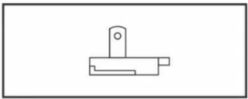
text_image
AVerMediaGame Capture HD

natural_image
Pure electrical circuit lines without any symbolsPower Adapter
natural_image
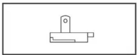
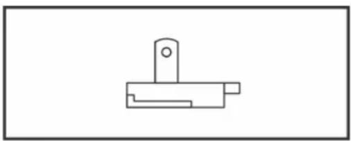
Simple line drawing of a mechanical bracket or clamp (no text or symbols)Power Adapter Outlet Module
natural_image
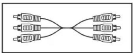
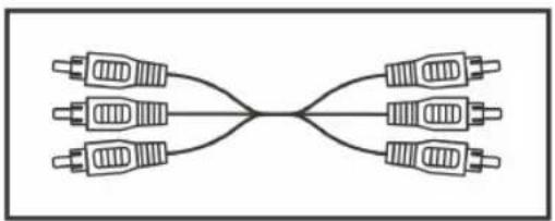
Pure electrical circuit lines without any symbolsComponent Video Cable
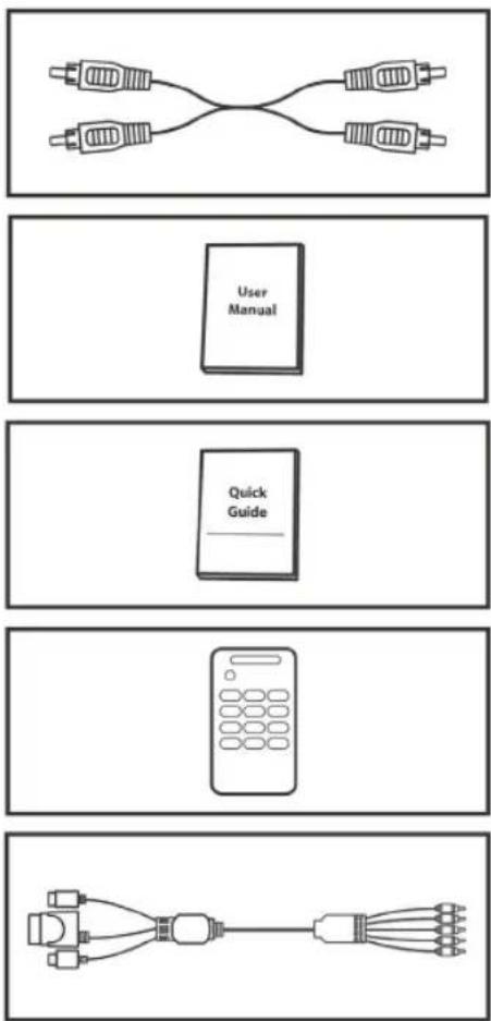
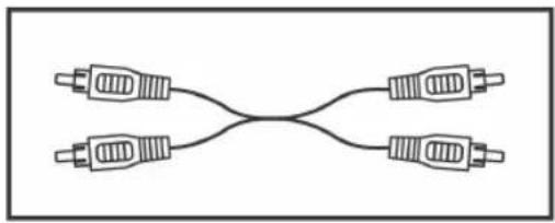
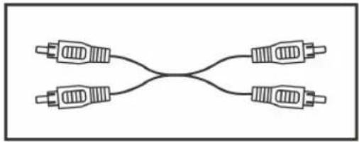
RCA Audio Cable
User Manual
Quick Guide
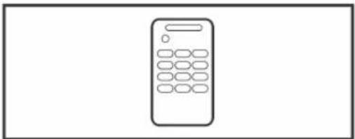
Remote Control (Batteries Included)
Universal Component Cable for Game Consoles

● The accessories that come with the package may slightly vary depending on different sales regions.
- AVerMedia regularly releases the latest version of firmware for the Game Capture HD. Having the latest firmware enhances the functionality of the Game Capture HD To download the latest firmware file, please go to /www.avermedia.com and then enter the model name in Product Search field. Firmware file is available on the product information page. (See p.39 for details)
Chapter 2 The Unit Parts
2.1 Touch Button Control Panel
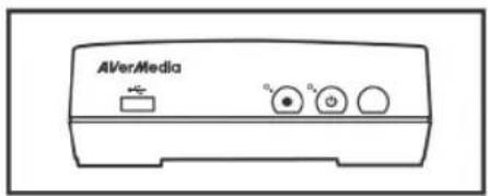
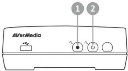
The touch button panel found on the front of the unit provides quick access to commonly used functions
text_image
AVerMedia 1 2#
Buttons
Descriptions
1

Record
Press to start / stop recording.
2

Power
Press to turn the unit on / into stand-by mode.
2.2 Infrared Sensor
When using the remote control, aim it at the infrared (IR) sensor located at the front panel of the unit. The remote control must be held at an angle within 30 degrees perpendicular to the IR sensor to function correctly. The distance between the remote control and the sensor should not exceed 6 meters (20 feet).
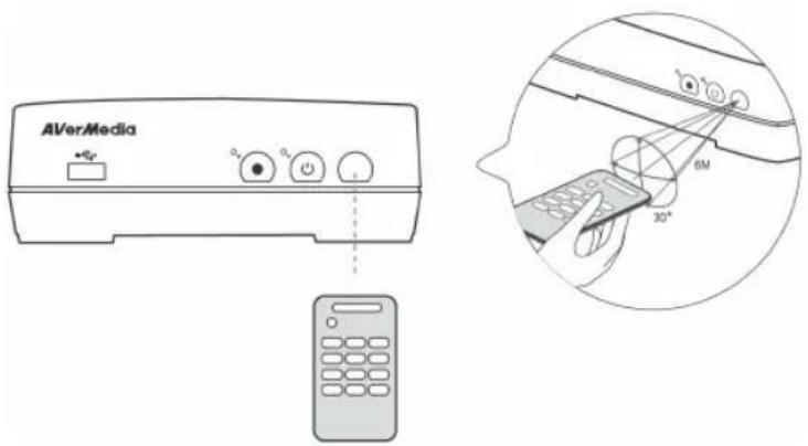
text_image
AVerMedia 6M 30°2.3 LED Indicator
The LED indicators on the front of the unit show the device's status.
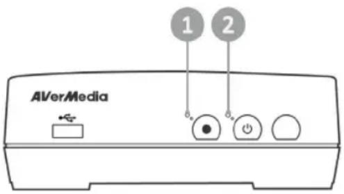
text_image
1 2 AVerMedia1 Red LED indicator
2 Green / Blue LED indicator
While the device is...
On (Standard Mode)
On (Real-time Mode)
Off / in standby mode
Starting up / Powering off / Upgrading its firmware
Having problems
Receiving a remote control signal
(Standard Mode)
Receiving a remote control signal (Real-time Mode)
While the device is...
Under recording mode
Accepting a snapshot command
The Green/Blue LED indicator...
Glows solid green
Glows solid blue
Lights off
Flashes green continuously
Alternates between green and blue
Flashes green once
Flashes blue once
The Red LED indicator...
Flashes red continuously
Flashes red once

2.4 Connection Ports
2.4.1 Front View
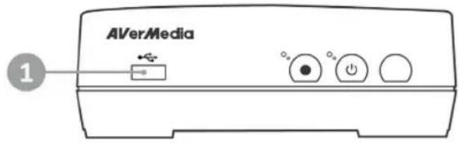
text_image
AVerMedia 11 USB slot

- USB slot is for external USB storage device connection as well as for firmware upgrade via USB storage device.
- USB hub is not supported.
2.4.2 Rear View
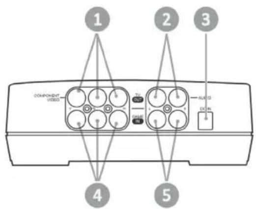
text_image
COMPONENT VIDEO ALABO DUN 1 2 3 4 51 Component video output
2 RCA Audio L/R output
3 DC-IN
4 Component video input
5 RCA Audio L/R input
Chapter 3 Installation & First Time Setup
3.1 Hardware Installation
Please follow the steps below to properly connect the Game Capture HD and your TV / video game consoles.

- The Game Capture HD supports one game console connection at a time only. Connecting more than one console to the Game Capture HD at the same time may result in video quality issues, even if only one console is on.
- Before making the connections, make sure to set game console's video output to "Component" and adjust its output resolution to 1080i or below. Then power your game console off.
- If you would like to install internal hard drive, install it before making the connections.
- Make sure that the cables are firmly connected and that neither of the cables are loose. If any of the cables are loose or disconnected, there may be a loss of signal or screen color problems.
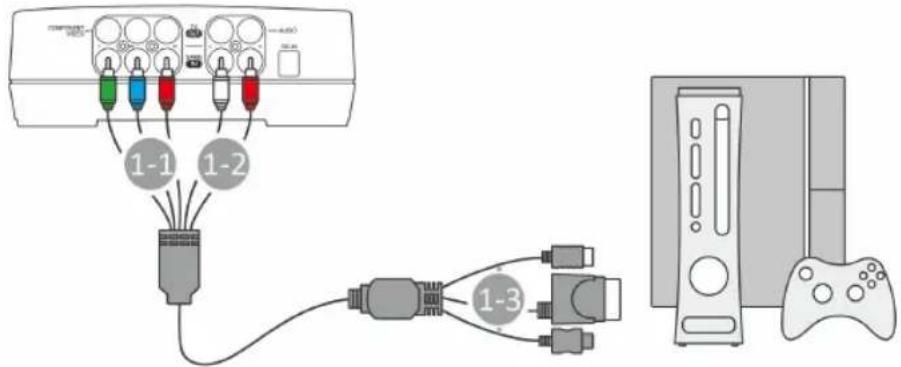
Step 1 Connecting the Device to Your Game Console Using Universal Component Cable
Universal Component Cable is used to hook up your game console to the Game Capture HD at a time.
This cable is composed of component video cable with RCA audio cable at one end and three cables compatible with PS2/3, Xbox and Wii at the other end.
Step 1-1:
Plug the green, blue, red connectors into the COMPONENT VIDEO IN port on the rear of the device.
Step 1-2:
Plug the white and red connectors into the AUDIO IN port on the rear of the device.
Step 1-3:
Plug the other end to your game console (choose a console-specific cable).
text_image
1-1 1-2 1-3
Make sure not to mix up the two red cables.

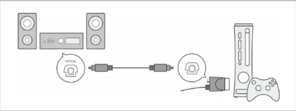
When connecting with the Game Capture HD, your console's audio output settings remain unchanged. If your amplifier or other audio devices support optical digital audio output, you can still output digital audio. Please follow the steps below to make digital audio cable connection and configure the audio output settings.
For Xbox 360:
Step 1
Connect one end of the digital audio cable (not included) to the DIGITAL AUDIO OUTPUT port on the Universal Component Cable. Then connect the other end to the DIGITAL AUDIO INPUT (OPTICAL INPUT) port on your amplifier or surround system.
text_image
Diagram showing connected devices including a 888 speaker, optical connector, and game controller with labeled components.Step 2
On your console, go to Settings > Console Settings > Audio > Digital Output and select the appropriate digital audio setting for your amplifier or surround system.
For PS3:
Step 1
Connect your console with amplifier or surround system via digital audio cable (not included)
Step 2
On your console, go to Settings >Sound Settings > Set Audio Output Settings and select "Optical Digital". Then select "Dolby Digital 5.1 Ch.".
Step 3
On your console, go to Settings > Sound Settings > Audio Multi-Output and set the option to "On".

Step 2
Connecting the Device to Your TV Using Component Video Cable
Connect one end of the component video cable to the COMPONENT VIDEO OUT port on the rear of the device and the other end to the COMPONENT VIDEO IN (colored green, blue, and red) port on your TV.

text_image
Y Pv/Cr Pv/Cr COMPANY "HOLD" A:100 B:200 C:300 D:400 E:500 F:600 G:700 H:800 I:900 J:1000 K:1100 L:1200Step 3 Connecting the Device to Your TV Using Composite Audio Cable
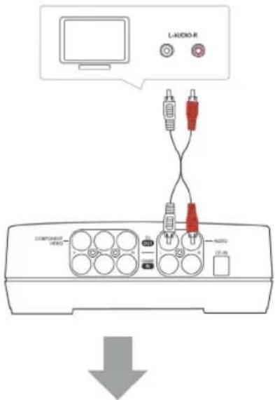
Connect one end of the composite audio cable to the AUDIO OUT port on the rear of the device and the other end to the AUDIO IN (colored white and red) port on your TV.
text_image
L-AUDIO-R COMPRESSOR VIDEO AUDIO 12.00Step 4 Powering on Your Game Console
Power on your game console.

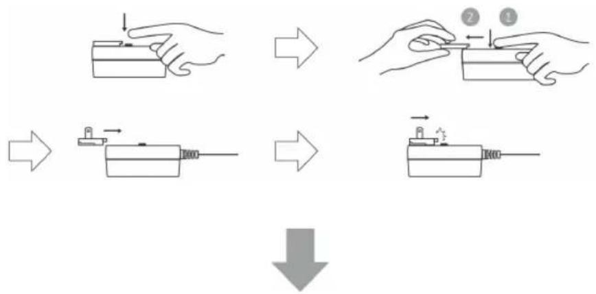
Step 5
Installing the Power Adapter
Slide the Power Adapter Outlet Module into the groove on the Power Adapter.
flowchart
graph TD
    A["Step 1: Hand press"] --> B["Step 2: Disassembly"]
    B --> C["Step 3: Hand press with tool"]
    C --> D["Step 4: Disassembly with tool"]
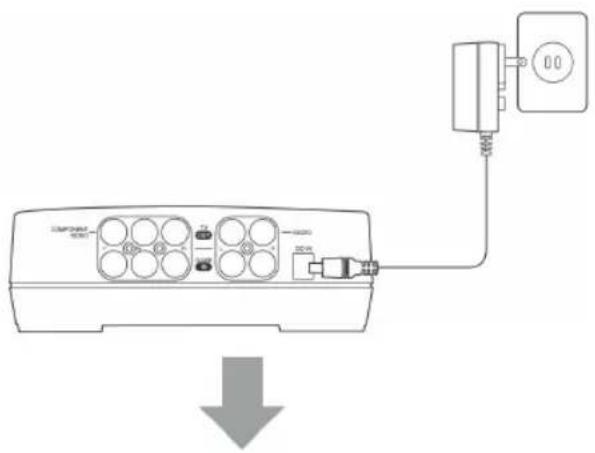
Step 6
Connecting the Power Adapter
Connect the Power Adapter connector to the DC-IN port on the rear of the device. Then plug the power adapter to a wall outlet.
text_image
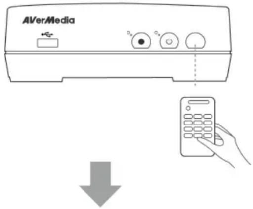
Diagram showing connection between a remote control unit and a power adapter, with a downward arrow indicating signal flow or download.Step 7
Powering on the Game Capture HD
Press the power button on the front panel of the device.
Or
Aim the remote control at the infrared sensor located on the front panel of the device. Then press
Power on the remote.
The LED indicator then lights up green, indicating that the device is on.
text_image
AVerMediaStep 8
Check Video on TV screen
Make sure that there is video displayed on TV screen.

If your TV is not displaying video properly, please check the followings:
- Make sure that your TV is set on the correct input source (COMPONENT IN). Switch video input by pressing the input selection button ("Input"/"Source"/"TV/AV") on the TV remote control. Supported resolutions vary depending on the TV in use. For details, please refer to the documentation that comes with your TV.
- Check video output settings of your game console. If you were using HDMI connection for your game console, reset the video output for your game console (See p.20 for details).
- Power off Game Capture HD and then make sure that the device is connected properly and with the proper cables.
- If there is still no video signal on TV, refer to FAQ section at www.avermedia.com for further troubleshooting.
3.2 Storage Device Installation
The Game Capture HD supports 2.5 inch internal hard drive (with both 9.5mm and 12.5mm height) and external USB storage device. You can save the recorded files and snapshots either to the internal HDD or your external USB drive.
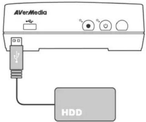
3.2.1 USB Storage Device Insertion
Connect your portable USB hard drive to the USB port on the front of the Game Capture HD
text_image
AVerMedia HDD
- It is highly recommended to use a hard drive instead of a flash drive to minimize the risk of recording failure.
- To avoid data loss, please safely remove your external storage device before unplug it from the Game Capture HD (See p.32 for details).
- If problems encountered while using USB flash drive to store recordings, refer to FAQ section at www.avermedia.com for further troubleshooting.
3.2.2 HDD Installation and Removal

- It is highly recommended to use a new unformatted hard drive or a hard drive formatted as NTFS file system. The maximum supported storage capacity of the hard drive is 2TB.
- Before installing or removing the internal HDD, please disconnect the power supply from the Game Capture HD to avoid data loss.
- Removing internal HDD immediately after powering-off may cause personal injury due to heat. Please wait until the HDD cools down completely (it takes approximately 10 minutes) before any attempt to remove it.
To install the internal HDD:
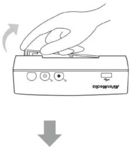
Step 1
Removing the HDD Lid
Use your fingertip to flip open the HDD lid, located on the bottom of the Game Capture HD.
Lift off the lid and set it aside.
natural_image
Line drawing of a hand pressing down on an Analog device labeled 'AverMedia' with control buttons, showing no text or symbols beyond the label.Step 2
Measuring HDD Height Using Measuring Card
Use the measuring card placed on the HDD slot to measure the height of your HDD (9.5mm or 12.5mm).
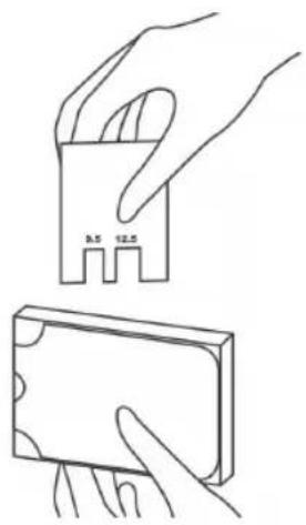
natural_image
Line drawing of two hands holding a small electronic component (no text or symbols)Step 3 Adjusting the Rotary Knob
Adjust the rotary knob attached to the inner side of the lid to fit the height of your HDD.
The default position of the rotary knob fits HDD with 9.5mm height. If you use HDD with 12.5mm height, rotate the rotary knob to the other direction.
Using a 9.5mm HDD:
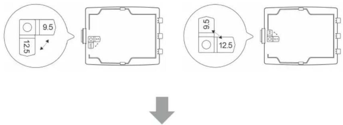
Using a 12.5mm HDD:
Step 4 Inserting the HDD
Place the HDD on the slot with the sticker-side facing up and the HDD connector end facing to the left.
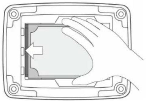
natural_image
Hand placing a component into a rectangular device frame (no text or symbols visible)Align and insert the HDD connectors all the way into the SATA connectors attached to the slot. Push in firmly to secure them.
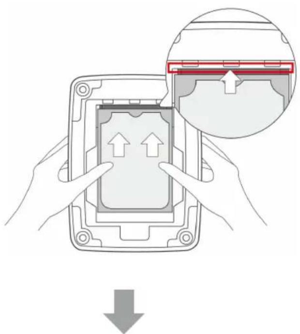
text_image
Diagram illustrating a device's internal processing step with directional arrows and a magnified view of the component.Step 5 Replacing the HDD Lid
Place the HDD lid back and snap it into place.
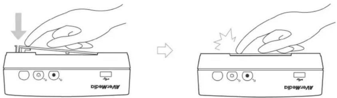
text_image
AverMedi AverMediTo remove the internal HDD:
Step 1
Removing the HDD Lid

Removing internal HDD immediately after powering-off may cause personal injury due to heat. Please wait until the HDD cools down completely (it takes approximately 10 minutes) before any attempt to remove it.
Use your fingertip to flip open the HDD lid, located on the bottom of the Game Capture HD.
Lift off the lid and set it aside.
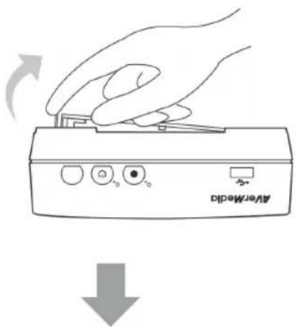
text_image
AerMediaStep 2
Removing the HDD
Pull the HDD out in the direction of the arrow. Then lift the HDD out of the slot.
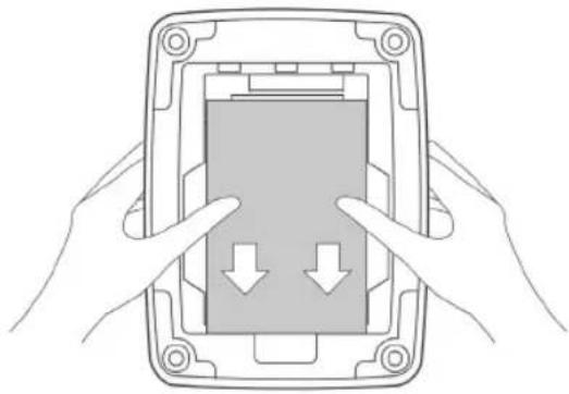
natural_image
Illustration of hands pressing down on a device panel with two downward arrows (no text or symbols)
Step 3
Replacing the HDD Lid
Place the HDD lid back and snap it into place.

natural_image
Illustration of a hand pressing down on an AirMed device with control buttons (no text or symbols)
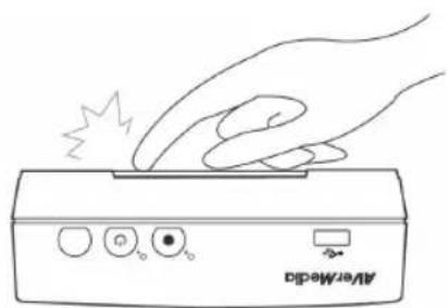
natural_image
Line drawing of a hand pressing a button on an electronic device labeled 'AverMedsid' (no other text or symbols)3.3 Setup Wizard
When the first time you power on the Game Capture HD unit, the setup wizard appears. The following steps guide you through the initial configuration process.

● Make sure to install internal hard drive or external USB storage device beforehand.
- For the first-time initialization, a short duration of black screen (approximately 20 seconds) is followed by AVerMedia logo. The blinking green status light indicates that the Game Capture HD is starting up. Please wait until the welcome screen appears.
Step 1
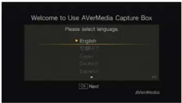
Setting up Language
When the welcome page appears, use ▲/▼ to select your preferred language. Press OK to confirm.
text_image
Welcome to Use AVerMedia Capture Box Please select language. English 英语中文 Cesky Deutsch Español OK Next AVerMedia
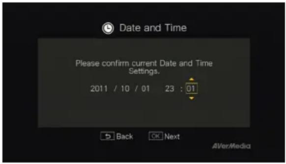
Step 2 Setting up Date and Time
Use ◀/▶ to move among options and ▲/▼ to adjust date and time. Press OK to confirm.
text_image
Date and Time Please confirm current Date and Time Settings. 2011 / 10 / 01 23 : 01 Back OK Next AVer/Media
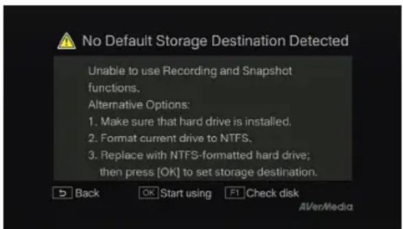
Step 3 (Optional) Installing Storage Device
If you have not yet installed any storage device, install it before continuing the setup process.
BACK
Then press ↩ to go to the previous screen and press OK to run disk checking process.
If you have already installed your storage device beforehand, jump to Step 5.
text_image
No Default Storage Destination Detected Unable to use Recording and Snapshot functions. Alternative Options: 1. Make sure that hard drive is installed. 2. Format current drive to NTFS. 3. Replace with NTFS-formatted hard drive; then press [OK] to set storage destination. Back OK Start using F1 Check disk AVer/Media
- Unplug Game Capture HD from the power supply before installing an internal HDD.
- If your hard drive cannot be detected, refer to FAQ at www.avermedia.com for further troubleshooting.

Step 4 (Optional) Formatting Storage Device
If you are using a new hard drive, a disk format request will be prompted.
Press OK to start the disk format process. Once finished, press OK to start using Game Capture HD.

- Disk formatting will remove all the data stored on the disk. Please properly backup your data before formatting the disk.
- NEVER power off the device or unplug the power supply during the disk format process.

Step 5 Setting up Storage Destination
Use ▲/▼ to select desired default storage disk for both recorded files and snapshots. Press OK to select a disk.

indicates normal write speed of selected partition;

indicates low write speed of selected partition. To make sure recording functions properly, be sure to select partition with normal write speed. If you would like to select partition with ⚠️, please format the partition into NTFS. If the problem persists, refer to FAQ at www.avermedia.com for further troubleshooting.
Then use ▲/▼ to select a folder and press OK to enter.
Press F1 to save setting.

text_image
Select Storage Disk Select disk for recordings and snapshots. USB Disk Partition1 Back OK Enter REC functions properly REC error may occur AVer/Media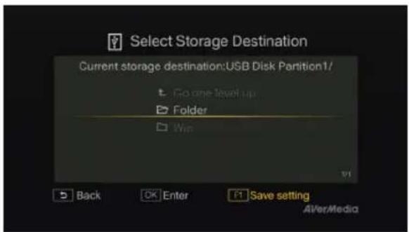
text_image
Select Storage Destination Current storage destination:USB Disk Partition1/ Go one level up Folder Win Back OK Enter F1 Save setting AVer/Media
Step 6 Finishing Setup Wizard
Press OK to exit the wizard and start using Game Capture HD. The game screen then appears.

text_image
Settings Completed Current storage destination:Local HDD Partition2/ AVerMedia Capture Box is ready to use. Main Operations: Open/close menu Start/stop recording Snapshot Back Start using AVerMedia3.4 Supported Resolutions
The Game Capture HD supports Component (YPbPr) input resolution:
| Component (YPbPr) |
| 480i/576i |
| 480p/576p |
| 720p (50 & 60Hz) |
| 1080i (50 & 60Hz) |
3.5 Video Output Settings for Game Consoles
The Game Capture HD supports YPbPr input resolution up to 1080i. If you were using HDMI connection for your game console, you need to set the console's video output to 1080i or below.
3.5.1 Video Output Settings for PS3

- Before resetting video output for PS3, make sure to properly connect Game Capture HD with your PS3.
- Leave both the HDMI cable and Universal Component Cable for Game Consoles (or your console specific component cable) plugged in.
● Make sure to power off both the Game Capture HD and your PS3 beforehand. - Supported resolutions vary depending on the TV in use. For details, please refer to the documentation that comes with your TV.
Step 1
Power on your PS3 console.
On your console, go to Settings > Display Settings > Video Output Settings.
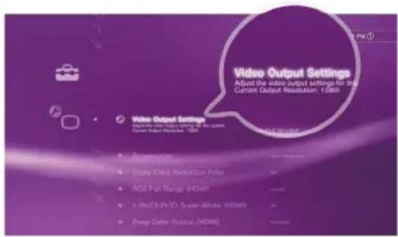
text_image
Video Output Settings Adjust the video output settings for the Current Output Resolution: 1000 Video Output Settings Select the video output settings for the Current Output Resolution: 1000 • SmartBox • iOS Color Production Fuller • RGB Plus Range (HDMI) • i-Photo/Video Split-Window (HDMI) • Drop Color Output (HDMI)
Step 2
Select Component/D-terminal and confirm the selection. Then your TV screen goes blank immediately.
Now use your TV remote to switch the TV input source to Component (YPbPr). The screen then comes back on again.
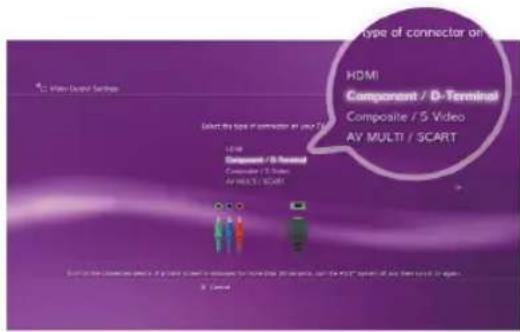
text_image
Type of connector on HDMI Component / D-Terminal Composite / 5 Video AV MULTI / SCART Select the type of connector on your TV LEVE Component / D-Terminal Composite / 5 Video AV MULTI / SCART
Step 3
Check ALL the resolutions except for 1080p.
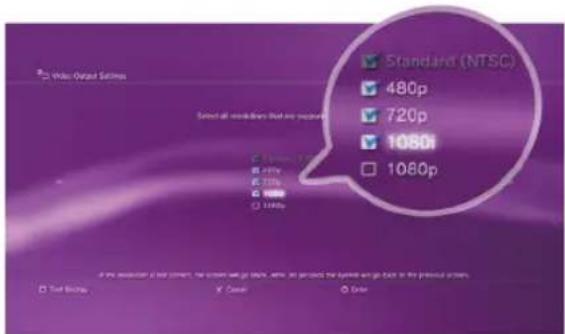
text_image
Standard (NTSC) 480p 720p 1080p 1080p Select all resolutions that are performed □ Normal 100% □ High 100% □ Low 100% □ Medium 100% □ High 100% if the audiolet of our screen, the screen will go back, then, so provided the system will go back in the previous screen. □ Test Rating X Center Enter
Step 4
Confirm the setting.
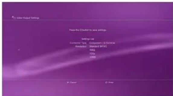
text_image
R25 Video Output Settings Press the OButton to save settings. Settings List Connector Type: Component / [Rathene] Acceleration: Standard NTSC 40Hz F25G 10000 X Cancel Y SaveStep 5
Select Set Audio Output Settings.

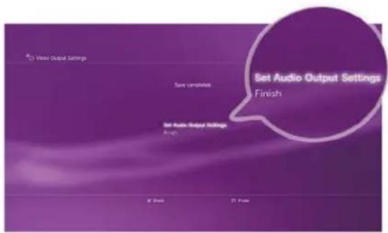
text_image
Set Audio Output Settings Finish Save Utilities Set Audio Output Settings Finish OK Finish Cancel Finish
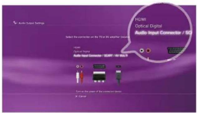
Step 6
Select Audio Input Connector/SCART/AV MULTI as audio output.
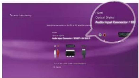
text_image
HDMI Optical Digital Audio Input Connector / SOD Select the connector on the PV or W monitor to secure HDMI Optical Digital Audio Input Connector / SCART / AV SOLID Turn at the power of the commercial device W Cancer
Step 7
Confirm the setting.
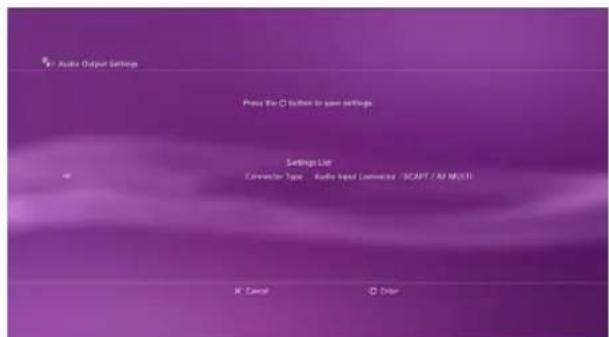
text_image
Audio Output Settings Press the C button to save settings. Settings List Connector Type Audio Input Connector /SCAPT /XP MULT K Cancel D Order3.5.2 Video Output Settings for Xbox 360

- Before resetting video output for Xbox, make sure to properly connect the Game Capture HD with your Xbox.
- Make sure to remove the HDMI cable beforehand, if it was plugged in.
- Make sure to power off both the Game Capture HD and your Xbox beforehand.
- Supported resolutions vary depending on the TV in use. For details, please refer to the documentation that comes with your TV.
Step 1
Power on your Xbox console.
On your console, go to My Xbox on the dashboard and scroll all the way to the right to System Settings.
Then select Console Settings > Display > HDTV Settings.
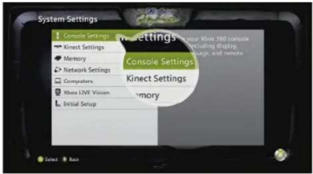
text_image
System Settings ! Console Settings Kinect Settings ● Kinect Settings ● Memory ● Network Settings □ Computers ○ Xbox LIVE Vision L Initial Setup Kinect Settings ● your Xbox 380 console including display, image, and remote ● Memory
Step 2
Adjust the output setting to 1080i or below from the menu list. Select Yes to confirm the setting.
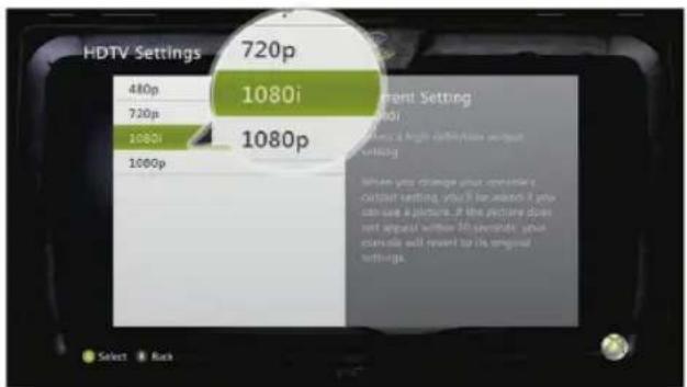
text_image
HDTV Settings 480p 720p 1080i 1000p 720p 1080i 1080p Current Setting Current Setting Where you change your original output setting, you will be asked if you can use a picture. If the portfolio does not appear within the controls, you console will revert to its original settings. Select Rock
For more information concerning console's video output settings, please refer to the setup instruction that comes with your game console.
Chapter 4 The Remote Control
The descriptions below show the deployment of the keys on the remote control.

- On Real-time Mode, the remote keys are invalid, except for (mode), (start/stop recording),
(stop recording).
(snapshot), and
(power).


- Press

to switch between Standard Mode and Real-time Mode. (See p.26 for details).
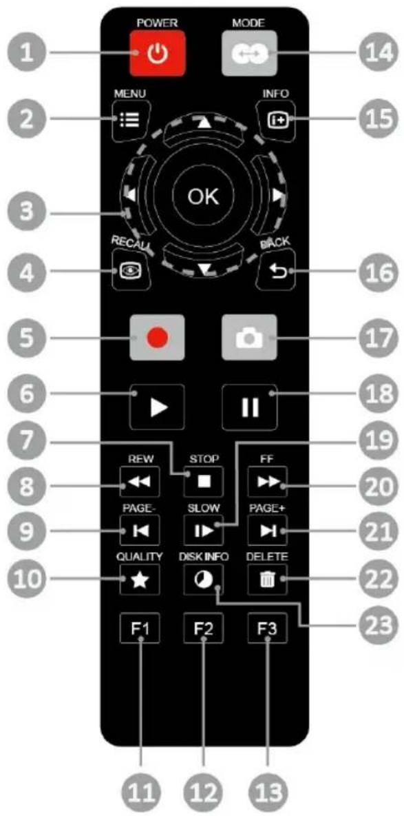
text_image
POWER MODE MENU INFO OK RECAU BACK 14 15 16 17 18 19 20 PAGE- SLOW PAGE+ 21 QUALITY DISK INFO DELETE 22 F1 F2 F3 23 11 12 13English-24
| # Buttons | Descriptions | |
| 1 |  | Press to turn the unit on / into stand-by mode.* Stand-by mode: power-saving sleep mode. |
| 2 |  | Press to access the main menu. Press again to exit. |
| 3 |  | Press the navigation keys to move among options.Press OK to confirm a selection. |
| 4 |  | Press to play the last recorded file or view the last captured image. |
| 5 |  | Press to start / stop recording. |
| 6 |  | Press to start playing the selected file.Press to play the file at normal (1x) speed when slow motion, rewind, or fast-forward is active. |
| 7 |  | Press to stop the playback.Press to stop the recording. |
| 8 |  | Press to rewind (2x, 4x, 8x, 16x, 32x). |
| 9 | PAGE- | Press to return to the previous page. |
| 10 |  | Press to display the video/snapshot quality adjustment screen. Press again to exit. |
| 11 |  | (Follow the on-screen instruction) |
| 12 |  | (Follow the on-screen instruction) |
| 13 |  | (Follow the on-screen instruction) |
| 14 |  | Press to switch between Real-time Mode and Standard Mode during gameplay (See p.26 for details). |
| 15 | [G3S7] | Press to display the on-screen information. |
| 16 |  | Press to exit the current page and return to the previous page. |
| 17 |  | Press to take a snapshot during gameplay or video playback. |
| 18 |  | Press to pause the playback. Press OK or ▶ to resume playback. |
| 19 |  | Press to play the video in slow motion (1/2x). Press again to enter frame-by-frame mode (See p.27 for details). |
| 20 |  | Press to fast-forward (2x, 4x, 8x, 16x, 32x). |
| 21 |  | Press to go to the next page. |
| 22 |  | Press to delete the selected files. |
| 23 |  | Press to display the disk information. Press again to hide it. |
Chapter 5 Gameplay Capture
This chapter guides you to record gameplay, capture images, and instantly play files.
5.1 Live Preview Screen (Standard Mode & Real-time Mode)
Every time you power on the Game Capture HD, Standard Mode is set as default. If you would like to switch to Real-time Mode, press 📊. To switch back to Standard Mode, press 📊 again.
On Standard Mode, you can press MENU to bring up the menu while playing game with unnoticeable 0.1 second of lag.
On Real-time Mode, both the menu and on-screen information are disabled while the gameplay is displayed in real-time. On this mode, only recording and snapshot functions are available.

● Recording and snapshot functions are only available if the storage device is properly installed.
- To change the storage destination, please go to Menu > Settings > Disk Management > Storage Destination (See p.38 for details).
- Recording is real-time on both modes. If there is any lag, refer to FAQ at www.avermedia.com for further troubleshooting.
5.2 Gameplay Capture on Standard Mode
OSD Menu
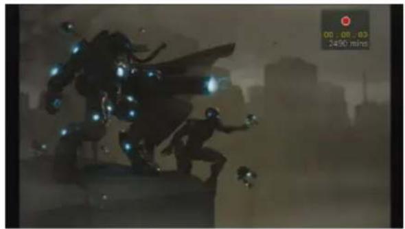
natural_image
Silhouette of a futuristic armored figure with glowing blue lights, set against a cityscape background (no readable text or symbols)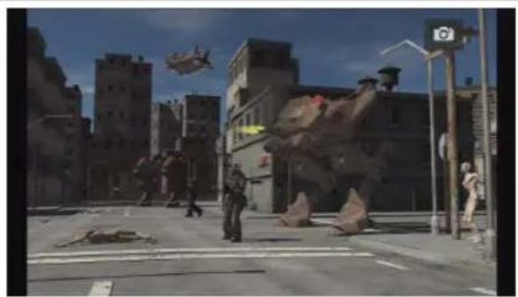
natural_image
Street scene with debris, a helicopter flying overhead, and urban buildings in the background (no visible text or symbols)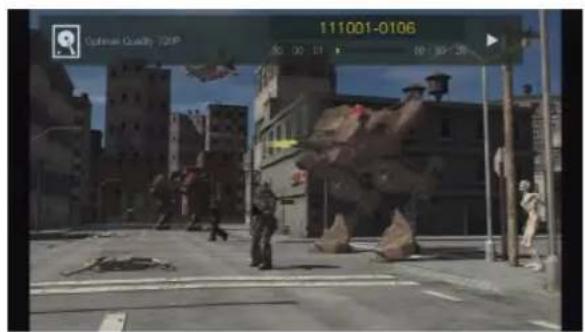
text_image
111001-0106 Optimer Quality 20MP 50 30 17 50:30:28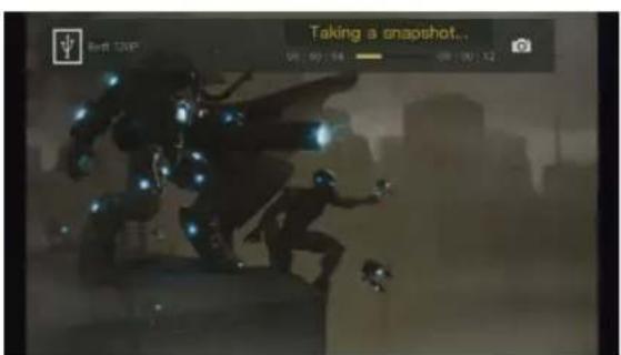
text_image
Taking a snapshot... 00:00:54 00:00:12Descriptions
Instant Recording During Gameplay
- Press to activate instant recording.
- Press ● again or □ to stop recording.
Quick Snapshot During Gameplay
- Press 🔒 to capture current image.
Instant Playback
- Press 📋 to play the last recorded file or view the last captured image.
- Press STOP to stop the playback.
RECALL
Image Capture During Video Playback
Way 1:
- Press 🔒 to capture current image.
Way 2:
Step 1:
- Press ▶ to play the video in slow motion (1/2x). Press ▶ again to view the video frame by frame.
text_image
Video/Snapshot Quality Video Quality Optimal Snapshot Quality Best1 In Back OK Enter AVer/Mediaor
- Press □ to pause the playback. Press ▶ to go to previous frame; press ▶ to go to next frame.
Step 2:
- Press to capture your desired image.
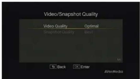
Video / Snapshot Quality Adjustment
Step 1:
Press ★ to display the video/snapshot quality adjustment screen.
Step 2:
Use ▲/▼ to select "Video Quality" or "Snapshot Quality" and press OK.
Step 3:
Use ▲/▼ to select desired option and press OK to confirm.
Step 4:
Press BACK to exit.
text_image
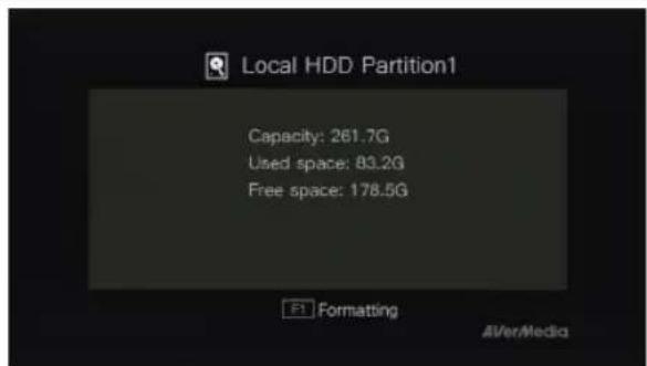
Local HDD Partition1 Capacity: 261.7G Used space: 83.2G Free space: 178.5G F1 Formatting AI/Ver/MediaDisk Information
- Press ☐ to display the disk information. Press again to hide it.
text_image
Menu 01:06 Recordings and Snapshots File Management Settings Close menu AI/VerMediaMain menu
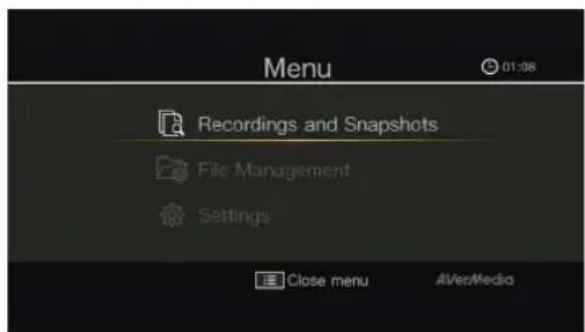
- Press MENU to call up the main menu. - Press MENU or BACK to return to the game screen.
5.3 Gameplay Capture on Real-time Mode
OSD Menu
natural_image
Silhouette of a futuristic armored figure with glowing elements, set against a smoky cityscape background (no text or symbols visible)Descriptions
Instant Recording During Gameplay
- Press ● to activate instant recording
- Press ● again or □ to stop recording.
natural_image
Street scene with debris, a helicopter flying overhead, and urban buildings under a clear blue sky (no visible text or symbols)Quick Snapshot During Gameplay
- Press to capture current image.
Chapter 6 The OSD Menu Display
Under the menu, you can check and manage both your recorded files and snapshots, and customize your preferences.

Under Real-time mode, the OSD menu display is not available. To call up the menu, press to switch
back to Standard Mode and then press

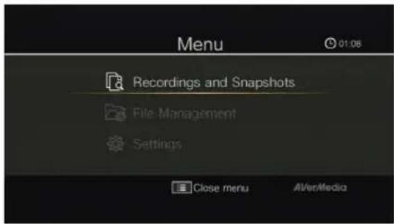
OSD Menu Descriptions
text_image
Menu 01:08 Recordings and Snapshots File Management Settings Close menu AIVer/MediaBasic Operation
MENU
- Press :≡ to bring up the menu.
MENU
BACK
- Press :≡ or ↩ to return to the game screen.
- Use ▲/▼ to make selection on the menu and OK to enter a submenu.
- In the submenu, use ▲/▼ to make selection and OK to confirm. Press BACK to return to the previous page.
6.1 Recordings and Snapshots
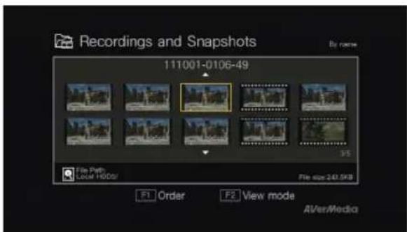
You can check both recordings and snapshots captured by the Game Capture HD in "Recordings and Snapshots".
Capture Format:
Video AVI (Codec: H.264 format with MP3 audio)
Image JPEG

To convert captured videos from AVI to MP4 (Codec: H.264 format with MP3 audio) for editing, please go to http://www.avermedia.com and download "MP4 Converter" from "AP & Driver" section on the product information page.
OSD Menu Descriptions
text_image
Recordings and Snapshots 111001-0106-49 File Path Local H1003/ File size: 241.5KB F1 Order F2 View mode AVer/MediaNavigating
- Use the navigation keys ◀/▶/▲/▼ to select among items.
- Press F1 to sort the files by file name, file size, or file format.
- Press F2 to switch between list mode and thumbnail mode.
- Press 🖼️ to go to the next page.
- Press return to the previous page.
- Press MENU to directly access the main menu.
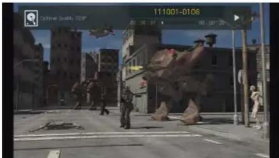
Video Playback
- Press ▶ or OK to start playing the selected video.
- Press ☐ or OK to pause the playback.
Press ▶ or OK to resume playback. - Press ▶ to play the video in slow motion
text_image
111001-0106 00:00 19:30 00:00-20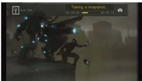
text_image
Taking a snapshot... 00:08:36 00:09:12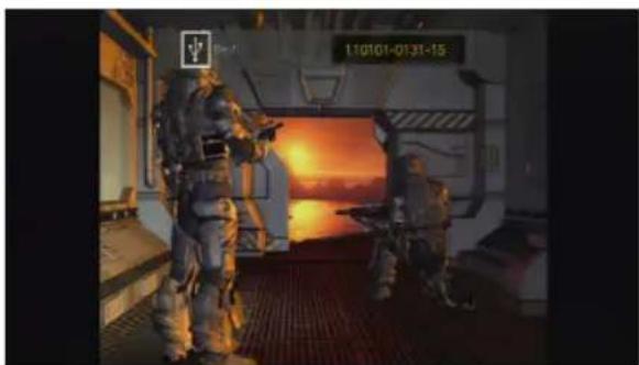
natural_image
Interior view of a spacecraft with crew members observing a sunset sky (no visible text or symbols)(1/2x).
- Press to rewind at 2x, 4x, 8x, 16x, 32x speed.
- Press ▶ to fast forward at 2x, 4x, 8x, 16x, 32x speed.
- Press ▶ to play the file at normal (1x) speed when slow motion, rewind, or fast-forward is active.
- Press □ to stop the playback.
- Press ⓘ to display the playback information, including storage disk, recording resolution, duration, elapsed and remaining time, and file name.
Image Capture During Video Playback
Way 1:
- Press 📄 to pause and capture current image.
- Press ▶ or OK to resume playback.
Way 2:
Step 1:
- Press ▶ to play the video in slow motion (1/2x). Press ▶ again to view the video frame by frame.
or
- Press □ to pause the playback. Press ▶ go to previous frame; press ▶ to go to next frame.
Step 2:
- Press to capture your desired image.
Snapshots Viewing
- Press ▶ or OK to view the selected image.
Press STOP return.
- Press ⓘ to display the image information, including storage disk and file name.
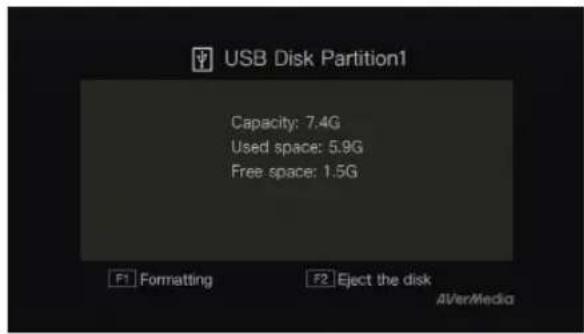
text_image
USB Disk Partition1 Capacity: 7.4G Used space: 5.9G Free space: 1.5G F1 Formatting F2 Eject the disk AI/er/MediaUSB Storage Device Removal
In order to avoid data loss, it is highly recommended to safely remove your external storage device. Please follow the steps below:
Step 1:
Press 📄 on the remote control.
Step 2:
Select the partition.
Step 3:
Press F2 to remove it.
6.2 File Management
"File Management" allows you to manage videos and images captured by the Game Capture HD. You can copy files between internal hard drive and external USB storage device, and delete unwanted files.
Please note that only video and image files captured by the Game Capture HD are supported.
Before entering this submenu, insert your storage device first (USB 2.0 storage device / 2.5" HDD in NTFS format).
File Management User interface:
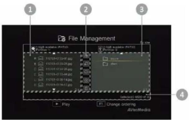
text_image
File Management 1 SGB installed (FAT2) Partition 1 2 SGB installed (FAT3) Partition 2 Play Change ordering A/Ver/Media 41 A list displaying files located on the internal hard disk
2 A set of editing tools
3 A list displaying files located on the USB disk
4 Information display area
Descriptions on Editing Tools:
| # Buttons | Descriptions | |
| 1 |  | Copy files to USB disk |
| 2 |  | Copy files to internal hard disk |
| 3 |  | Select all |
| 4 |  | Deselect all |
| 5 |  | Delete |
OSD Menu Descriptions
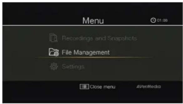
text_image
Menu 01:06 Recordings and Snapshots File Management Settings Close menu AI/VerMedia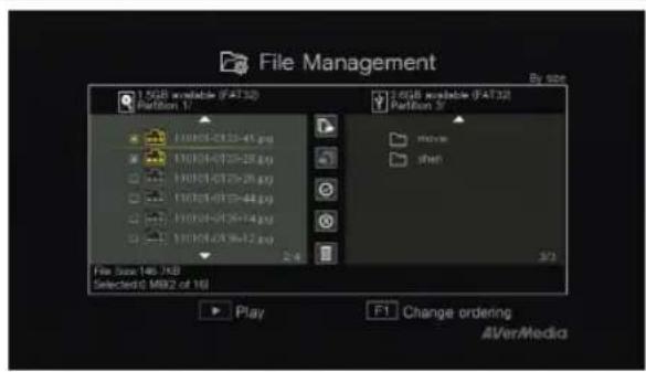
text_image
File Management 1.5GB available (FAT32) Partition 17 11/03/01-01:30-41.jpg 11/03/01-01:30-28.jpg 11/03/01-01:30-26.jpg 11/03/01-01:30-44.jpg 11/03/01-01:30-14.jpg 11/03/01-01:30-12.jpg 2.4 File Size: 146.7GB Selected: 5 MB (2 or 16) Play F1 Change ordering AirVer/MediaNavigating
- Use ▲/▼ to select and OK to enter the folder in which you save the recordings and snapshots.
- Use ▲/▼ to select "Back" and press OK to go one level up.
- Press F1 to sort the files by file name, file size, or file type.
- Press PAGE+ to go to the next page.
- Press return to the previous page.
- Press MENU ≡ to directly access the main menu.
Copying Files from Internal HDD to USB Disk
Step 1:
- On the left-side list, use ▲/▼ to highlight the file that you want to copy to USB disk. Press OK to select / unselect an item.
- Select √ and press OK to select all files.

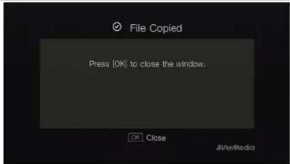
text_image
File Copied Press [OK] to close the window. OK Close AVerMedia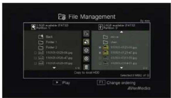
text_image
File Management 1.5GB available (FAT32) Partition 1 1.5GB available (FAT32) Partition 3 Back Folder 1 Folder 2 11/01-0125-06.jpg 11/01-0125-47.jpg 11/01-0125-09.jpg 1/4 Copy to local HDD Selected: U MBU of U Play F1 Change ordering AlVer/Media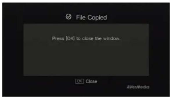
text_image
File Copied Press [OK] to close the window. OK Close AVerMedia- Select ✗ and press OK to deselect all files.
Step 2:
- Select 📄 and press OK to copy selected file(s) to USB disk.
- Press BACK to cancel copying the files in a progress.
Step 3:
- Press OK.
Copying Files from USB Disk to Internal HDD
Step 1:
- On the right-side list, use ▲/▼ to highlight the file that you want to copy to internal HDD. Press OK to select / unselect an item.
- Select √ and press OK to select all files. - Select ✗ and press OK to deselect all files.
Step 2:
- Select 📋 and press OK to copy selected file(s) to internal HDD.
- Press BACK to cancel copying the files in a progress.
Step 3:
- Press OK.
text_image
File Management 1.5GB available (FAT32) Partition 1 110101-0125-06.jpg 110101-0125-07.jpg 110101-0125-08.jpg 1/4 Delete 2.5GB available (FAT32) Partition 3 110101-0125-06.jpg 110101-0125-07.jpg 110101-0125-08.jpg Selected:0 MBQ of 9 Play F1 Change ordering AVer/Medico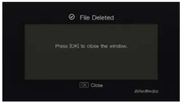
text_image
File Deleted Press [OK] to close the window. Close AVerMedia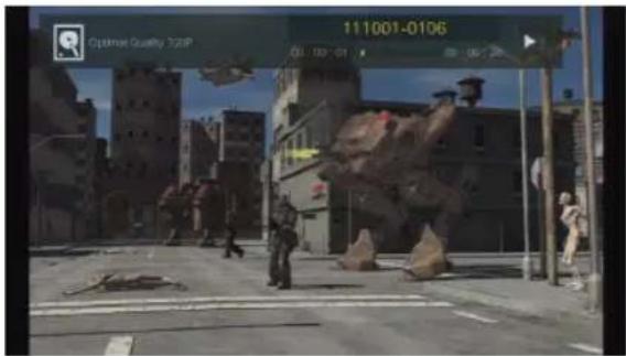
text_image
Optimal Quality 325P 111001-0106 03:00:01 16:24Deleting Files
Step 1:
- Use ▲/▼ to highlight the file(s) that you want to delete. Press OK to select/unselect an item.
- Select √ and press OK to select all files.
- Select ✗ and press OK to deselect all files.
Step 2:
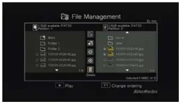
- Select 📋 and press OK to remove the file from the list.
or
Press 📄 on the remote and then press OK to remove the file from the list.
BACK
- Press ↩ to cancel deleting the files in a progress.
Step 3:
- Press OK.
File Playback
- Press ▶ or OK to start playing the highlighted file.
- Press ☐ or OK to pause the playback.
Press ▶ or OK to resume playback.
- Press ▶ to play the video in slow motion (1/2x).
- Press to rewind at 2x, 4x, 8x, 16x, 32x speed.
- Press ➤ to fast forward at 2x, 4x, 8x, 16x, 32x speed.
- Press ▶ to play the file at normal (1x) speed when slow motion/rewind/fast-forward is active.
- Press □ to stop the playback.
- Press i+ to display the playback
text_image
USB Disk Partition1 Capacity: 7.4G Used space: 5.9G Free space: 1.5G F1 Formatting F2 Eject the disk A/Ver/Mediainformation, including storage disk, recording resolution, duration, elapsed and remaining time, and file name.
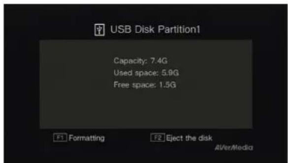
USB Storage Device Removal
In order to avoid data loss, it is highly recommended to safely remove your external storage device. Please follow the steps below:
Step 1:

Press
on the remote control.
Step 2:
Press F2 to remove it.

A single file size that exceeds 4GB is not allowed to be copied from NTFS-formatted HDD to FAT32-formatted USB storage device. To solve this problem, please format your USB storage device to NTFS file system or use a NTFS formatted USB storage device.
6.3 Settings
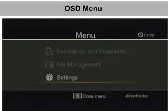
You can customize your preferences in "Settings".
text_image
OSD Menu Menu 01:08 Recordings and Snapshots File Management Settings Close menu AVerMediaDescriptions
Basic Operation
- Use ▲/▼ to select a preferred category. Press OK to make a selection.
- Press ↩ to return to the previous page.
Press MENU to directly access the main menu.
text_image
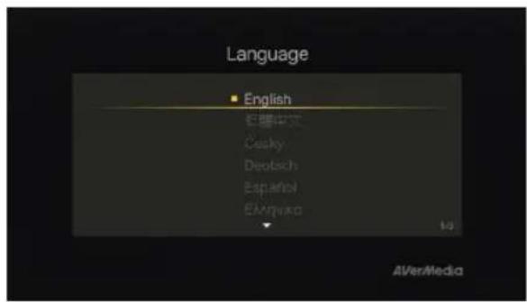
Language English 红雁中文 Cocky Deutsch Español Espanado AVerMediaLanguage
Use ▲/▼ to select your preferred language. Press OK to confirm.
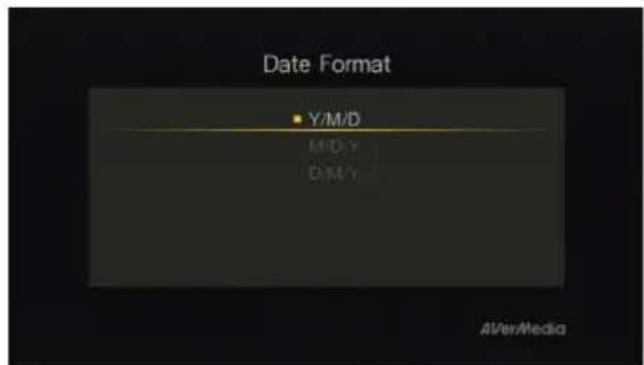
text_image
Date Format Y/M/D M/D/Y D/M/Y AI/VerMedia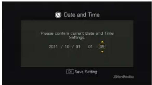
text_image
Date and Time Please confirm current Date and Time Settings. 2011 / 10 / 01 01 : 09 OK Save Setting AVerMedia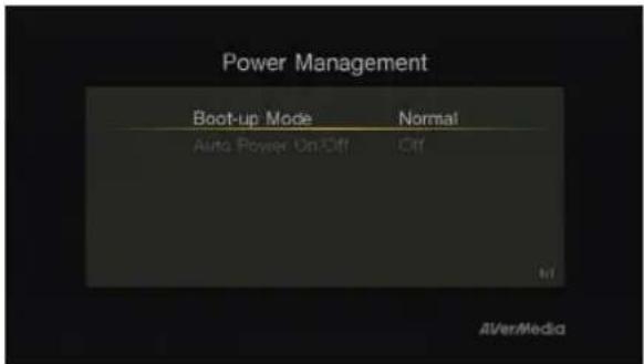
text_image
Power Management Boot-up Mode Normal Auto Power On-Off Off AVerMedia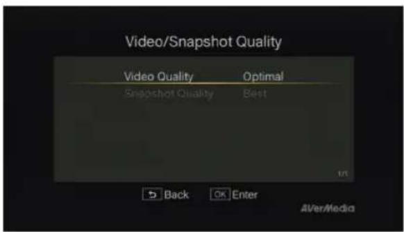
text_image
Video/Snapshot Quality Video Quality Optimal Snapshot Quality Best Back OK Enter Aver/MediaDate Format
Use ▲/▼ to select date format. Press OK to confirm.
Date and Time
Use ◀/▶ to move among options and ▲/▼ to adjust date and time. Press OK to confirm.
Power Management
Boot-up Mode
Use ▲/▼ to switch between different boot-up modes (Normal/Fast). Press OK to confirm.
*Fast Mode speeds up the boot time, though more electricity is consumed.
Auto Power On/Off
Use ▲/▼ to set the device to auto-power on or off. Press OK to confirm.
* Auto-power off: the device auto powers off when the signal input is unavailable for 10 minutes. The device auto powers on when the signal input is back on.
Video/Snapshot Quality
Video Quality:
Use ▲/▼ to toggle among various video quality options (Optimal/Good/Maximum recording length). Press OK to confirm.
Snapshot Quality
Use ▲/▼ to toggle among various snapshot quality options (Best/Better/Good). Press OK to confirm.
Estimated recording duration for different video quality settings:
HD (1080i)
| Storage Capacity\Video Quality | Optimal(15 Mbps) | Good(12 Mbps) | Maximum RecordingLength (10 Mbps) |
| 1TB 125 hrs 150 hrs 200 hrs | |||
| 2TB 250 hrs 300 hrs 400 hrs |
HD (720p)
| Storage Capacity\Video Quality | Optimal(12 Mbps) | Good(10 Mbps) | Maximum RecordingLength (8 Mbps) |
| 1TB 150 hrs 200 hrs 250 hrs | |||
| 2TB 300 hrs 400 hrs 500 hrs |
SD 480i(576i)/480P(576P)
| Storage Capacity\Video Quality | Optimal(7.5 Mbps) | Good(5 Mbps) | Maximum RecordingLength (3 Mbps) |
| 1TB 250 hrs 400 hrs 650 hrs | |||
| 2TB 500 hrs 800 hrs 1300 hrs |
*Recordings with higher video quality take up more disk space.
text_image
Select Storage Disk Select disk for recordings and snapshots. USB Disk Partition1 Back OK Enter REC functions properly REC error may occur Alver/MediaDisk Management
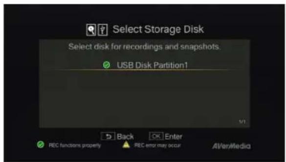
Storage Destination
Step 1:
Use ▲/▼ to select desired default storage disk for both recorded files and snapshots. Press OK to select a disk.
* indicates normal write speed of selected partition;
△ indicates low write speed of selected partition. To
make sure recording functions properly, be sure to select partition with normal write speed.
text_image
Select Storage Destination Current storage destination:USB Disk Partition1/ Go one level up Folder Win Back OK Enter F1 Save setting AVer/Media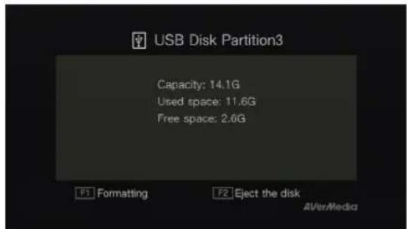
text_image
USB Disk Partition3 Capacity: 14.1G Used space: 11.6G Free space: 2.6G F1 Formatting F2 Eject the disk A/Ver/Media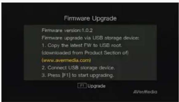
text_image
Firmware Upgrade Firmware version:1.0.2 Firmware upgrade via USB storage device: 1. Copy the latest FW to USB root. (downloaded from Product Section of) (www.avermedia.com) 2. Connect USB storage device. 3. Press [F1] to start upgrading. F1 Upgrade AVerMediaStep 2:
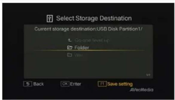
Use ▲/▼ to select a folder and press OK to confirm.
Step 3:
Press F1 to save the setting.
Disk Information
This page displays the status of storage capacity of the disk.
Press F1 to start formatting the disk.
Press F2 to eject the disk.
Firmware Upgrade
Follow the steps below to upgrade the firmware via USB storage device:
Step 1:
To download the latest firmware binary package, please go to www.avermedia.com, and then enter the model name in Product Search field. Firmware file is available on the product information page.
Step 2:
Extract the files by unzipping the package. Copy the firmware files to the root directory of your USB storage device, and then connect it to the Game Capture HD.
Step 3:
Press F1 to start the firmware upgrade
BACK
process. Press ↩ to abort the operation and return to the previous page.
Step 4:
The Game Capture HD automatically detects whether a newer version of firmware is available for upgrade. Once the firmware
upgrade process has completed, press OK to restart the Game Capture HD.

- The firmware upgrade process takes up approximately 3-5 minutes.
- Firmware upgrade requires at least 256MB free space of the storage device (USB/HDD).
- If problems encountered during firmware upgrade, please clear all the data stored on your USB storage device and repeat the process above.
- NEVER power off the device or unplug the power supply during the firmware upgrade process. If the firmware upgrade is interrupted for any reason, the device may crash.

text_image
Restore to Factory Default This will restore AVerMedia Capture Box to the default factory settings. Press [F1] to start restoring. Once the restore process has completed, the device will restart and run Setup Wizard.Restore to Factory Settings
Press F1 to restore to original factory settings. Press BACK → to abort the operation and return to the previous page.
text_image
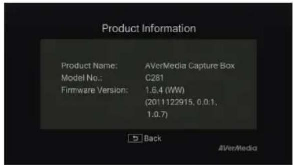
Product Information Product Name: AVerMedia Capture Box Model No.: C281 Firmware Version: 1.6.4 (WW) (2011122915, 0.0.1, 1.0.7) Back AVerMediaProduct Information
This page provides information about this product, including product name, model no., and firmware version.
Appendix A How to Set Your Gameplay Snapshot as PS3 Wallpaper
Start to give your PS3 menu screen a fresh and personalized look to show how cool you are! Please follow the steps below to set the image captured by the Game Capture HD as your PS3 background wallpaper.
Step 1
Remove your USB storage device from the Game Capture HD, and then plug it into your PS3 console via USB port. Power on your PS3 console.

Step 2
On your console, go to Photo > USB Device.
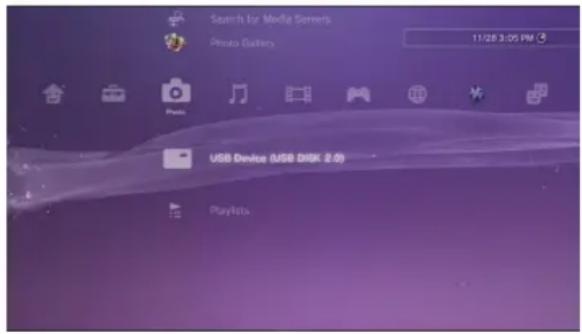
text_image
Search for Media Servers Photo Gallery 11/28 3:05 PM PS USB Device (USB DRK 2.0) Playlists
Step 3
Press the triangle button on your PS3 controller and select "Display All".
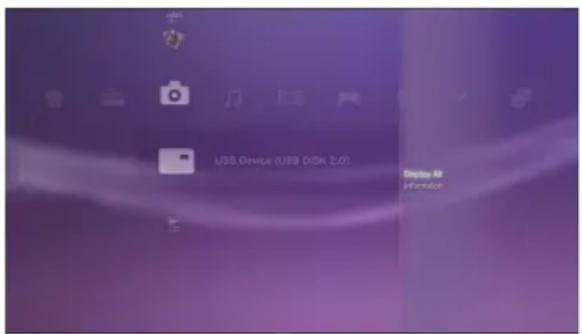
text_image
USB Device (USB Disk, 2.0) Display All Information
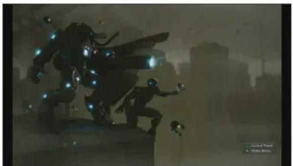
Step 4
Select the image that you wish to use.
natural_image
Illustration of a futuristic character with glowing blue spheres and dynamic pose, set against a cityscape background (no text or symbols)
Step 5
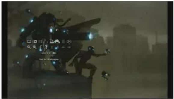
Press the Triangle button on your PS3 controller to bring up control panel.
Then scroll to the right and select "Set as Wallpaper".
natural_image
Silhouette of a futuristic robot-like figure in motion against a city skyline, with no visible text or symbols.
Step 6
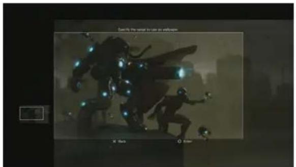
Use the right joystick to zoom in/out and left joystick to frame the image. When it is the proper size, press○ (Enter).
Confirm with ○ (Enter) if you are prompted to overwrite your current wallpaper.
natural_image
Illustration of a dynamic action scene with glowing elements and floating objects (no text or symbols)
Step 7
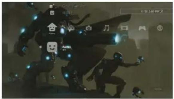
Done! The snapshot that you have chosen is now set as your PS3 wallpaper.
text_image
Street photo with visible store signboards and digital interface elements
On your PS3 console, you can go to Settings > Theme Settings > Background to turn wallpaper on or off.
目錄
第一章 包装配件 2
第二章 產品概觀 .... 4
natural_image
Simple line drawing of a mechanical component with a spring and shaft (no text or symbols)電源變壓器 (12V/1.5A)
natural_image
Simple line drawing of a mechanical bracket or clamp (no text or symbols)電源變壓插頭
natural_image
Pure diagram of two identical USB connectors connected in a symmetric cross pattern (no text or symbols)色差端子連接線
natural_image
Pure electrical circuit lines without any symbolsRCA 音源線
text_image
使用手册使用手册
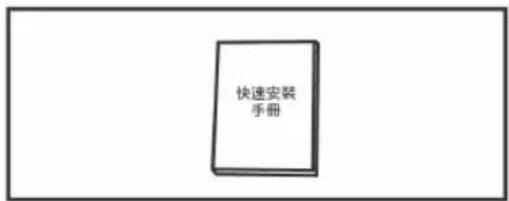
text_image
快速安装 手册快速安装手册
natural_image
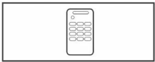
Simple line drawing of a calculator with no text or symbols遙控器(附電池)
natural_image
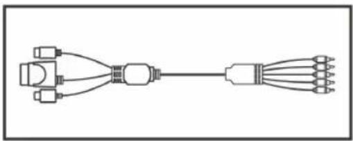
Pure electrical connector diagram without any text, numbers, or symbols遊戲機專用色差端子連接線
flowchart
graph TD
    A["Hand holding battery"] --> B["Switch"]
    B --> C["Motor component with arrow indicating direction"]
    C --> D["Arrow pointing down"]
步驟六
連接至電源
text_image
Diagram showing connection between a remote control device and a power outlet, with a downward arrow indicating signal flow.步驟七
開啟 HD 錄影盒
natural_image
Line drawing of a hand pressing down on an AirMedi device (no text or symbols on the device itself)
步驟二
測量硬碟厚度
natural_image
Hand placing a component into a rectangular device frame (no text or symbols visible)text_image
Diagram illustrating a device's internal processing step with directional arrows and a magnified view of the component.步驟五
蓋回硬碟蓋
natural_image
Illustration of hands assembling a device into a housing with two downward arrows indicating internal components (no text or symbols)繁體中文-16
步驟三
蓋回硬碟蓋
text_image
480p 720p 1080p 1080p繁體中文-21
步驟四
確認設定內容。

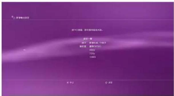
text_image
DAV/DC 大幅(喇叭)包 HDMI 上端 断音输出端子/SCART/AV MULTI HDMI 光源 断音输出端子/SCART/AV MULTI HDMI DC DC DC DC DC DC DC DC DC DC DC DC DC DC DC DC DC DC DC DC DC DC DC DC DC DC DC DC DC DC DC DC DC DC DC DC DC DC DC DC DC DC DC DC DC DC DC DC DC DC D繁體中文-22

步驟七
確認設定內容。
text_image
00:00:02 00:00:15 00:00:15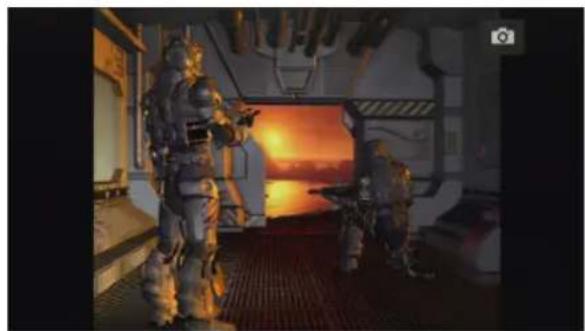
natural_image
Interior of a futuristic sci-fi corridor with two armored figures, one holding a weapon, under a bright sunset sky (no visible text or symbols)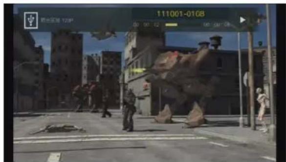
text_image
111001-0108 20 00 02 00 00:00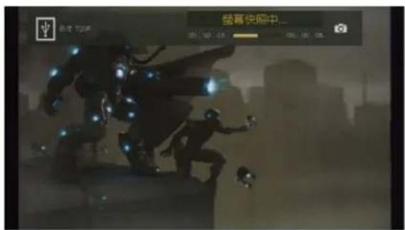
text_image
盛幕快照中...說明
即時錄影
natural_image
Silhouetted figures in dynamic poses against a city skyline, no visible text or symbols
natural_image
Interior of a futuristic spacecraft or industrial facility with two armored personnel operating equipment near a glowing orange screen (no visible text or symbols)說明
即時錄影
- 按 開始錄製影片。
再按一次 ● 或按 □ 停止錄影。
螢幕快照
- 按 進行單張擷圖。
第六章 OSD 選單設定
text_image
111001.0108 00 00:52 00:00:08說明
基本操作
text_image
111001-0114-07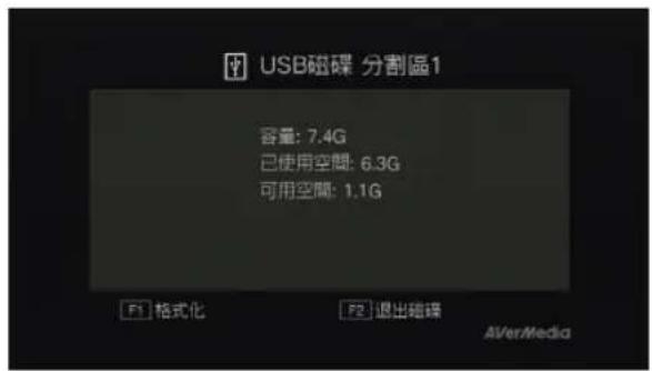
text_image
Terminal 720P Beyond time about minutes步驟二:
natural_image
Silhouette of a futuristic armored figure with glowing blue lights, set against a city skyline (no visible text or symbols)
步驟五
natural_image
Silhouette of a futuristic character with glowing elements against a cityscape background (no readable text or symbols)
步驟六
text_image
Street photo with visible store signboards and a futuristic robot illustration
natural_image
Simple line drawing of a mechanical component with a spring and shaft (no text or symbols)Блок питания
natural_image
Simple line drawing of a mechanical bracket or clamp (no text or symbols)text_image
T Ps/Ct Pt/C COMPONENT HOLD A:0001 00:40natural_image
Line drawing of a remote control unit with ports, cable, and power outlet (no text or symbols)
natural_image
Hand placing a component into a rectangular device frame (no text or symbols visible)Русский-15
text_image
Diagram illustrating a device's internal processing step with directional arrows and a magnified view of the component.text_image
AverMagedWar 2
natural_image
Illustration of hands installing a device into a rectangular frame with two downward arrows indicating internal components (no text or symbols)Русский-17

War 3
text_image
Video Output Settings Adjust the video output settings for the Current Output Resolution, 1080/-
War 2
text_image
Video Parcel Settings Select the types of connector on your TV HDMI Component / D-Terminal Composite / S Video AV MULTI / SCART Type of connector on HDMI Component / D-Terminal Composite / S Video AV MULTI / SCART Two on the connected device. It is more important to designed for more than 50 seconds, then the HMI® system of and type has been again K. Cercio
War 3
text_image
Video Output Settings Select all resolutions that are supported Standard (NTSC) 480p 720p 1080i 1080p If the result plan is not correct, the session will go Share. After 30 seconds the episode will go back to the pressure screen Start Display Next Cancel Show
War 4
text_image
Voice Output Settings Press the Clution to save settings. Settings List Connector Type Component / D-External Resolution Standard (MTSC) 460p 776s 1500s Cancel Enter
War 5
text_image
Set Audio Output Settings Finish Save completed. Set Audio Output Settings Finish X: Back O: Enter
War 6
text_image
To Audio Output Settings Select the connector on the TV or AV together when HDMI Optical Digital Audio Input Connector / SCART / 6V MIA.1 Turn on the power of the connected devices X Canah HDMI Optical Digital Audio Input Connector / SG TOMI SUNO X CanahРусский-24

War 7
text_image
Audio Output Settings Press the CD button to new settings. Settings List Connector Type Audio-Input Connector - SCMT / AV MSCI IC Control CD Modetext_image
System Settings ! Console Settings Kinect Settings Kinect Settings Kinect Settings Kinect Settings Kinect Settings Kinect Settings Kinect Settings Kinect Settings Kinect Settings Kinect Settings Kinect Settings Kinect Settings Kinect Settings Kinect Settings Kinect Settings Kinect Settings Kinect Settings Kinect Settings Kinect Settings Kinect Settings Kinect Settings Kinect Settings Kinect Settings Kinect Settings Kinect Settings Kinact Settings Kinact Settings Kinact Settings Kinact Settings Kinact Settings Kinact Settings Kinact Settings Kinact Settings Kinact Settings Kinact Settings Kinact Settings Kinact Settings Kinact Settings Kinact Settings Kinact Settings Kinact Settings Kinact Settings Kinact Settings Kinact Settings Kinact Settings Kinact Settings Kinact Settings Kinact Settings Kinact Settings Kinact Settings Kinct Settings Kinct Settings Kinct Settings Kinct Settings Kinct Settings Kinct Settings Kinct Settings Kinct Settings Kinct Settings Kinct Settings Kinct Settings Kinct Settings Kinct Settings Kinct Settings Kinct Settings Kinct Settings Kinct Settings Kinct Settings Kinct Settings Kinct Settings Kinct Settings Kinct Settings Kinct Settings Kinct Settings Kinct Settings KinCT Settings KinCT Settings KinCT Settings KinCT Settings KinCT Settings KinCT Settings KinCT Settings KinCT Settings KinCT Settings KinCT Settings KinCT Settings KinCT Settings KinCT Settings KinCT Settings KinCT Settings KinCT Settings KinCT Settings KinCT Settings KinCT Settings KinCT Settings KinCT Settings KinCT Settings KinCT Settings KinCT Settings KinCT Settings KinACT Settings KinACT Settings KinACT Settings KinACT Settings KinACT Settings KinACT Settings KinACT Settings KinACT Settings KinACT Settings KinACT Settings KinACT Settings KinACT Settings KinACT Settings KinACT Settings KinACT Settings KinACT Settings KinACT Settings KinACT Settings KinACT Settings KinACT Settings KinACT Settings KinACT Settings KinACT Settings KinACT Settings KinACT Settings KinCACT Settings KinCACT Settings KinCACT Settings KinCACT Settings KinCACT Settings KinCACT Settings KinCACT Settings KinCACT Settings KinCACT Settings KinCACT Settings KinCACT Settings KinCACT Settings KinCACT Settings KinCACT Settings KinCACT Settings KinCACT Settings KinCACT Settings KinCACT Settings KinCACT Settings KinCACT Settings KinaCIA C150 Console, Modulating display, Language, and Remote
War 2
text_image
HDTV Settings 720p 480p 720p 1080i 1080p Main Setting Main Main: a high, deflation output setting 1080p 0000p 0000p 0000p 0000p Select Back
natural_image
Street scene with two armored figures in a damaged urban environment, one holding a weapon, no visible text or symbolsОписание
Запись видео
natural_image
Street scene with debris, a helicopter flying overhead, and urban buildings in the background (no visible text or symbols)Снимок экрана
natural_image
Silhouette of a futuristic armored figure with dynamic pose, set against a city skyline (no text or symbols visible)Описание
Запись видео
natural_image
Street scene from a war-torn urban environment with soldiers, debris, and damaged buildings under a clear sky (no visible text or symbols)Снимок экрана
natural_image
Two armored personnel in a futuristic, glowing environment with a sunset sky and smokestacks (no visible text or symbols)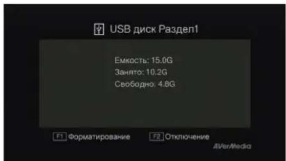
natural_image
Game scene from Oceania: Black Strucky, showing armored characters in a debris-strewn urban environment (no readable text or symbols)
natural_image
Silhouette of a futuristic robot in motion against a city skyline, no visible text or symbols
War 5
natural_image
Silhouette of a futuristic character holding a device, with city skyline in background (no visible text or symbols)
War 6
text_image
Family the range of use as wellcome X: Back O: Save
War 7
text_image
Street photo with visible store signboards and a robot figure surrounded by app icons
natural_image
Simple line drawing of a mechanical component with a spring and shaft (no text or symbols)Netzteil
natural_image
Simple line drawing of a mechanical bracket or clamp (no text or symbols)natural_image
Pure diagram of two identical USB connectors connected in a symmetric cross pattern (no text or symbols)Component-Videokabel
natural_image
Pure electrical circuit lines without any symbolsCinch-Audiokabel
text_image
User ManualBedienungsanleitung
text_image
Quick Guide __________________Quick Installation Leitfaden
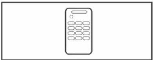
natural_image
Simple line drawing of a calculator with no text or symbolstext_image
Diagram showing connected devices including a speaker, audio jack, and gaming controller with labeled optical components.Schritt 2
text_image
Y Pt/Cb Pt/Cr COMPONENT HESO AUDIO DC: 06 ↓flowchart
graph TD
    A["Device 1"] --> B["Component 2"]
    B --> C["Motor with switch"]
    C --> D["Downward arrow"]
Schritt 6
natural_image
Hand placing a component into a rectangular device frame (no text or symbols visible)Deutsch-15
text_image
Diagram illustrating a device's internal processing step with directional arrows and a magnified view of the component.Schritt 5
natural_image
Illustration of hands installing a device into a rectangular frame with two downward arrows indicating internal components (no text or symbols)Deutsch-17

Schritt 3
text_image
Video Output Settings Adjust the video output settings for this Current Output Resolution: T0500 Video Output Settings Impact the video output settings for this system Current Output Resolution: T0500 Screen cover Cass Color Reduction Filter RGB Fatt Range (HDMI) Y PBS/CE MHz Super-White (HDMI) Deep Color Output (HDMI)Schritt 2
text_image
Video Output Settings Type of connector on HDMI Component / D-Terminal Composite / S Video AV MULTI / SCART Select the type of connector on your TV HDMI Component / D-Terminal Composite / S Video AV MULTI / SCART Turn on the connected device if a touch screen is displayed for more than 30 seconds, turn the PLEP® system off and then turn it off again. X Cancel
Schritt 3
text_image
View Output Settings Select all resolutions that are supported Standard (NTSC) 480p 720p 1080i 1080p If the resolution is not correct, the screen will go back. After 30 seconds the system will go back to the previous screen Next Display Next Cut 8 Box
Schritt 4
text_image
Video Output Settings Press the D button to save settings: Settings List Comparator Type Component / B:\Program\at Respiration Standard (NTC) 4Kcp 72Kp 1300V Cancel Enter
Schritt 5
text_image
Set Audio Output Settings Finish Save completed Set Audio Output Settings Finish X Back O EnterSchritt 6
text_image
Audio Output Settings Select the connector on the TV or AV another in each HDMI Optical Digital Audio Input Connector / SCART / BV MULTIT HDMI Optical Digital Audio Input Connector / SCART / BV MULTIT Turn to the power of E-connection drive X CanonSchritt 7
text_image
Audio Output Settings Press the CD action to other settings. Settings List Connect the Type Audio-Project Connector - SCAPT (AV MULT) X Cancel Videotext_image
System Settings ! Console Settings Kinect Settings Memory Network Settings Computers Xbox LIVE Vision Initial Setup Kinect Settings Console Settings Your Xbox 160 console including display, image, and remote Inventory Initial Setup Select Back
Schritt 2
text_image
HDTV Settings 480p 720p 1080i 1080p 720p 1080i 1080p Current Setting Current Settings 1080i Where you change your console's network setting, you'll be able if you can keep a picture. If the picture does call up within 30 seconds, when console will power up its original settings. Select Back
natural_image
Street scene with armored figures in a war-torn urban environment (no visible text or symbols)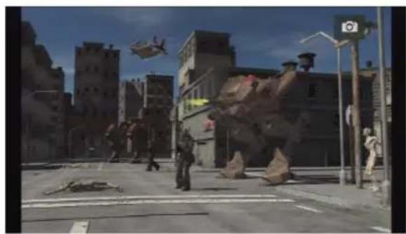
natural_image
Street scene with debris, a helicopter flying, and urban buildings under a clear sky (no visible text or symbols)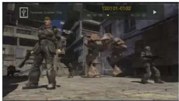
text_image
12/01/01-01/02 Optionale Qualifier /Qtrp 00:00:00 00:00:00Sofortaufnahme
natural_image
Silhouette of a dynamic action scene with glowing elements and distant city skyline (no visible text or symbols)Beschreibung
Sofortige Aufnahme
natural_image
Street scene with debris and modern buildings under a clear sky (no visible text or symbols)natural_image
Monochrome illustration of a futuristic armored figure with glowing blue lights, set against a city skyline (no text or symbols visible)Videowiedergabe
natural_image
Game scene with armored personnel in a city street, no visible text or symbols on the main subjects
text_image
Optimize Counter 20% 12/01/01-01/02 06:00:05 00:04:35Dateien löschen
Schritt 1:
text_image
iUSB Device (508, 2.0) Photo # Please
Schritt 4
natural_image
Silhouette of a futuristic robot-like figure in a cityscape with buildings in the background (no visible text or symbols)
Schritt 5
natural_image
Silhouette of a futuristic robot-like figure with glowing elements, set against a cityscape background (no visible text or symbols)
Schritt 6
text_image
Sperry the game is set to explore A Book C Cover
Schritt 7
text_image
Street photo with visible store signboards and digital interface elements
natural_image
Simple line drawing of a mechanical component with a spring and shaft (no text or symbols)natural_image
Simple line drawing of a mechanical bracket or clamp (no text or symbols)natural_image
Pure diagram of two identical USB connectors connected in a symmetric cross pattern (no text or symbols)natural_image
Pure electrical circuit lines without any symbolsCable de audio RCA
text_image
User ManualManual del usuario
text_image
Quick GuideGuía rápida
natural_image
Simple line drawing of a calculator with no text or symbolsnatural_image
Line drawing of a hand pressing down on an electronic device labeled 'AverMedia' with control buttons (no text beyond label)Paso 2
text_image
9.5 12.5 9.5 12.5natural_image
Hand placing a component into a rectangular housing (no text or symbols visible)Español-15
natural_image
Illustration of hands installing a device component with an inset showing the close-up of the top panel (no text or symbols present)natural_image
Line drawing of a hand pressing down on a device labeled 'AverMedi' with control buttons (no text beyond label)Paso 2
natural_image
Illustration of hands holding a device panel with two downward arrows indicating internal components (no text or symbols)Español-17

Paso 3
text_image
Video Output Settings Adjust the video output settings for the Current Output Resolution: 10901 Video Output Settings Select video output settings for the system Current Output Resolution: 10901 • Recognition • Online Color: Restraction Filter • RGB Full Range (HDMI) • Y Ph/Cy Ph/Cr Super-White (HDMI) • Deep Color Output (HDMI)
Paso 2
text_image
Video Output Settings Select the type of connector on your TV HDMI Component / D-Terminal Composite / S Video AV MULTI / SCART HDMI Component / D-Terminal Composite / S Video AV MULTI / SCART How to be connected device if a card screen is replaced by December 30 seconds, such as the DVD system will be the next 12 seconds. X: CutoffEspañol-22

Paso 3
text_image
Video Output Settings Select of resolutions that are supported Standard (NTSC) 480p 720p 1080i 1080p If the resolution is not correct, the screen will go blank. After 30 seconds the system will go back to the previous screen. Test Display X: Canon Y: Sony
Paso 4
text_image
Inter-Output Settings Press the Outlet to save settings. Settings List Connector Type Component / D-Terminal Respiration Standard (MTEC) 4Kcp 725c 10000 Cancel Enter
Paso 5
text_image
Set Audio Output Settings Finish Save complement Set Audio Output Settings Finish × Back ○ Enter
Paso 6
Seleccione Audio Input Connector(Conector de entrada de audio)/SCART (EUROCONECTOR)/AV MULTI (AV MÚLTIPLE) como salida de audio.
text_image
Audio Output Settings Select the connector on the TV or AV amplifier in vivo HDMI Optical Digital Audio Input Connector / SCAPT / AV Max.0 HDMI Optical Digital Audio Input Connector / SCAPT / AV Max.0 Center the power of the connected devices X : Caneal
Paso 7
text_image
Audio Output Settings Press the CI button to audio settings Settings List Connector Type Audio Input Connector - SCAPT / AV MULT © Cancel © Updatetext_image
System Settings Console Settings Kinect Settings Kinect Settings Kinect Settings Kinet Settings Kinet Settings Kinet Settings Kinet Settings Kinet Settings Kinet Settings Kinet Settings Kinet Settings Kinet Settings Kinet Settings Kinet Settings Kinet Settings Kinet Settings Kinet Settings Kinet Settings Kinet Settings Kinet Settings Kinet Settings Kinet Settings Kinet Settings Kinet Settings Kinet Settings Kinet Settings Kinet Settings Kinet Settings Kinoc 360 console including display, usage, and remote Windows LIVE Vision Initial Setup
Paso 2
natural_image
Street scene with armored personnel and a large dinosaur in urban debris (no visible text or symbols)Descripción
natural_image
Street scene with debris, a helicopter, and urban buildings under a clear sky (no visible text or symbols)natural_image
Silhouette of two armored figures in dynamic poses against a city skyline (no text or symbols visible)Descripción
natural_image
Street scene with damaged buildings, debris, and a helicopter flying overhead (no visible text or symbols)Instantánea rápida
text_image
120101-0102 00:00:03 00:04:25Descripción
Navegación
natural_image
Game scene from a character in a futuristic urban environment with multiple characters and debris (no readable text or symbols)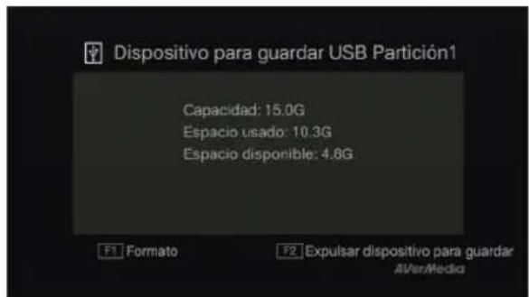
natural_image
Silhouetted character in dynamic pose with glowing elements, set against a city skyline (no text or symbols visible)
Paso 5
natural_image
Illustration of a futuristic robot-like figure in motion against a city skyline, with no visible text or symbols.
Paso 6
text_image
Specify the range of sites as whitepaper X Back D Erwin
Paso 7
text_image
Street photo with visible store signboards and a robot figure in motion, featuring app icons and UI elements.
natural_image
Simple line drawing of a mechanical component with a spring and shaft (no text or symbols)natural_image
Simple line drawing of a mechanical bracket or clamp (no text or symbols)natural_image
Pure diagram of two identical USB connectors connected in a symmetric cross pattern (no text or symbols)natural_image
Pure electrical circuit lines without any symbolsCâble audio RCA
text_image
User Manualnatural_image
Simple line drawing of a calculator with no text or symbolstext_image
Diagram showing connected devices including a device labeled 'OPTICAL' and connected via cable, with a game controller and a console.Étape 2
text_image
Y Pv/Cb Pv/D COMPONENT HOLD AIDS DC/Rtext_image
L-AUDIO COMPONENT HOLD AUDIOnatural_image
Line drawing of two hands holding a small electronic component with no visible text or symbolsnatural_image
Hand placing a component into a rectangular housing (no text or symbols visible)text_image
Diagram illustrating a device's internal processing step with directional arrows and a magnified view of the component.Étape n°5
text_image
AVR-MoDioÉtape n°2
natural_image
Illustration of hands installing a device panel with two downward arrows indicating internal components (no text or symbols)natural_image
Line drawing of a hand pressing a button on an AirMedia device (no text or symbols on the device itself)text_image
Welcome to Use AVerMedia Capture Box Please select language. AVerMedia French OK Next AVerMedia
Étape n°2
text_image
Video Output Settings Adjust the video output settings for the Current Output Revolution: 1000. Video Output Settings Show the video output settings for the system Current Output Revolution: 1000 • Screen Out (I) • Create Color Breakthrough Filter • RGB Full Range (HOM) • V/ PBS/ PBS/ RPE/ Super- White (HOM) • Deep Color Output (HTML)
Étape n°2
text_image
Video Output Settings Select the type of connector on your TV HDMI Component / D-Terminal Composite / S Video AV MULTI / SCART Turn on the connected device. It's Bank screen is displayed for more than 30 seconds, turn the HDMI system off and then turn off again. Cancel
Étape n°3
text_image
Standard (NTSC) 480p 720p 1080l 1080p Select all resolutions that are supposed <30p 250p 1000p 100bp If the resolution is not correct, the screen will go blank. After 30 seconds the cycle will go back in the previous stream. Test Display X Cancer Other
Étape n°4
text_image
Video Output Settings Press for O button to save settings. Settings List Connector Type Component / E-Terminal Resolution Stableant (NTSC) 480p 725p 1000 X Cancel Enter
Étape n°5
text_image
Video Output Settings Save completed. Set Audio Output Settings Finish Set Audio Output Settings Finish Set Audio Output Settings Finish Back Clear
Étape n°6
text_image
Audio Output Settings Select the connector on the TV or AV another device HDMI Optical Digital Audio Input Connector / SCART / AV MULT B Turn at the power of the connected device R. Cervi
Étape n°7
text_image
Audio Output Settings Please the O button to select settings. Settings List Connector Type Audio Input Connector - SCART / AV MLCTI X Cancel O Filtertext_image
System Settings Console Settings Kinect Settings Kinect Settings Kinect Settings Console Settings Kinect Settings Select Back
Étape n°2
text_image
HDTV Settings 480p 720p 1080i 1080p 720p 1080i 1080p Gument Setting 1080i 1080p without your change from the controller's network setting, you'll be bound if you can save a picture if the particle goes out to power addition 30 seconds, your particle will return to its original settings. Select Rock
natural_image
Silhouette of a futuristic armored figure with glowing elements, set against a cityscape background (no readable text or symbols)Description
natural_image
Street scene with a large dinosaur display, debris, and a helicopter flying overhead (no visible text or symbols)natural_image
Silhouette of a futuristic robot and a character in motion, with city skyline in background (no visible text or symbols)Description
natural_image
Street scene with debris and a helicopter flying overhead, no visible text or symbolsAperçu rapide
text_image
12/05/01-01/09 Qualite Opemise Twp 00:00:33 00:00:17ralenti (1/2x).
natural_image
Silhouette of a futuristic robot-like figure in a cityscape with buildings in the background (no visible text or symbols)Étape 5
natural_image
Silhouette of a futuristic robot-like figure in motion against a smoky cityscape background (no visible text or symbols)
Étape 6
text_image
Game scene screenshot showing a robot with multiple UI icons and a timer displaying '15:00 3:00 PM' in the corner.
The following GPL executables and LGPL, MPL libraries used in this product are subject to the BSD/FreeBSD/
GPL/GPLv2/GPLv2+/GPLv3 with GCC/ RLE/jpeg/LGPLv2/LGPLv2.1/LGPLv2.1/ GPLv2/LGPLv2.1+/LGPLv2+/
libpng/MIT/NewBSD/OPENSSL/PD/zlib License Agreements:
BSD
cppstub/db/libpcre0
FreeBSD
thttpd
GPL
madedevs
GPLv2
busybox/dbus/dbus-x11/devmem2/dosfstools/fbset/i2c-tools/iproute2/libblkid1/libdbus-1-3/
libfreetype6/libpam/libuuid1/linux-kernel/module-init-too
ls/module-init-tools-depmod/mtd-utils/
netbase/u-boot/update-modules/usbutils/util-linux-ng
GPLv2+
iptables/sysvinit/tinylogin/udev/update-rc.d
GPLv3 with GCC RLE
libgcc1/libstdc++6
jpeg
libjpeg8/libjpeg-tools
LGPLv2
libts-1.0-0/tslib
LGPLv2.1
libav/libusb-1.0-0
LGPLv2.1/GPLv2
Alsa
LGPLv2.1+
ldd/libc6/libthread-db1
LGPLv2+
libglib-2.0-0
libpng
libpng12-0
MIT
curl/e2fsprogs/fbset-modes/graphmagic/libcom-err2/lib curl4/libe2p2/libexpat1/libext2fs2/libformw/
libmenuw/libpanelw5/libss2/libtic5/libtinfo5/libxml2/ncurses/pointercal
NewBSD
iperf
OPENSSL
openssl
PD
AVerMedia Technologies Inc. offers to provide source code to you for a charge covering the cost of performing such distribution, such as the cost of media, shipping and handling upon e-mail request to AVerMedia Technologies Inc.
at http://www.avermedia.com
For more information, please visit our website:
http://www.avermedia.com/avertv/Product/ProductDetail.aspx?Id=556&tab=UserManual
