iCSPDA2T03 - Flat screen mount Chief - Free user manual and instructions
Find the device manual for free iCSPDA2T03 Chief in PDF.

User questions about iCSPDA2T03 Chief
0 question about this device. Answer the ones you know or ask your own.
Ask a new question about this device
Download the instructions for your Flat screen mount in PDF format for free! Find your manual iCSPDA2T03 - Chief and take your electronic device back in hand. On this page are published all the documents necessary for the use of your device. iCSPDA2T03 by Chief.
USER MANUAL iCSPDA2T03 Chief
Milestone AV Technologies, and its affiliated corporations and subsidiaries (collectively, "Milestone"), intend to make this manual accurate and complete. However, Milestone makes no claim that the information contained herein covers all details, conditions or variations, nor does it provide for every possible contingency in connection with the installation or use of this product. The information contained in this document is subject to change without notice or obligation of any kind. Milestone makes no representation of warranty, expressed or implied, regarding the information contained herein. Milestone assumes no responsibility for accuracy, completeness or sufficiency of the information contained in this document.
Chief® is a registered trademark of Milestone AV Technologies. All rights reserved.

IMPORTANT WARNINGS AND CAUTIONS!
WARNING: A WARNING alerts you to the possibility of serious injury or death if you do not follow the instructions.

CAUTION: A CAUTION alerts you to the possibility of damage or destruction of equipment if you do not follow the corresponding instructions.

WARNING: Failure to read, thoroughly understand, and follow all instructions can result in serious personal injury, damage to equipment, or voiding of factory warranty! It is the installer's responsibility to make sure all components are properly assembled and installed using the instructions provided.

WARNING: Failure to provide adequate structural strength for this component can result in serious personal injury or damage to equipment! It is the installer's responsibility to make sure the structure to which this component is attached can support five times the combined weight of all equipment. Reinforce the structure as required before installing the component.

WARNING: Exceeding the weight capacity can result in serious personal injury or damage to equipment! It is the installer's responsibility to make sure the combined weight of all components attached to the iCSPDA2 does not exceed 40 lbs (18kg).

AVISOS Y PRECAUCIONES IMPORANTES!

Installation Instructions

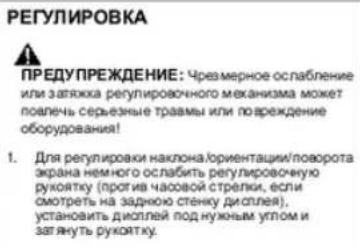
PNEOCTEPEKHEI. PNEOCTEPEKHEI npBQoTtA TOBHOCTBaB X BO3MOXHOCTn NOepeKdHnn nna paspyenHnOBOpDyBaHn,ecn Bn He cnePyTe 3a COOTBeCT ayuoumm HmNc TpydUk

PNDYPTPEKDEHNE. OK3A3HHTATB, YTO6I NOHOCtBIOHOHTB, N C1E20B3T 3A BCEMA WHCTPYKMMM MOKETNPABTEC KOB PEXHOMY TEECHOMY NOPAEKDEHNO. NOPEKDAHEOBOOPDQBAHIN, IIM OCBOSOKEHNO. DAPBOHNHO RAPAHNTI 3TO-OTBECTBENHOCTMOANTXAKHO YPOCTEBPIBTCB, YTO BOE KOMONHENTI DOJIKHM IOBpAO30O6PAHNI YCTAHBMMA IMNCHOBAHINE. NPDEOCTAEHNNHX HINTCPYKNI.

PNDYPTPEKDEHNE. OTKa3 oecenehaB aekbaHTyO CTpykTyO cHbI 3T0o KOmIOHENTA MOKT pNBECTX KOBEPbHO TYENCHOMY NOBpEeHHNO HNOBpETBa HbOOCpyBAHNE! 3TO -OTBCTBHeHCOHTc MOKTHaONKa YQDOCTeepnTc CTpykTyK, K KOTOPR pNOnKeH 3T0 KOmIOHENT,MOKET NODepeKATb NtB pA3 oBcEbnHbB BAc acTe 6OcPOBaAHN. Xypenite CTpyKyy KaK TpeSyTErpeN MOKT AOKOMIOHOM

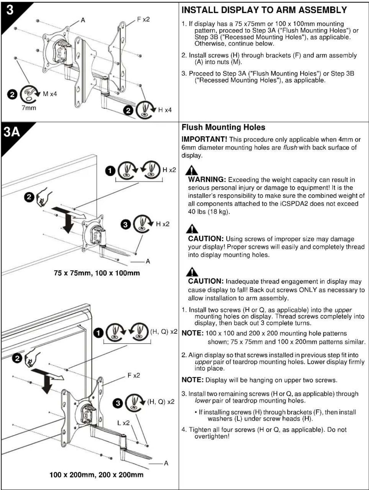
IMPORTANT! If installing a display with recessed mounting holes, then proceed to "INSTALL DISPLAY TO ARM ASSEMBLY" before installing arm assembly to wall plate.
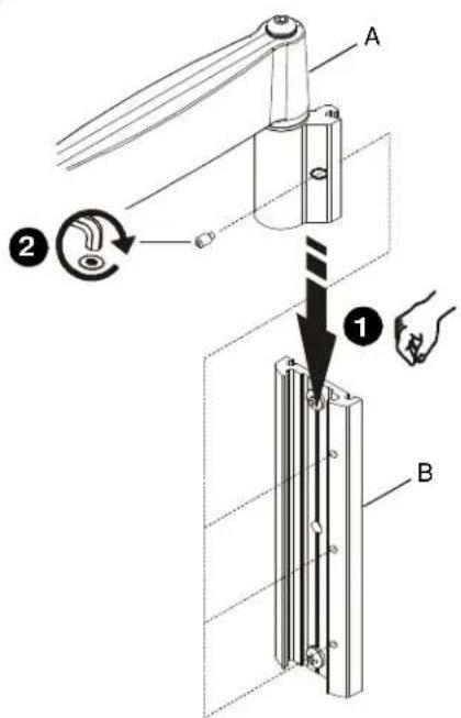
- Align arm assembly (A) with wall plate (B) and slide into position.
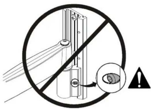
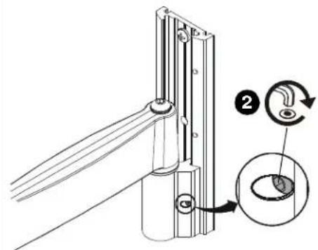
WARNING: Failure to align hex head screw with hole in wall plate (B) may allow arm assembly (A) to fall, resulting in serious personal injury or damage to equipment! Hex head screw should fully recede into arm assembly hole after tightening. - Using hex key (T), tighten hex head screw in arm assembly (A) ensuring that screw engages one of three holes in wall plate (B).
NOTE: Three holes are provided in wall plate (B) to provide height adjustment.
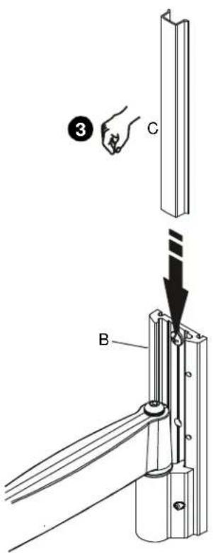
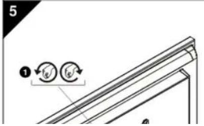
- Align cover (C) with grooves in wall plate (B) and slide into position.
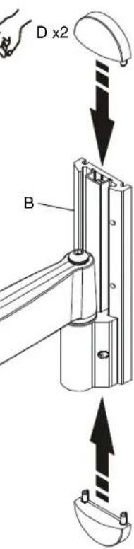
- Align caps (D) with holes in wall plate (B) and slide into position.
3
4
3B
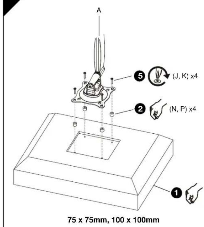
Recessed Mounting Holes
IMPORTANT! This procedure only applicable when 4mm diameter mounting holes are recessed into back surface of display.

WARNING: Exceeding the weight capacity can result in serious personal injury or damage to equipment! It is the installer's responsibility to make sure the combined weight of all components attached to the iCSPDA2 does not exceed 40 lbs (18 kg).
- Carefully place display face down on protective surface.
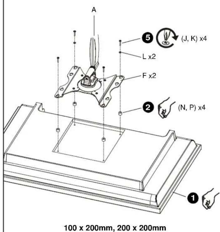
- Place four spacers (N or P, as applicable) over each mounting hole on back of display. Select shortest spacer which will provide adequate fill. All spacers must be same length.
NOTE: 100 × 100 and 200 × 200 mounting hole patterns shown; 75 × 75mm and 100 × 200mm patterns similar.
- Select screw length:
If using spacers (N), then use screws (J).
- If using spacers (P), then use screws (K).
NOTE: If installing screws (J, K) through brackets (F), then also use washers (L) for lower pair of teardrop mounting holes.
- Orient arm assembly (A) so that teardrop mounting holes are aligned with holes in spacers (N or P, as applicable).

CAUTION: Using screws of improper size may damage your display! Proper screws will easily and completely thread into display mounting holes.
- Install screws (J or K, as applicable) through washers (L, if applicable), teardrop mounting holes, and spacers (N or P, as applicable), into display. Tighten all four screws. Do not overtighten!
- Continue with "INSTALL ARM ASSEMBLY TO WALL PLATE."
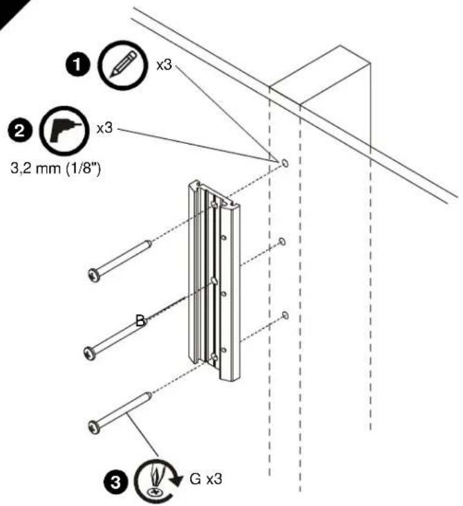
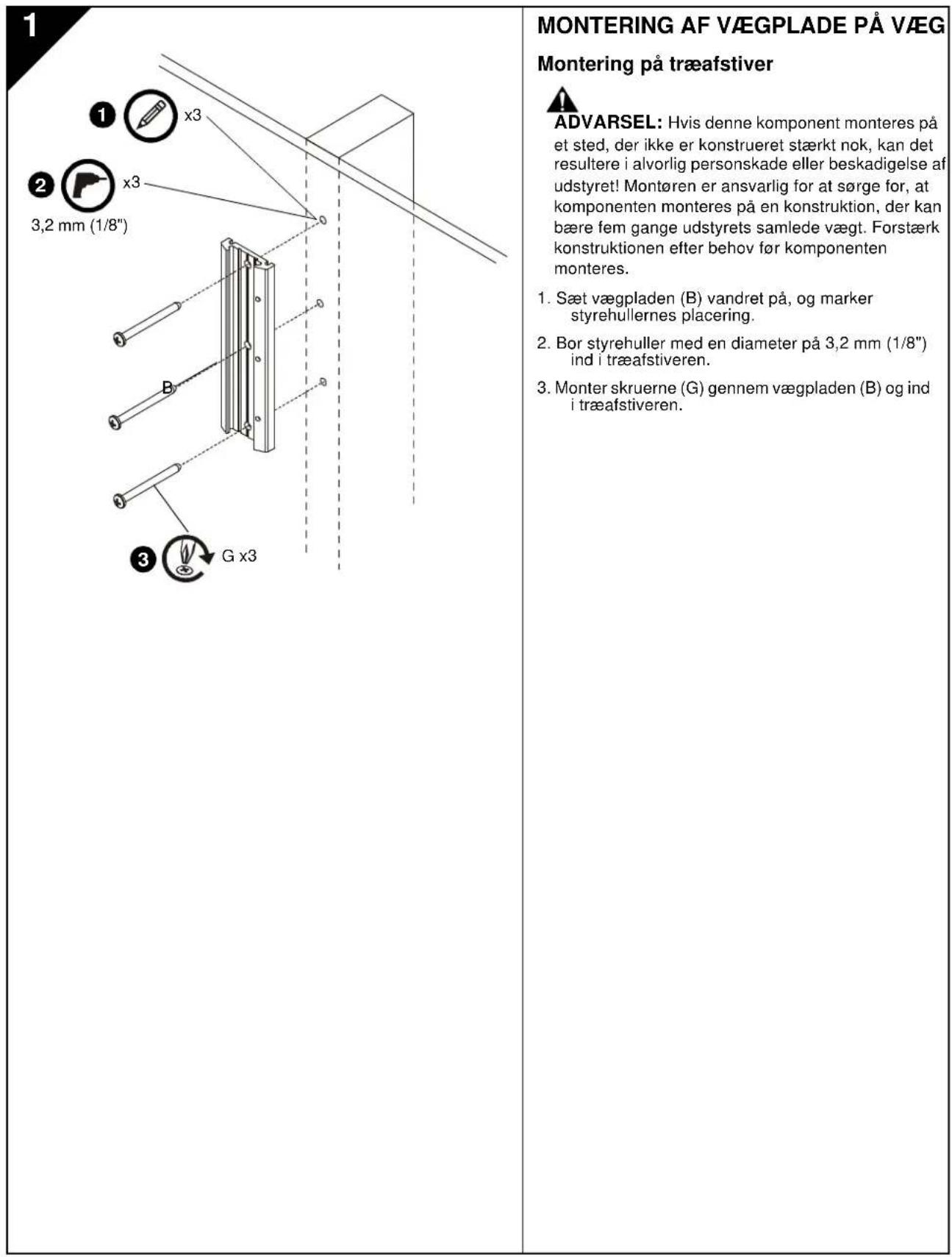
1
INSTALACION DE LA PLACA DE MONTAJE EN PARED
WANDPLAAT AAN WAND BEVESTIGEN
ARMCONSTRUCTIE AAN WANDPLAAT BEVESTIGEN
OTBepctn 100x100 MMx
200x200MM,uaaNohei
75 × 75 mm × 100 × 200 mm
0
- Buxpaatb bntb Hxoho 0nuhb:
EcnwnonbsyntaBtynnN
ONON308aTbBHTb(J)
Ecnna nannnnyoataynn (P) nannnoaonbtae bntn (K).
PIMMEAHHE: EcmBnhtb (J.K) nponyckxotcr
Hep306b(F), Taekoe konno3a8a
Aab6 (L) dna Hauke npn
KanneMkKnKpeneKnxO TaepcTt.
- PACONONOMATH KPOHUIJETB H 605E (A) Tak, UTOHAI KANGAN MOONGKOWOYU OTHOCTO
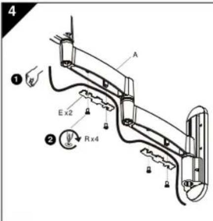
2
MONTERING AF ARMENHED PÅ VæGPLADE
MANUFACTURERS DECLARATION OF CONFORMITY
For
Product identification:
Model/type
iCSPDA2
Category (description)
: Mounting devices, Stands and other Accessories, to be used with entertainment electronics
Brand
iC
Manufacturer:
CSAV Inc.
8401 Eagle Creek Parkway
Savage, MN 55378
EU Representative:
CSAV Inc.
Fellennoord 130 5611
ZB Einhoven
The Netherlands
31(0)402668620
| Concerning | ||||
| EMC | Safety | |||
| A sample of the product has been tested by: | Not Applicable | CSAV Inc. | ||
| Test report reference | . | |||
| Applied standards | EN 60065 :2002 | |||
Means of conformity
We declare under our sole responsibility that this product is in conformity with Directive 93/68/EEC (Marking), 98/37/EC (Machinery) 2001/95/EC (Safety) and/or complies to the essential requirements and all other relevant provisions of the based on test results using (non)harmonized standards in accordance with the Directives mentioned

Manufactured by CHIEF®
iC Mounting Solutions
USA·8401 Eagle Creek Parkway, Suite 700·Savage, Minnesota 55378·800.572.1373
Europe/Middle East/Africa ^+ 31 (0)40 2668620
www.icmounts.com