EVC4BL - Basket CDA - Free user manual and instructions
Find the device manual for free EVC4BL CDA in PDF.
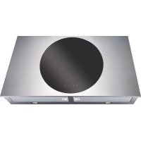
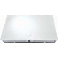
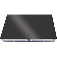
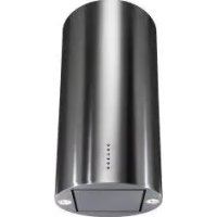
| Product type | Range hood |
| Brand | CDA |
| Model | EVC4BL |
| Installation | External extraction (Fig.1B) or recirculation (Fig.1A) |
| Power supply | Single phase, 220-240V / 50Hz, class II (no earth) |
| Connection | BROWN = L, BLUE = N |
| Number of speeds | 3 speeds + Intense function (10 min) |
| Lighting | Halogen lamps (Fig.15) |
| Controls | 6 buttons: Lighting, Stop, 1st, 2nd, 3rd speed, Automatic stop timer 15 min |
| Special functions | Clean air: runs 10 min/h, Filter saturation indicator, Timer 15 min |
| Grease filter | Acrylic (replace as needed) or metal/aluminium (dishwasher safe) |
| Grease filter maintenance | Wash at least every 2 months |
| Active carbon filter | Not washable, replace every 4 months |
| Safety distance | Minimum 65 cm between cooking surface and lowest part of hood |
| Recommended evacuation diameter | 150 mm |
| Wall installation type | Wall mounting with drilling template, screws and wall plugs |
| Saturation indicator | Button A flashing: every 2 s = wash grease filter; every 0.5 s = change carbon filter |
| Indicator reset | Press button A for 5 s after maintenance |
| Safety instructions | Do not flambé under the hood, avoid backflow, provide ventilation if used simultaneously with non-electric burners |
| Maximum power | See rating plate inside the hood |
Frequently Asked Questions - EVC4BL CDA
User questions about EVC4BL CDA
0 question about this device. Answer the ones you know or ask your own.
Ask a new question about this device
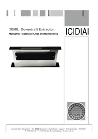
Download the instructions for your Basket in PDF format for free! Find your manual EVC4BL - CDA and take your electronic device back in hand. On this page are published all the documents necessary for the use of your device. EVC4BL by CDA.
USER MANUAL EVC4BL CDA
text_image
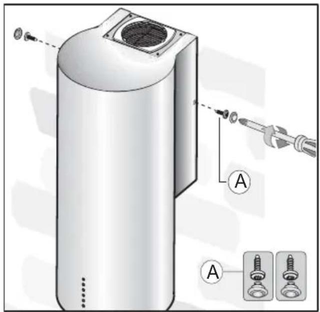
Technical diagram showing a mechanical assembly with labeled components and a magnified inset of a square component, including screw seals.Fig.3
text_image
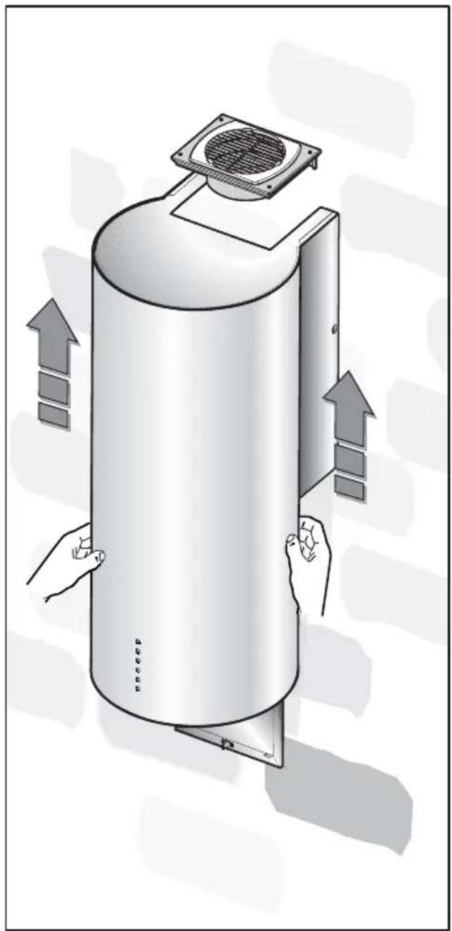
Technical diagram showing assembly of a cylindrical device with labeled parts and directional arrows indicating process flow.Fig.4 Fig.5
flowchart
graph TD
    A["Component 1"] --> B["Component 2"]
    B --> C["Component 3"]
    C --> D["Component 4"]
    D --> E["Component 5"]
    E --> F["Component 6"]
    F --> G["Component 7"]
    G --> H["Component 8"]
    H --> I["Component 9"]
    I --> J["Component 10"]
    J --> K["Component 11"]
    K --> L["Component 12"]
    L --> M["Component 13"]
    M --> N["Component 14"]
    N --> O["Component 15"]
    O --> P["Component 16"]
    P --> Q["Component 17"]
    Q --> R["Component 18"]
    R --> S["Component 19"]
    S --> T["Component 20"]
    T --> U["Component 21"]
    U --> V["Component 22"]
    V --> W["Component 23"]
    W --> X["Component 24"]
    X --> Y["Component 25"]
    Y --> Z["Component 26"]
    Z --> AA["Component 27"]
    AA --> AB["Component 28"]
    AB --> AC["Component 29"]
    AC --> AD["Component 30"]
text_image
Technical diagram of an electronic device with labeled components (E, Y, X, C, D) and a legend for screw assembly.Fig.6
natural_image
Exploded view diagram of a refrigerant air conditioner unit showing internal components and airflow direction (no text or labels)Fig.7
text_image
E C DFig.8
text_image
E C D C DFig.9
text_image
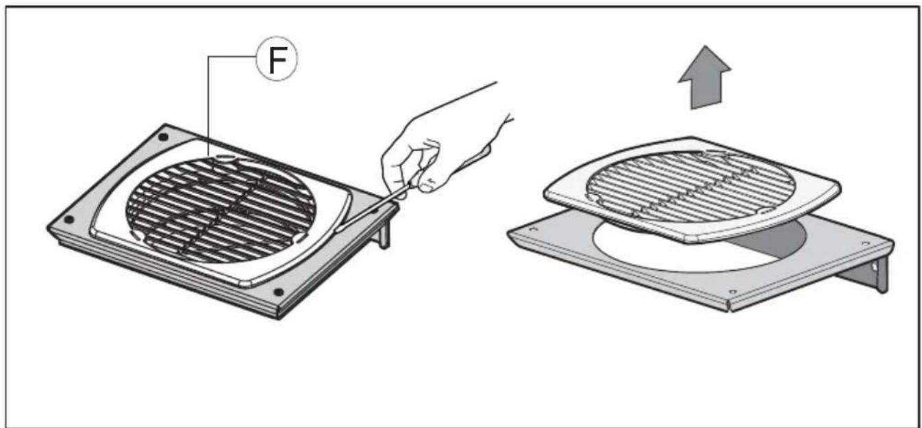
Diagram showing a hand using a tool to clean a fan grille, with an upward arrow indicating the process.Fig.10
natural_image
Illustration of a cylindrical device with heat exchanger and airflow arrows, no text or symbols presentFig.11
text_image
Technical diagram of a cylindrical device with labeled parts and assembly instructions, showing mounting features and component details.Fig.12
text_image
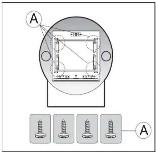
A AFig.13
text_image
Technical diagram showing exploded view of electronic components with labeled parts A, B, and D, including cable routing and wiring connections.Fig.14
text_image
Technical diagram showing installation of a device with labeled components A and D, including hand operating controls and a lamp mechanism.Fig.15
flowchart
graph TD
    A --> 1
    B --> 0
    C --> 1
    D --> 2
    E --> 3
    F --> 1
Fig.16
GENERALITA'
Carefully read the following important information regarding installation safety and maintenance. Keep this information booklet accessible for further consultations.
The appliance has been designed for use as a ducted version (air exhaust to the outside - Fig. 1B), or a filter version (air circulation on the inside - Fig. 1A).
SAFETY PRECAUTION
- Take care when the cooker hood is operating simultaneously with an open fireplace or burner that depend on the air in the environment and are supplied by other than electrical energy, as the cooker hood removes the air from the environment which a burner or fireplace need for combustion. The negative pressure in the environment must not exceed 4Pa (4x10⁻⁵ bar). Provide adequate ventilation in the environment for a safe operation of the cooker hood.
Follow the local laws applicable for external air evacuation.
Before connecting the model to the electricity network:
- control the data plate (positioned inside the appliance) to ascertain that the voltage and power correspond to the network and the socket is suitable. If in doubt ask a qualified electrician.
- If the power supply cable is damaged, it must be replaced with another cable or a special assembly, which may be obtained direct from the manufacturer or from the Technical Assistance Centre.
2. WARNING!
In certain circumstances electrical appliances may be a danger hazard.
A) Do not check the status of the filters while the cooker hood is operating
B) Do not touch bulbs or adjacent areas, during or straight after prolonged use of the lighting installation.
C) Flambè cooking is prohibited underneath the cooker hood
D) Avoid free flame, as it is damaging for the filters and a fire hazard
E) Constantly check food frying to avoid that the overheated oil may become a fire hazard
F) Disconnect the electrical plug prior to any maintenance.
G) This appliance is not intended for use by young children or infirm persons without supervision
H) Young children should be supervised to ensure they do not play with the appliance
I) There shall be adequate ventilation of the room when the rangehood is used at the same time as
appliances burning gas or other fuels L) There is a risk of fire if cleaning is not carried out in accordance with the instructions
This appliance conforms to the European Directive EC/2002/96, Waste Electrical and Electronic Equipment (WEEE). By making sure that this appliance is disposed of in a suitable manner, the user is helping to prevent potential damage to the environment or to public health.
The symbol on the product or on the accompanying
paperwork indicates that the appliance should not be treated as domestic waste, but should be delivered to a suitable electric and electronic appliance recycling collection point. Follow local guidelines when disposing of waste. For more information on the treatment, re-use and recycling of this product, please contact your local authority, domestic waste collection service or the shop where the appliance was purchased.
INSTALLATION INSTRUCTIONS
Assembly and electrical connections must be carried out by specialised personnel.
• Electric Connection
The appliance has been manufactured as a class II, therefore no earth cable is necessary.
The connection to the mains is carried out as follows:
BROWN = L line
BLUE = N neutral
If not provided, connect a plug for the electrical load indicated on the description label. Where a plug is provided, the cooker hood must be installed in order that the plug is easily accessible.
An omnipolar switch with a minimum opening of 3mm between contacts, in line with the electrical load and local standards, must be placed between the appliance and the network in the case of direct connection to the electrical network.
- The minimum distance between the support surfaces of the cooking pots on the cooker top and the lowest part of the cooker hood must be at least 65 cm.
If a connection tube composed of two parts is used, the upper part must be placed outside the lower part. Do not connect the cooker hood exhaust to the same conductor used to circulate hot air or for evacuating fumes from other appliances generated by other than an electrical source.
Before proceeding with the assembly operations, remove the anti-grease filter(s) (Fig.2c) so that the unit is easier to handle.
In the case of assembly of the appliance in the suction version prepare the hole for evacuation of the air.
- We recommend the use of an air exhaust pipe with a diameter of 150. If a pipe with a smaller diameter is used, the efficiency of the product may be reduced and its operation may become noisier
Note!
- When installing this product we recommend you seek the help of another individual.
Please note:
- Before beginning the assembly procedure, for easier cooker hood handling, open the packaging, remove the cooker hood and place it on a convenient surface (Fig. 2a).
Open the panel by pressing the point indicated in Fig. 2b.
Remove the aluminium panel by pulling the handle as indicated in Fig. 2c. If the product is supplied with active charcoal filters, remove them by pulling the lever outwards as indicated in Fig. 2d.
- Hood assembly
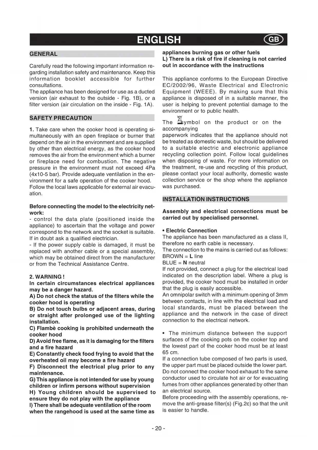
The product is supplied pre-assembled. To install it, proceed as follows:
- Remove the four screws A as indicated in Fig. 3.
- Separate the bodywork from the frame, removing the plugs and then the screws B as indicated in Fig. 4.
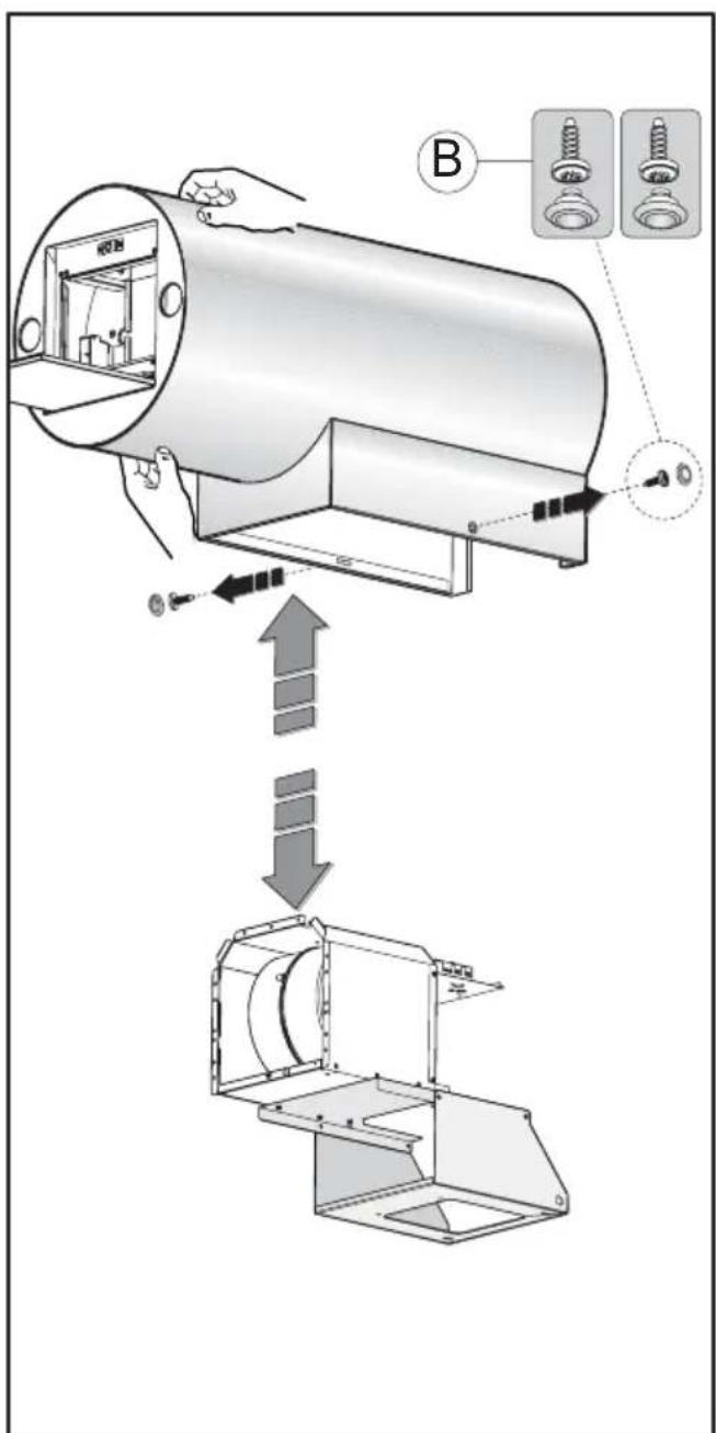
• Fixing the appliance to a wall
- Position the fixing template on the wall (taking the minimum distance from the hob into account).
Mark fixing holes and cut them into the material.
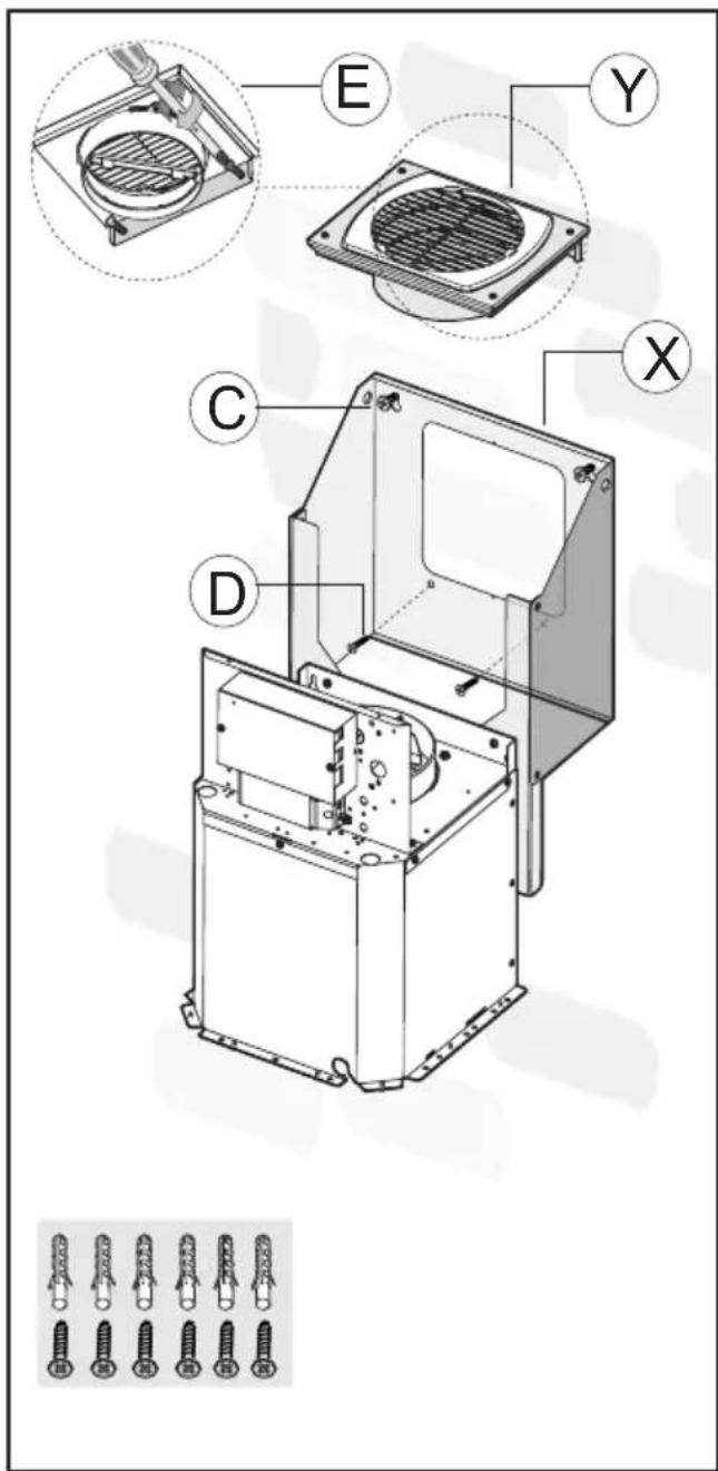
- Fix the 2 screws C and the screw anchors (Fig. 6), without tightening them completely.
- After the necessary adjustments have been made, fix the motor assembly X in place using the 2 screws D (Fig. 6).
- Fix the air outlet bracket Y to the wall using the 2 screws E (Fig. 6).
- Position the motor assembly X against the wall, make sure it is in a horizontal position and tighten the screws C (Fig. 6).
- When carrying out the fixing procedures, use only screws and screw anchors which are suited to the type of wall (e.g. reinforced concrete, plasterboard etc.).
- If the screws and screw anchors are supplied with the appliance, make sure that they are suited to the type of wall to which the hood must be fixed.
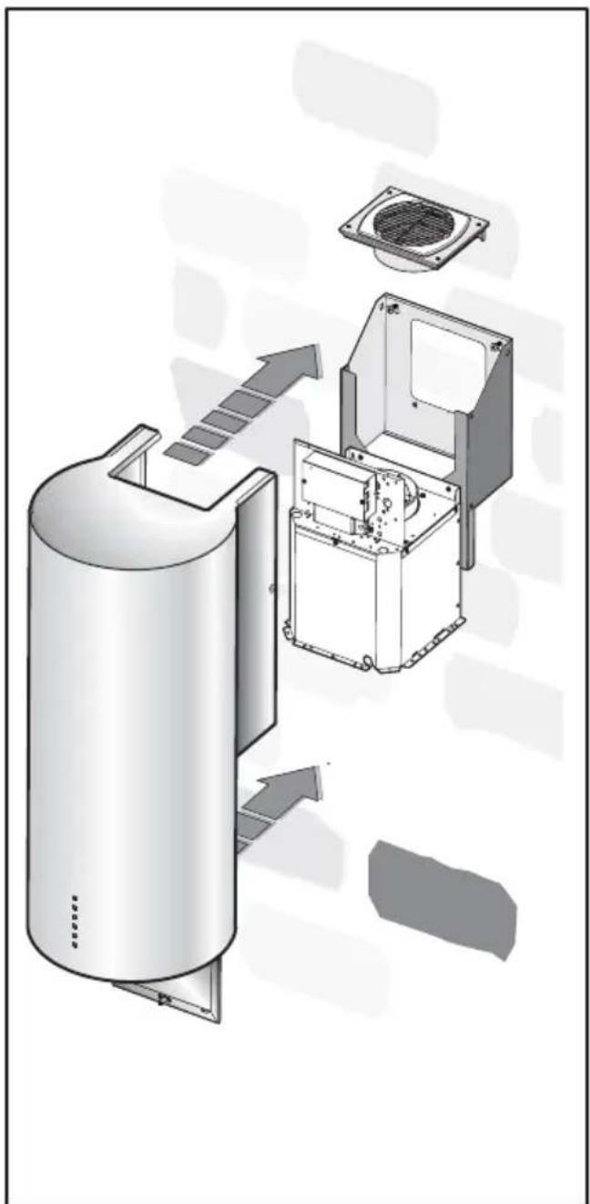
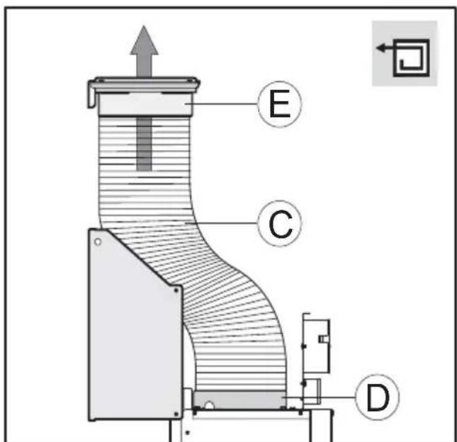
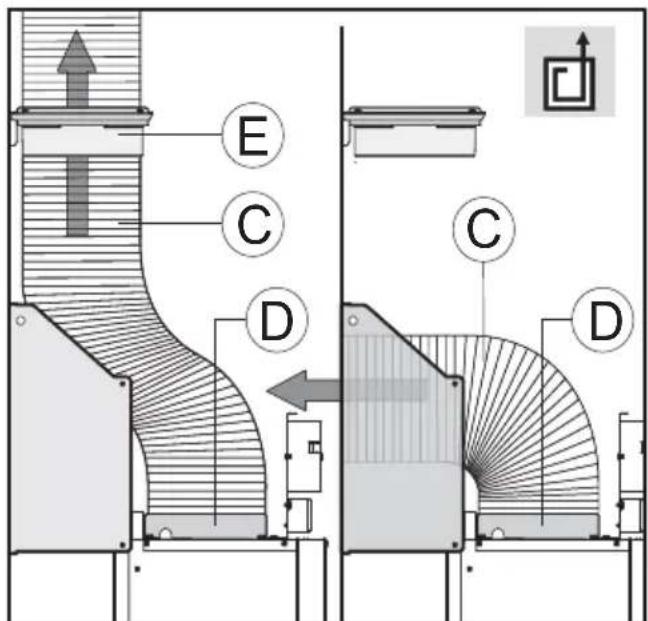
- If your model is a filter version, before fixing the bodywork to the structure, fix the flexible hose C (not supplied) to the air outlet opening D on the hood and the air outlet flange E (Fig. 8).
- If your model is a ducted version, remove the grille F (Fig. 10) only if the air exhaust tube must be passed through the inside of the air outlet bracket E (Fig. 9).
- Connect the flexible hose C to the air outlet D, which
in turn will be connected to the air exhaust hole made previously.
- Position the bodywork A against the wall (Fig. 7) and align it with the frame, pushing it upwards (Fig. 11).
- First, fix the side screws D on the bodywork in place (these are connected to the frame underneath) as indicated in Fig. 12, then tighten the screws A on the lower part of the cooker hood as indicated in Fig. 13.
- Electrical connection
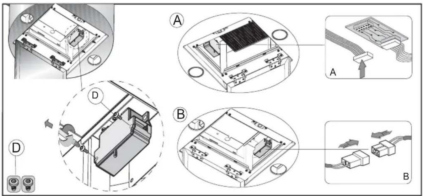
Before performing this connection, loosen the 4 screws D on the two boxes and open the cover panels (Fig. 14).
- Perform the necessary electrical connections between the cooker hood body and the motor assembly (Fig. 14A and B).
USE AND MAINTENANCE
- We recommend that the cooker hood is switched on before any food is cooked. We also recommend that the appliance is left running for 15 minutes after the food is cooked, in order to thoroughly eliminate all contaminated air.
The effective performance of the cooker hood depends on constant maintenance; the anti-grease filter and the active carbon filter both require special attention.
- The anti-grease filter is used to trap any grease particles suspended in the air, therefore is subject to saturation (the time it takes for the filter to become saturated depends on the way in which the appliance is used).
The acrylic filter, which is found resting on the grille, should be replaced when the text, visible through the grille, changes colour and the ink spreads; the new filter should be fitted in such a way that the text can be seen through the grille from outside the cooker hood.
If the filters do not have any text on them, or if metal filters or aluminium panel filters are used, they should be washed every 2 months in order to prevent the risk of fire. To wash the filters, proceed as follows:
- Remove the filter from the grille and wash it using a solution of water and neutral liquid detergent, leaving the dirt to soften.
- Rinse thoroughly with warm water and leave to dry. The metal filters and/or aluminium panel are also dishwasher safe. If the filters are made using aluminium, or if an aluminium panel is used, after a few washes the colour may change. This does not mean they have to be replaced.
If the replacement and washing instructions are not followed, the anti-grease filters may present a fire hazard.
- The active carbon filters are used to purify the air which is released back into the room. The filters are not washable or re-usable and must be replaced at least once every four months. The active carbon filter
saturation level depends on the frequency with which the appliance is used, the type of cooking performed and the regularity with which the anti-grease filters are cleaned.
- Remove build-up from the fan and other surfaces of the cooker hood regularly using a cloth moistened with denatured alcohol or non-abrasive neutral liquid detergent.
- The light on the cooker hood is designed for use during cooking and not for general room illumination. Extended use of the light reduces the average duration of the bulb.
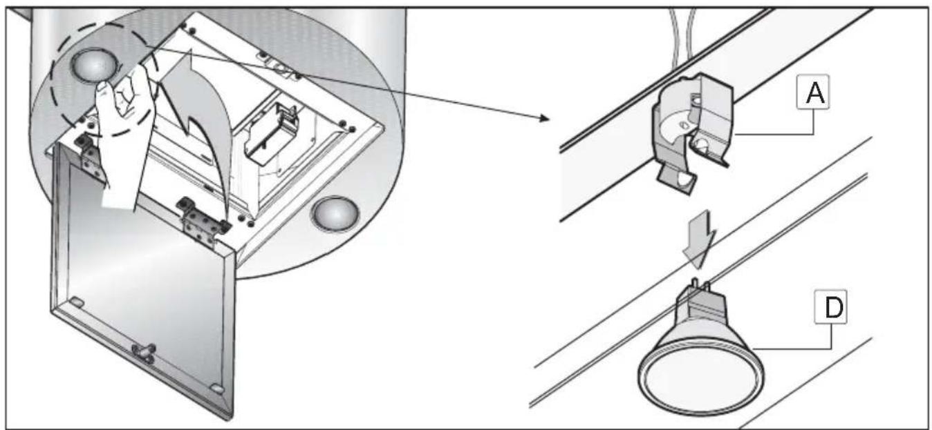
- Replacing halogen light bulbs (Fig. 15).
To replace the halogen lamps B, from the inside of the cooker hood press downwards with two fingers as shown in Fig. 15.
Replace the bulbs with new ones of the same type.
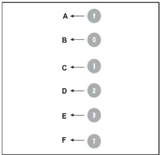
- COMMANDS: (Fig.16) LUMINOUS the key symbols are explained below:
A = LIGHT
B = OFF
C = SPEED I
D = SPEED II
E = SPEED III
F = AUTOMATIC STOP TIMER - 15 minutes
- If your appliance does not have the INTENSIVE speed function, press key E for two seconds and it will be activated for 10 minutes after which it will return to the previously set speed.
When the function is active the LED flashes. To interrupt it before the 10 minutes have expired press key E again.
- By pressing key F for two seconds (with the hood switched off) the “clean air” function is activated. This function switches the appliance on for ten minutes every hour at the first speed. As soon as this function is activated the motor starts up at the first speed for ten minutes, During this time key F and key C must flash at the same time.
After ten minutes the motor switches off and the LED of key F remains switched on with a fixed light until the motor starts up again at the first speed after fifty minutes and keys F and C start to flash again for ten minutes and so on.
By pressing any key for the exclusion of the hood light the hood will return immediately to its normal functioning (e.g. if key D is pressed the “clean air” function is deactivated and the motor moves to the 2nd speed straight away. By pressing key B the function is deactivated).
• Active carbon/grease filter saturation:
- When button A flashes at a frequency of 2 seconds, the grease filters must be cleaned.
- When button A flashes at a frequency of 0.5 seconds, the carbon filters must be replaced.
After the clean filter has been replaced, the electronic memory must be reset by pressing button A for approximately 5 seconds, until the light on the button stops flashing.
THE MANUFACTURER DECLINES ALL RESPONSIBILITY FOR EVENTUAL DAMAGES CAUSED BY BREACHING THE ABOVE WARNINGS.
ALGEMEEN
INSTALLATIE INSTRUCTIES
C = knop EERSTE SNELHEID
D = knop TWEEDW DERDE SNELHEID
E = knop DERDE SNELHEID
F = knop TIMER AUTOMATISCHE ONDERBREKING na 15 minuten
natural_image
Black-and-white map of Europe showing country borders (no text or labels)3LIK0376