
FM2A75M Pro4+ - Motherboard ASROCK - Free user manual and instructions
Find the device manual for free FM2A75M Pro4+ ASROCK in PDF.

| Product Type | Motherboard |
| Brand | ASRock |
| Model | FM2A75M Pro4+ |
| Form Factor | Micro ATX |
| CPU Socket | FM2+ (compatible with FM2) |
| Chipset | AMD A75 FCH (Hudson-D3) |
| Memory Type | Non-ECC DDR3, unbuffered |
| Number of Memory Slots | 4 x DIMM (dual channel) |
| Maximum Memory Capacity | 64 GB |
| Supported Memory Frequencies | DDR3 1866/1600/1333/1066 |
| Expansion Slots | 1 x PCIe 3.0 x16, 1 x PCIe 2.0 x16 (x4), 1 x PCIe 2.0 x1, 1 x PCI |
| Integrated Graphics | AMD Radeon HD 8000/7000 (depending on APU) |
| Video Outputs | D-Sub, DVI-D, HDMI (triple monitor) |
| Maximum Resolution | HDMI up to 1920x1200, DVI-D up to 2560x1600 |
| Audio | 7.1 CH HD (Realtek ALC892) |
| Network | Gigabit LAN (Qualcomm Atheros AR8171) |
| SATA Ports | 6 x SATA 6 Gb/s (RAID 0,1,10) |
| Rear USB Ports | 4 x USB 2.0, 2 x USB 3.0 |
| USB Ports (internal) | 3 x USB 2.0 headers (6 ports), 1 x USB 3.0 header (2 ports) |
| Power Connectors | ATX 24-pin, ATX 12V 8-pin |
| BIOS | AMI UEFI 64 MB, multilingual |
| Supported Operating Systems | Windows 8.1/8/7 (32/64-bit) |
| Certifications | FCC, CE, WHQL, ErP/EuP |
| Package Contents | Motherboard, quick installation guide, support CD, 2 SATA cables, I/O shield |
| Special Features | Solid capacitors, Home Cloud, AMD CrossFireX, triple monitor |
Frequently Asked Questions - FM2A75M Pro4+ ASROCK
User questions about FM2A75M Pro4+ ASROCK
0 question about this device. Answer the ones you know or ask your own.
Ask a new question about this device
Download the instructions for your Motherboard in PDF format for free! Find your manual FM2A75M Pro4+ - ASROCK and take your electronic device back in hand. On this page are published all the documents necessary for the use of your device. FM2A75M Pro4+ by ASROCK.
USER MANUAL FM2A75M Pro4+ ASROCK
No part of this documentation may be reproduced, transcribed, transmitted, or translated in any language, in any form or by any means, except duplication of documentation by the purchaser for backup purpose, without written consent of ASRock Inc.
Products and corporate names appearing in this documentation may or may not be registered trademarks or copyrights of their respective companies, and are used only for identification or explanation and to the owners' benefit, without intent to infringe.
Disclaimer:
Specifications and information contained in this documentation are furnished for informational use only and subject to change without notice, and should not be constructed as a commitment by ASRock. ASRock assumes no responsibility for any errors or omissions that may appear in this documentation.
With respect to the contents of this documentation, ASRock does not provide warranty of any kind, either expressed or implied, including but not limited to the implied warranties or conditions of merchantability or fitness for a particular purpose.
In no event shall ASRock, its directors, officers, employees, or agents be liable for any indirect, special, incidental, or consequential damages (including damages for loss of profits, loss of business, loss of data, interruption of business and the like), even if ASRock has been advised of the possibility of such damages arising from any defect or error in the documentation or product.
The terms HDMI ^™ and HDMI High-Definition Multimedia Interface, and the HDMI logo are trademarks or registered trademarks of HDMI Licensing LLC in the United States and other countries.

This device complies with Part 15 of the FCC Rules. Operation is subject to the following two conditions:
(1) this device may not cause harmful interference, and
(2) this device must accept any interference received, including interference that may cause undesired operation.
CALIFORNIA, USA ONLY
The Lithium battery adopted on this motherboard contains Perchlorate, a toxic substance controlled in Perchlorate Best Management Practices (BMP) regulations passed by the California Legislature. When you discard the Lithium battery in California, USA, please follow the related regulations in advance.
"Perchlorate Material-special handling may apply, see www.dtsc.ca.gov/hazardouswaste/perchlorate"
The terms HDMI ^™ and HDMI High-Definition Multimedia Interface, and the HDMI logo are trademarks or registered trademarks of HDMI Licensing LLC in the United States and other countries.
Motherboard Layout
text_image
ASRock FM2A75MPro4+ PCIE1 Super I/O PCIE2 CMOS BATTERY XFastRAM PCI3 RoHS PCI1 PCIE3 AMD A75FCH (Hudson-D3) Chipset ATXPWR1 ATXPMWR1 FrontUSB3.0 PCIExpress3.0 DDR3_A1(64bit,240-pinmodule) DDR3_A2(64bit,240-pinmodule) DDR3_B1(64bit,240-pinmodule) DDR3_B2(64bit,240-pinmodule) PCI1 PCI2 PCI3 PCI4 PCI5 PCI6 PCI7 PCI8 PCI9 PCI10 PCI11 PCI12 PCI13 PCI14 PCI15 PCI16 PCI17 PCI18 PCI19 PCI20 PCI21 PCI22 PCI23 PCI24 PCI25 PCI26 PCI27 PCI28 PCI29 PCI30 PCI31 PCI32 PCI33 PCI34 PCI35 PCI36 PCI37 PCI38 PCI39 PCI40 PCI41 PCI42 PCI43 PCI44 PCI45 PCI46 PCI47 PCI48 PCI49 PCI50 PCI51 PCI52 PCI53 PCI54 PCI55 PCI56 PCI57 PCI58 PCI59 PCI60 PCI61 PCI62 PCI63 PCI64 PCI65 PCI66 PCI67 PCI68 PCI69 PCI70 PCI71 PCI72 PCI73 PCI74 PCI75 PCI76 PCI77 PCI78 PCI79 PCI80 PCI81 PCI82 PCI83 PCI84 PCI85 PCI86 PCI87 PCI88 PCI89 PCI90 PCI91 PCI92 PCI93 PCI94 PCI95 PCI96 PCI97 PCI98 PCI99 PCI100No. Description
1 Power Fan Connector (PWR_FAN1)
2 ATX 12V Power Connector (ATX12V1)
3 CPU Fan Connector (CPU_FAN1)
4 CPU Fan Connector (CPU_FAN2)
5 2 x 240-pin DDR3 DIMM Slots (DDR3_A1, DDR3_B1)
6 2 x 240-pin DDR3 DIMM Slots (DDR3_A2, DDR3_B2)
7 ATX Power Connector (ATXPWR1)
8 USB 3.0 Header (USB3_3_4)
9 Clear CMOS Jumper (CLRCMOS1)
10 SATA3 Connector (SATA3_6)
11 SATA3 Connector (SATA3_5)
12 SATA3 Connector (SATA3_4)
13 SATA3 Connector (SATA3_3)
14 SATA3 Connector (SATA3_1)
15 SATA3 Connector (SATA3_2)
16 System Panel Header (PANEL1)
17 Power LED Header (PLED1)
18 Chassis Speaker Header (SPEAKER1)
19 USB 2.0 Header (USB_5_6)
20 USB 2.0 Header (USB_7_8)
21 USB 2.0 Header (USB_9_10)
22 TPM Header (TPMS1)
23 Print Port Header (LPT1)
24 COM Port Header (COM1)
25 Infrared Module Header (IR1)
26 Front Panel Audio Header (HD_AUDIO1)
27 Chassis Intrusion Header (CI1)
28 Chassis Fan Connector (CHA_FAN1)
I/O Panel

text_image
Diagram showing labeled electronic device ports and connectors, including server, VGA, port, and keyboard/monitor components.No. Description No. Description
1 USB 2.0 Ports (USB_3_4)* 8 Microphone (Pink)
2 D-Sub Port 9 Optical SPDIF Out Port
3 LAN RJ-45 Port** 10 USB 2.0 Ports (USB_1_2)*
4 Central / Bass (Orange) 11
USB 3.0 Ports (USB3_1_2)
(AMD A75 FCH (Hudson-D3))
5 Rear Speaker (Black) 12 HDMI Port
6 Line In (Light Blue) 13 DVI-D Port
7 Front Speaker (Lime)*** 14 PS/2 Mouse/Keyboard Port
* It is recommended to install the USB Keyboard/Mouse cable to USB 2.0 ports (USB_1_2 or USB_3_4) instead of USB 3.0 ports.
** There are two LEDs on the LAN port. Please refer to the table below for the LAN port LED indications.

Activity / Link LED Speed LED Status Description Status Description
| Off No Link Off | 10Mbps connection | |
| Blinking Data A | Activity Orange 100Mbps connection | |
| On Link Green | 1Gbps connection |
*** If you use a 2-channel speaker, please connect the speaker's plug into "Front Speaker Jack". See the table below for connection details in accordance with the type of speaker you use.
| Audio Output Channels | Front Speaker (No. 7) | Rear Speaker (No. 5) | Central / Bass (No. 4) | Line In or Side Speaker (No. 6) |
| 2 V -- -- -- | ||||
| 4 V V -- -- | ||||
| 6 V V V -- | ||||
| 8 V V V V |
To enable Multi-Streaming, you need to connect a front panel audio cable to the front panel audio header. After restarting your computer, you will find the "Mixer" tool on your system. Please select "Mixer ToolBox", click "Enable playback multi-streaming", and click "ok". Choose "2CH", "4CH", "6CH", or "8CH" and then you are allowed to select "Realtek HDA Primary output" to use the Rear Speaker, Central/Bass, and Front Speaker, or select "Realtek HDA Audio 2nd output" to use the front panel audio.
1. Introduction
Thank you for purchasing ASRock FM2A75M Pro4+ motherboard, a reliable motherboard produced under ASRock's consistently stringent quality control. It delivers excellent performance with robust design conforming to ASRock's commitment to quality and endurance.
This Quick Installation Guide contains introduction of the motherboard and step-by-step installation guide. More detailed information of the motherboard can be found in the user manual presented in the Support CD.
Because the motherboard specifications and the BIOS software might be updated, the content of this manual will be subject to change without notice. In case any modifications of this manual occur, the updated version will be available on ASRock website without further notice. You may find the latest VGA cards and CPU support lists on ASRock website as well. ASRock website http://www.asrock.com If you require technical support related to this motherboard, please visit our website for specific information about the model you are using. www.asrock.com/support/index.asp
1.1 Package Contents
ASRock FM2A75M Pro4+ Motherboard (Micro ATX Form Factor)
ASRock FM2A75M Pro4+ Quick Installation Guide
ASRock FM2A75M Pro4+ Support CD
2 x Serial ATA (SATA) Data Cables (Optional)
1 x I/O Panel Shield

ASRock Reminds You...
To get better performance in Windows® 8 / 8 64-bit / 7 / 7 64-bit, it is recommended to set the BIOS option in Storage Configuration to AHCI mode. For the BIOS setup, please refer to the "User Manual" in our support CD for details.
1.2 Specifications
| Platform - Micro ATX Form Factor- All Solid Capacitor design |
| A-Style - Home Cloud |
| CPU - Supports Socket FM2+ 95W / FM2 100W processors- 4 + 2 Power Phase design |
| Chipset - AMD A75 FCH (Hudson-D3) |
| Memory - Dual Channel DDR3 Memory Technology- 4 x DDR3 DIMM Slots-Supports DDR3 1866/1600/1333/1066 non-ECC, un-buffered memory (seeCAUTION 1)- Max. capacity of system memory: 64GB (seeCAUTION 2)- Supports Intel® Extreme Memory Profile (XMP) 1.3 / 1.2- Supports AMD Memory Profile (AMP) |
| Expansion Slot - 1 x PCI Express 3.0 x16 Slot (PCIE1 @ x16 mode)* PCIE 3.0 is only supported with FM2+ CPU. With FM2CPU, it only supports PCIE 2.0.- 1 x PCI Express 2.0 x16 Slot (PCIE3 @ x4 mode)- 1 x PCI Express 2.0 x1 Slot- 1 x PCI Slot- Supports AMD Quad CrossFireXTM, CrossFireXTM and Dual Graphics |
| Graphics - Integrated AMD Radeon HD 8000/7000 series graphics in A-series APU-DirectX 11.1, Pixel Shader 5.0 with FM2+ CPU. DirectX 11,Pixel Shader 5.0 with FM2 CPU.- Max. shared memory 2GB- Three VGA output options: D-Sub, DVI-D and HDMI Ports-Supports Triple Monitor-Supports HDMI Technology with max. resolution up to 1920x1200 @ 60Hz-Supports Dual-link DVI-D with max. resolution up to 2560x1600 @ 60Hz-Supports D-Sub with max. resolution up to 1920x1200 @ 60Hz-Supports Auto Lip Sync, Deep Color (12bpc), xvYCC and HBR (High Bit Rate Audio) with HDMI Port (Compliant HDMI monitor is required) (seeCAUTION 3)- Supports Blu-ray Stereoscopic 3D with HDMI Port |
| - Supports AMD Steady Video processing capability for automatic jitter reduction on home/online video- Supports HDCP with DVI-D and HDMI Ports- Supports Full HD 1080p Blu-ray (BD) playback with DVI-D and HDMI Ports | TM 2.0: New video post |
| Audio - 7.1 CH HD Audio with Content Protection (Realtek ALC892 Audio Codec)- Premium Blu-ray Audio support | |
| LAN - PCIE x1 Gigabit LAN 10/100/1000 Mb/s- Qualcomm® Atheros® AR8171- Supports Qualcomm® Atheros® Security Wake On Internet Technology- Supports Wake-On-LAN- Supports Energy Efficient Ethernet 802.3az- Supports PXE | |
| Rear Panel I/O - 1 x PS/2 Mouse/Keyboard Port- 1 x D-Sub Port- 1 x DVI-D Port- 1 x HDMI Port- 1 x Optical SPDIF Out Port- 4 x USB 2.0 Ports- 2 x USB 3.0 Ports (AMD A75 FCH (Hudson-D3))- 1 x RJ-45 LAN Port with LED (ACT/LINK LED and SPEED LED)- HD Audio Jacks: Rear Speaker/Central/Bass/Line in/Front Speaker/Microphone | |
| Storage - 6 x SATA3 6.0 Gb/s Connectors, support RAID (RAID 0, RAID 1 and RAID 10), NCQ, AHCI and Hot Plug | |
| Connector - 1 x IR Header- 1 x Print Port Header- 1 x COM Port Header- 1 x Chassis Intrusion Header- 1 x TPM Header- 1 x Power LED Header- 2 x CPU Fan Connectors (1 x 4-pin, 1 x 3-pin)- 1 x Chassis Fan Connector (4-pin)- 1 x Power Fan Connector (3-pin)- 1 x 24 pin ATX Power Connector- 1 x 8 pin 12V Power Connector- 1 x Front Panel Audio Connector | |
| - 3 x USB 2.0 Headers (Support 6 USB 2.0 ports)- 1 x USB 3.0 Header by AMD A75 FCH (Hudson-D3)(Supports 2 USB 3.0 ports) | |
| BIOS Feature - 64Mb AMI UEFI Legal BIOS with GUI support- Supports “Plug and Play”- ACPI 1.1 compliance wake up events- Supports jumperfree- SMBIOS 2.3.1 support- DRAM, CPU Voltage multi-adjustment | |
| Support CD - Drivers, Utilities, AntiVirus Software (Trial Version),CyberLink MediaEspresso 6.5 Trial, Google ChromeBrowser and Toolbar, Start8 (30 days trial) | |
| Hardware - CPU temperature sensingMonitor - Chassis temperature sensing- CPU Fan Tachometer- Chassis Fan Tachometer- CPU/Chassis Quiet Fan- CPU/Chassis Fan multi-speed control- CASE OPEN detection- Voltage monitoring: +12V, +5V, +3.3V, Vcore | |
| OS - Microsoft® Windows® 8.1 32-bit / 8.1 64-bit / 8 32-bit /8 64-bit / 7 32-bit / 7 64-bit | |
| Certifications - FCC, CE, WHQL- ErP/EuP ready (ErP/EuP ready power supply is required) | |
* For detailed product information, please visit our website: http://www.asrock.com
WARNING
Please realize that there is a certain risk involved with overclocking, including adjusting the setting in the BIOS, applying Untied Overclocking Technology, or using third-party overclocking tools. Overclocking may affect your system's stability, or even cause damage to the components and devices of your system. It should be done at your own risk and expense. We are not responsible for possible damage caused by overclocking.
CAUTION!
- Whether 1866/1600MHz memory speed is supported depends on the CPU you adopt. If you want to adopt DDR3 1866/1600 memory module on this motherboard, please refer to the memory support list on our website for the compatible memory modules.
ASRock website http://www.asrock.com
-
Due to the operating system limitation, the actual memory size may be less than 4GB for the reservation for system usage under Windows ^® 8 / 7. For Windows ^® 64-bit OS with 64-bit CPU, there is no such limitation. You can use ASRock XFast RAM to utilize the memory that Windows ^® cannot use.
-
xvYCC and Deep Color are only supported under Windows ^® 864-bit / 8 / 7 64-bit / 7. Deep Color mode will be enabled only if the display supports 12bpc in EDID. HBR is supported under Windows ^® 864-bit / 8 / 7 64-bit / 7.
1.3 Unique Features
ASRock A-Tuning
A-Tuning is ASRock's multi purpose software suite with a new interface, more new features and improved utilities, including XFast RAM, Dehumidifier, Good Night LED, FAN-Tastic Tuning, OC Tweaker and a whole lot more.
ASRock Instant Boot
ASRock Instant Boot allows you to turn on your PC in just a few seconds, provides a much more efficient way to save energy, time, money, and improves system running speed for your system. It leverages the S3 and S4 ACPI features which normally enable the Sleep/Standby and Hibernation modes in Windows ^® to shorten boot up time. By calling S3 and S4 at specific timing during the shutdown and startup process, Instant Boot allows you to enter your Windows ^® desktop in a few seconds.
ASRock Instant Flash
ASRock Instant Flash is a BIOS flash utility embedded in Flash ROM. This convenient BIOS update tool allows you to update system BIOS without entering operating systems first like MS-DOS or Windows®. With this utility, you can press the
ASRock APP Charger
If you desire a faster, less restricted way of charging your Apple devices, such as iPhone/iPad/iPod Touch, ASRock has prepared a wonderful solution for you - ASRock APP Charger. Simply install the APP Charger driver, it makes your iPhone charge much quickly from your computer and up to 40% faster than before. ASRock APP Charger allows you to quickly charge many Apple devices simultaneously and even supports continuous charging when your PC enters into Standby mode (S1),
Suspend to RAM (S3), hibernation mode (S4) or power off (S5). With APP Charger driver installed, you can easily enjoy the marvelous charging experience.
ASRock XFast USB
ASRock XFast USB can boost USB storage device performance. The performance may depend on the properties of the device.
ASRock XFast LAN
ASRock XFast LAN provides a faster internet access, which includes the benefits listed below. LAN Application Prioritization: You can configure your application's priority ideally and/or add new programs. Lower Latency in Game: After setting online game's priority higher, it can lower the latency in games. Traffic Shaping: You can watch Youtube HD videos and download simultaneously. Real-Time Analysis of Your Data: With the status window, you can easily recognize which data streams you are transferring currently.
ASRock XFast RAM
ASRock XFast RAM is included in A-Tuning. It fully utilizes the memory space that cannot be used under Windows® 32-bit operating systems. ASRock XFast RAM shortens the loading time of previously visited websites, making web surfing faster than ever. And it also boosts the speed of Adobe Photoshop 5 times faster. Another advantage of ASRock XFast RAM is that it reduces the frequency of accessing your SSDs or HDDs in order to extend their lifespan.
ASRock Crashless BIOS
ASRock Crashless BIOS allows users to update their BIOS without fear of failing. If power loss occurs during the BIOS update process, ASRock Crashless BIOS will automatically finish the BIOS update procedure after regaining power. Please note that BIOS files need to be placed in the root directory of your USB disk. Only USB2.0 ports support this feature.
ASRock OMG (Online Management Guard)
Administrators are able to establish an internet curfew or restrict internet access at specified times via OMG. You may schedule
the starting and ending hours of internet access granted to other users. In order to prevent users from bypassing OMG, guest accounts without permission to modify the system time are required.
ASRock Internet Flash
ASRock Internet Flash searches for available UEFI firmware updates from our servers. In other words, the system can auto-detect the latest UEFI from our servers and flash them without entering Windows ^® OS.
ASRock UEFI System Browser
ASRock UEFI system browser is a useful tool included in graphical UEFI. It can detect the devices and configurations that users are currently using in their PC. With the UEFI system browser, you can easily examine the current system configuration in UEFI setup.
ASRock UEFI Tech Service
Contact ASRock Tech Service by sending a support request from the UEFI setup utility if you are having trouble with your PC.
ASRock On/Off Play Technology
ASRock On/Off Play Technology allows users to enjoy the great audio experience from the portable audio devices, such like MP3 player or mobile phone to your PC, even when the PC is turned off (or in ACPI S5 mode)! This motherboard also provides a free 3.5mm audio cable (optional) that ensures users the most convenient computing environment.
ASRock Dehumidifier Function
Users may prevent motherboard damages due to dampness by enabling “Dehumidifier Function”. When enabling Dehumidifier Function, the computer will power on automatically to dehumidify the system after entering S4/S5 state.
ASRock Easy RAID Installer
ASRock Easy RAID Installer can help you to copy the RAID driver from a support CD to your USB storage device. After copying the RAID driver to your USB storage device, please change "SATA Mode" to "RAID", then you can start installing the OS in RAID mode.
ASRock Easy Driver Installer
For users that don't have an optical disk drive to install the drivers from our support CD, Easy Driver Installer is a handy tool in the UEFI that installs the LAN driver to your system via an USB storage device, then downloads and installs the other required drivers automatically.
ASRock Interactive UEFI
ASRock Interactive UEFI is a blend of system configuration tools, cool sound effects and stunning visuals. The unprecedented UEFI provides a more attractive interface and brings a lot more amusing.
ASRock Fast Boot
With ASRock's exclusive Fast Boot technology, it takes less than 1.5 seconds to logon to Windows ^® 8 from a cold boot. No more waiting! The speedy boot will completely change your user experience and behavior.
ASRock X-Boost
Brilliantly designed for combo overclocking, ASRock X-Boost Technology is able to unleash the hidden power of your CPUs. Simply press "X" when turning on the PC, X-Boost will automatically overclock the relative components to get up to 15.77% performance boost! With the smart X-Boost, overclocking CPU can become a near one-button process.
ASRock Restart to UEFI
Windows ^® 8 brings the ultimate boot up experience. The lightning boot up speed makes it hard to access the UEFI setup. AS-Rock Restart to UEFI technology is designed for those requiring frequent UEFI access. It is included in ASRock's exclusive all-in-one A-Tuning tuning program that allows users to easily enter the UEFI automatically when turning on the PC next time. Just
simply enable this function; the PC will be assured to access the UEFI directly in the very beginning.
ASRock USB Key
In a world where time is money, why waste precious time everyday typing usernames to log in to Windows? Why should we even bother memorizing those foot long passwords? Just plug in the USB Key and let your computer log in to windows automatically!
ASRock FAN-Tastic Tuning
ASRock FAN-Tastic Tuning is included in A-Tuning. Configure up to five different fan speeds using the graph. The fans will automatically shift to the next speed level when the assigned temperature is met.
2. Installation
This is a Micro ATX form factor motherboard. Before you install the motherboard, study the configuration of your chassis to ensure that the motherboard fits into it.
Pre-installation Precautions
Take note of the following precautions before you install motherboard components or change any motherboard settings.

Before you install or remove any component, ensure that the power is switched off or the power cord is detached from the power supply. Failure to do so may cause severe damage to the motherboard, peripherals, and/or components.
- Unplug the power cord from the wall socket before touching any component.
- To avoid damaging the motherboard components due to static electricity, NEVER place your motherboard directly on the carpet or the like. Also remember to use a grounded wrist strap or touch a safety grounded object before you handle components.
- Hold components by the edges and do not touch the ICs.
- Whenever you uninstall any component, place it on a grounded anti-static pad or in the bag that comes with the component.
- When placing screws into the screw holes to secure the motherboard to the chassis, please do not over-tighten the screws! Doing so may damage the motherboard.
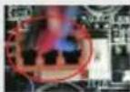
2.1 CPU Installation
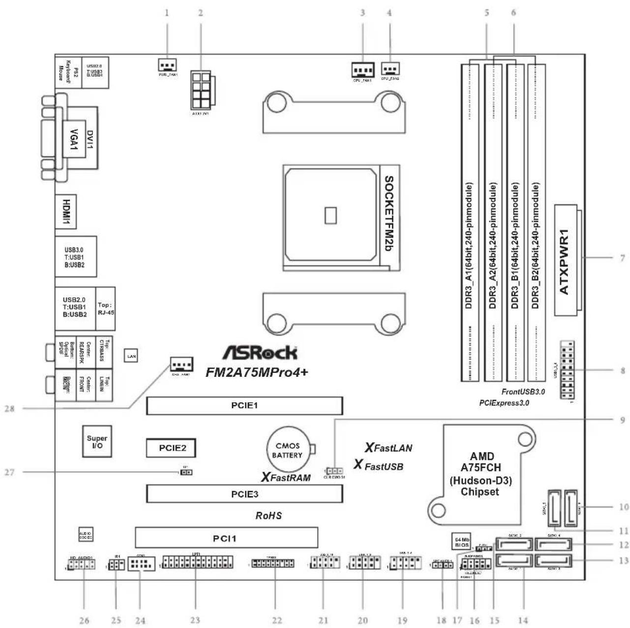
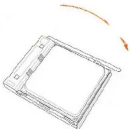
Step 1. Unlock the socket by lifting the lever up to a 90 ° angle.
natural_image
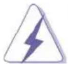
Diagram of a square electronic component with a central square and a vertical rod, showing an orange curved arrow indicating rotation or movement (no text or symbols present)Step 2. Position the CPU directly above the socket such that the CPU corner with the golden triangle matches the socket corner with a small triangle.
Step 3. Carefully insert the CPU into the socket until it fits in place.
natural_image
Technical line drawing of a square mechanical component with a protruding rod and an orange circle highlighting a feature (no text or symbols)
The CPU fits only in one correct orientation. DO NOT force the CPU into the socket to avoid bending of the pins.
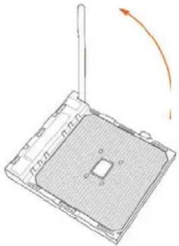
Step 4. When the CPU is in place, press it firmly on the socket while you push down the socket lever to secure the CPU. The lever clicks on the side tab to indicate that it is locked.
natural_image
Simple line drawing of a rectangular device with a curved arrow indicating rotation (no text or symbols)2.2 Installation of CPU Fan and Heatsink
After you install the CPU into this motherboard, it is necessary to install a larger heatsink and cooling fan to dissipate heat. You also need to spray thermal grease between the CPU and the heatsink to improve heat dissipation. Make sure that the CPU and the heatsink are securely fastened and in good contact with each other. Then connect the CPU fan to the CPU FAN connector (CPU_FAN1, see Page 2, No. 3 or CPU_FAN2, see Page 2, No. 4). For proper installation, please kindly refer to the instruction manuals of the CPU fan and the heatsink.
2.3 Installation of Memory Modules (DIMM)
This motherboard provides four 240-pin DDR3 (Double Data Rate 3) DIMM slots, and supports Dual Channel Memory Technology.

- For dual channel configuration, you always need to install identical (the same brand, speed, size and chip-type) DDR3 DIMM pairs.
- It is unable to activate Dual Channel Memory Technology with only one or three memory module installed.
- It is not allowed to install a DDR or DDR2 memory module into a DDR3 slot; otherwise, this motherboard and DIMM may be damaged.
- If you adopt DDR3 1866/1600 memory modules on this motherboard, it is recommended to install them on DDR3_A2 and DDR3_B2 slots.
Dual Channel Memory Configuration
Priority DDR3_A1 DDR3_A2 DDR3_B1 DDR3_B2
| 1 Populated Populated | |||
| 2 Populated Populated | |||
| 3 Populated Populated | Populated Populated |

The DIMM only fits in one correct orientation. It will cause permanent damage to the motherboard and the DIMM if you force the DIMM into the slot at incorrect orientation.

2.4 Expansion Slots (PCI and PCI Express Slots)
There is 1 PCI slot and 3 PCI Express slots on this motherboard.

Before installing an expansion card, please make sure that the power supply is switched off or the power cord is unplugged. Please read the documentation of the expansion card and make necessary hardware settings for the card before you start the installation.
PCI Slots: PCI slots are used to install expansion cards that have the 32-bit PCI interface.
PCIE Slots:
PCIE1 (PCIe 3.0 x16 slot) is used for PCI Express x16 lane width graphics cards.
PCIE2 (PCIe 2.0 x1 slot) is used for PCI Express cards with x1 lane width cards.
PCIE3 (PCIe 2.0 x16 slot) is used for PCI Express x4 lane width graphics cards.
PCIe Slot Configurations
PCIE1 PCIE3
Single Graphics Card x16 N/A
Two Graphics Cards in
CrossFireX ^TM Mode
x16 x4

For a better thermal environment, please connect a chassis fan to the motherboard's chassis fan connector (CHA_FAN1) when using multiple graphics cards.
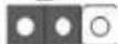
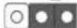
2.5 Jumpers Setup
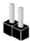
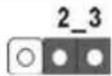
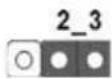
The illustration shows how jumpers are setup. When the jumper cap is placed on pins, the jumper is "Short". If no jumper cap is placed on pins, the jumper is "Open". The illustration shows a 3-pin jumper whose pin1 and pin2 are "Short" when jumper cap is placed on these 2 pins.

Short
Open

Jumper Setting Description
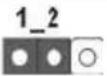
Clear CMOS Jumper
(CLRCMOS1)
(see p.2, No. 9)
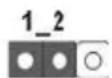
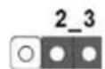
Clear CMOSDefault
Note: CLRCMOS1 allows you to clear the data in CMOS. To clear and reset the system parameters to default setup, please turn off the computer and unplug the power cord from the power supply. After waiting for 15 seconds, use a jumper cap to short pin2 and pin3 on CLRCMOS1 for 5 seconds. However, please do not clear the CMOS right after you update the BIOS. If you need to clear the CMOS when you just finish updating the BIOS, you must boot up the system first, and then shut it down before you do the clear-CMOS action. Please be noted that the password, date, time, user default profile, 1394 GUID and MAC address will be cleared only if the CMOS battery is removed.

If you clear the CMOS, the case open may be detected. Please adjust the BIOS option "Clear Status" to clear the record of previous chassis intrusion status.
2.6 Onboard Headers and Connectors

Onboard headers and connectors are NOT jumpers. Do NOT place jumper caps over these headers and connectors. Placing jumper caps over the headers and connectors will cause permanent damage of the motherboard!
Serial ATA3 Connectors These six Serial ATA3
(SATA3_1: see p.2, No. 14) (SATA3) connectors support (SATA3_2: see p.2, No. 15) SATA data cables for internal storage devices. The current (SATA3_3: see p.2, No. 13) SATA3 Interface allows up to (SATA3_4: see p.2, No. 12) 6.0 Gb/s data transfer rate. (SATA3_5: see p.2, No. 11)
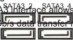
SATA3_1 SATA3_3
USB 2.0 Headers Besides four default USB 2.0
(9-pin USB_5_6) ports on the I/O panel, there (see p.2 No. 19) are three USB 2.0 headers on this motherboard. Each USB 2.0 header can support two USB
(9-pin USB_7_8) 2.0 ports. (see p.2 No. 20)
(9-pin USB_9_10) (see p.2 No. 21)

text_image
USB_PWR P-8 R+8 GND DUMMY 1 GND P+7 P-7 USB_PWR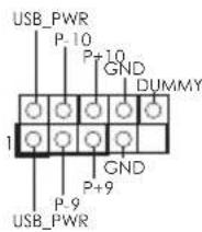
text_image
USB_PWR P-10 P+10 GND DUMMY 1 GND P+9 P-9 USB_PWRUSB 3.0 Header Besides two default USB 3.0
(19-pin USB3_3_4) ports on the V/O panel, there is (see p.2, No. 8) one USB 3.0 header on this motherboard. This USB 3.0 header can support two USB 3.0 ports.
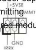
Infrared Module Header This header supports an
(5-pin IR1) optional wireless transmitting (see p.2 No. 25) and receiving infrared module.
Front Panel Audio Header This is an interface for the front
(9-pin HD_AUDIO1) panel audio cable that allows OUT RET
(see p.2 No. 26) convenient connection and
control of audio devices.


-
High Definition Audio supports Jack Sensing, but the panel wire on the chassis must support HDA to function correctly. Please follow the instruction in our manual and chassis manual to install your system.
-
If you use AC'97 audio panel, please install it to the front panel audio header as below:
A. Connect Mic_IN (MIC) to MIC2_L.
B. Connect Audio_R (RIN) to OUT2_R and Audio_L (LIN) to OUT2_L.
C. Connect Ground (GND) to Ground (GND).
D. MIC_RET and OUT_RET are for HD audio panel only. You don't need to connect them for AC'97 audio panel.
E. To activate the front mic.
For Windows ^® 8 / 8 64-bit / 7 / 7 64-bit 64-bit OS:
Go to the "FrontMic" Tab in the Realtek Control panel. Adjust "Recording Volume".
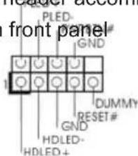
System Panel Header This header accommodates
(9-pin PANEL1) several system front panel
(see p.2 No. 16) functions.
text_image
PLED- GND# 1 DUMMY RESET# GND HDLED- HDLED+ front panel
Connect the power switch, reset switch and system status indicator on the chassis to this header according to the pin assignments below.
Note the positive and negative pins before connecting the cables.
PWRBTN (Power Switch):
Connect to the power switch on the chassis front panel. You may configure the way to turn off your system using the power switch.
RESET (Reset Switch):
Connect to the reset switch on the chassis front panel. Press the reset switch to restart the computer if the computer freezes and fails to perform a normal restart.
PLED (System Power LED):
Connect to the power status indicator on the chassis front panel. The LED is on when the system is operating. The LED keeps blinking when the sys-tem is in S1 sleep state. The LED is off when the system is in S3/S4 sleep state or powered off (S5).
HDLED (Hard Drive Activity LED):
Connect to the hard drive activity LED on the chassis front panel. The LED is on when the hard drive is reading or writing data.
The front panel design may differ by chassis. A front panel module mainly consists of power switch, reset switch, power LED, hard drive activity LED, speaker and etc. When connecting your chassis front panel module to this header, make sure the wire assignments and the pin assignments are matched correctly.
Chassis Speaker Header Please connect the chassis
(4-pin SPEAKER 1) speaker to this header
(see p.2 No. 18) +5V DUMM
Power LED Header Please connect the chassis
(3-pin PLED1) power LED to this header to
(see p.2 No. 17) indicate system power status.
The LED is on when the system
is operating. The LED keeps
blinking in S1 state. The LED is
off in S3/S4 state or S5 state
(power off).
Chassis and Power Fan Connectors Please connect the fan cables
(4-pin CHA_FAN1) to the fan connectors and
(see p.2 No. 28) match the black wire to the
speed can be controlled through
UEFI or A-Tuning.
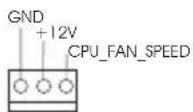
CPU Fan Connectors Please connect the CPU fan
(4-pin CPU_FAN1) cable to the connector and
(see p.2 No. 3) match the black wire to the
ground pin.


Though this motherboard provides 4-Pin CPU fan (Quiet Fan) support, the 3-Pin
CPU fan still can work successfully even without the fan speed control function.
If you plan to connect the 3-Pin CPU fan to the CPU fan connector on this
motherboard, please connect it to Pin 1-3.
Pin 1-3 Connected

3-Pin Fan Installation
(3-pin CPU_FAN2)
(see p.2 No. 4)
ATX Power Connector Please connect an ATX power
(24-pin ATXPWR1) supply to this connector.
(see p.2 No. 7)

Though this motherboard provides 24-pin ATX power connector, it can still work if you adopt a traditional 20-pin ATX power supply.
To use the 20-pin ATX power supply, please plug your power supply along with Pin 1 and Pin 13.
20-Pin ATX Power Supply Installation

text_image
12 24 13 1ATX 12V Power Connector Please connect an ATX 12V
(8-pin ATX12V1) power supply to this connector.
(see p.2 No. 2)
1 5

Though this motherboard provides 8-pin ATX 12V power connector, it can still work
if you adopt a traditional 4-pin ATX 12V power supply. To use the 4-pin ATX power supply, please plug your power supply along with Pin 1 and Pin 5.
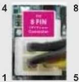
4-Pin ATX 12V Power Supply Installation
Serial port Header
(9-pin COM1)
(see p.2 No. 24)
This COM1 header supports a

text_image
DDIR#1 DDS#1 CCIS# I RRI# RRIS# GND TTXD1 DDCD#1serial port module.
Chassis Intrusion Header This motherboard supports
(2-pin CI1) CASE OPEN detection feature
(see p.2, No. 27) that detects if the chassis cover
has been removed. This feature
requires a chassis with chassis
intrusion detection design.
Print Port Header This is an interface for print
(25-pin LPT1) port cable that allows
(see p.2, No. 23) conveni
devices.
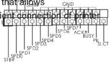
text_image
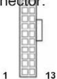
that allows ent connection of printer GND SPD7 SPD6 SPD5 SPD4 SPD3 SPD2 SPD1 SPD0 SPD#1 SPD#2 SPD#3 SPD4# SPD7#AC# BUSY SLCTTPM Header This connector supports
(17-pin TPMS1) Trusted Platform Module (TPM)
(see p.2, No. 22) system, which can securely
store keys, digital certificates,
passwords, and data. A TPM
system also helps enhance
network security, protects
digital identities, and ensures
platform integrity.
3. BIOS Information
The Flash Memory on the motherboard stores BIOS Setup Utility. When you start up the computer, please press during the Power-On-Self-Test (POST) to enter BIOS Setup utility; otherwise, POST continues with its test routines. If you wish to enter BIOS Setup after POST, please restart the system by pressing
4. Software Support CD information
This motherboard supports various Microsoft ^® Windows ^® operating systems: 8.1 32-bit / 8.1 64-bit / 8 32-bit / 8 64-bit / 7 32-bit / 7 64-bit. The Support CD that came with the motherboard contains necessary drivers and useful utilities that will enhance motherboard features. To begin using the Support CD, insert the CD into your CD-ROM drive. It will display the Main Menu automatically if “AUTORUN” is enabled in your computer. If the Main Menu does not appear automatically, locate and double-click on the file “ASRSETUP.EXE” from the BIN folder in the Support CD to display the menus.
1. Einführung
www.asrock.com/support/index.asp
1.1 Kartoninhalt
ASRock FM2A75M Pro4+ Motherboard (Micro ATX-Formfaktor)
ASRock FM2A75M Pro4+ Support-CD
Zwei Serial ATA (SATA) -Datenkabel (optional)
Ein I/O Shield

ASRock erinnert...
(CLRCMOS1, 3-Pin jumper)
(siehe S.2, No. 9)

Default-
Einstellung

CMOS
löschen
www.asrock.com/support/index.asp
Scheda madre ASRock FM2A75M Pro4+ (Micro ATX Form Factor)
(4-pin CHA_FAN1) corrispondenti-connettori
natural_image
Close-up of a multicolored electrical connector with wires, labeled 1, 12, 24, and 13 (no readable text or symbols beyond labels)(CLRCMOS1, jumper de 3 pins)
(ver p.2, No. 9)
Valor predeterminado
(CLRCMOS1, jumper de 3 pinos)
(CLRCMOS1, 3-pinli jumper)
(bkz. S.2 No. 9)

Clear CMOSDefault
www.asrock.com/support/index.asp
1.1 패키지 내용
natural_image
Close-up of a colorful electronic component with labeled pins (1, 12, 13, 24), no readable text or symbols beyond labelswww.asrock.com/support/index.asp
1.1 包装盒内物品
www.asrock.com/support/index.asp
1.1 白装盒队物品
natural_image
Close-up of a colorful electrical connector with labeled pins (1, 12, 24, 13), no readable text or symbols beyond labels20-Pin ATX 電源安裝說明
1 13
Support CD FM2A75M Pro4+ ASRock
2 x Kabel satu serial Data ATA (SATA) (bebas-pilih)
1 x Satu Pelindung I/O

ASRock Mengingatkan...
If you need to contact ASRock or want to know more about ASRock, you're welcome to visit ASRock's website at http://www.asrock.com; or you may contact your dealer for further information. For technical questions, please submit a support request form at http://www.asrock.com/support/tsd.asp
ASRock Incorporation
2F., No.37, Sec. 2, Jhongyang S. Rd., Beitou District,
Taipei City 112, Taiwan (R.O.C.)
ASRock EUROPE B.V.
Bijsterhuizen 3151
6604 LV Wijchen
The Netherlands
Phone: +31-24-345-44-33
Fax: +31-24-345-44-38
ASRock America, Inc.
13848 Magnolia Ave, Chino, CA91710
U.S.A.
Phone: +1-909-590-8308
Fax: +1-909-590-1026