SL300 - Portable radio MOTOROLA - Free user manual and instructions
Find the device manual for free SL300 MOTOROLA in PDF.
| Product Type | Portable radio |
| Brand | Motorola |
| Model | SL300 |
| Power Supply | Rechargeable lithium-ion battery 2300 mAh (PMNN4468_) |
| Battery Life | Full charge recommended 14-16 hours before first use |
| Ingress Protection Rating | IP54 (resistant to splashes and dust) |
| Operating Modes | Analog and conventional digital |
| Channels | Up to 99 channels (model with display) / 2 channels (no display) |
| Zones | Up to 2 zones (model with display) / 1 zone (no display) |
| Call Types | Group, private, broadcast, selective, all call, no destination, OVCM |
| Emergency Function | Emergency alarm with/without voice call, silent, reset |
| Advanced Features | Scanning, monitoring, text messaging, VOX, voice announcement, analog scrambling, privacy |
| Connectivity | Micro-USB port for charging, 12-pin accessory connector |
| Antenna | Removable, multiple models available depending on frequency (VHF/UHF) |
| Included Accessories | Battery, antenna, charger (depending on kit) |
| Maintenance and Cleaning | Clean with a soft cloth and a solution of water and mild detergent; do not use high-pressure jets |
| Safety | Emergency alarm, lone worker, low battery and battery fault warnings |
| Warranty | 2 years for the radio, 1 year for accessories (battery 12 months) |
| Recommended Charging Temperature | Room temperature |
| Country of Origin | Manufactured by Motorola Solutions, Inc. (USA) |
Frequently Asked Questions - SL300 MOTOROLA
User questions about SL300 MOTOROLA
0 question about this device. Answer the ones you know or ask your own.
Ask a new question about this device
Download the instructions for your Portable radio in PDF format for free! Find your manual SL300 - MOTOROLA and take your electronic device back in hand. On this page are published all the documents necessary for the use of your device. SL300 by MOTOROLA.
USER MANUAL SL300 MOTOROLA
SL300 Portable Radio User Guide
Contents
Legal and Support. 5
Intellectual Property and Regulatory Notices. 5
Legal and Compliance Statements. 6
Supplier's Declaration of Conformity 6
Important Safety Information. 7
Notice to Users (FCC) 7
Notice to Users (Industry Canada) 7
Warranty and Service Support. 7
Batteries and Chargers Warranty. 7
The Workmanship Warranty. 7
The Capacity Warranty. 7
Limited Warranty. 8
MOTOROLA SOLUTIONS COMMUNICATION PRODUCTS 8
I. WHAT THIS WARRANTY COVERS AND FOR HOW LONG: 8
II. GENERAL PROVISIONS 8
III. STATE LAW RIGHTS: 9
IV. HOW TO GET WARRANTY SERVICE 9
V. WHAT THIS WARRANTY DOES NOT COVER 9
VI. PATENT AND SOFTWARE PROVISIONS 9
VII. GOVERNING LAW 10
Chapter 1: Read Me First. 11
1.1 Software Version 12
Chapter 2: Introduction. 13
Chapter 3: Radio Care. 14
Chapter 4: Getting Started. 15
4.1 Charging the Battery 15
4.2 Attaching the Battery 15
4.3 Removing the Battery 16
4.4 Attaching the Antenna 16
4.5 Removing the Antenna 16
4.6 Attaching the Earpiece or Audio Accessory 17
4.7 Turning Radio On or Off 17
4.8 Adjusting the Volume 17
Chapter 5: Radio Overview 18
5.1 Programmable Buttons 20
5.2 LED Indications 21
Chapter 6: System Overview. 23
6.1 Conventional Analog and Digital Modes 23
Chapter 7: Zone and Channel Selections 24
7.1 Selecting Zones 24
7.2 Selecting a Channel 24
Chapter 8: Site Overview 25
8.1Turning the Site Lock On. 25
8.2Turning the Site Lock Off 25
Chapter 9: Types of Radio Calls 26
9.1 Making Calls on the Radio 26
9.2 Receiving and Responding to Calls on the Radio 27
Chapter 10: Advanced Features 28
10.1 Auto-Range Transponder System 28
10.2 Call Alert Operation 28
10.2.1 Making Call Alerts 28
10.2.2 Responding to Call Alerts 28
10.3 Call Indicator Settings 29
10.3.1 Alarm Tone Volume Escalation 29
10.4 Emergency Operation 29
10.4.1 Sending Emergency Alarms 30
10.4.2 Sending Emergency Alarms with Call 30
10.4.3 Sending Emergency Alarms with Voice to Follow 31
10.4.4 Reinitiating the Emergency Mode 31
10.4.5 Exiting the Emergency Mode 31
10.5 Lone Worker 32
10.6 Monitor Feature 32
10.6.1 Monitoring Channels 32
10.6.2 Permanent Monitor 32
10.6.2.1 Setting the Permanent Monitor 32
10.7 Scan 33
10.7.1Turning Scan On or Off 33
10.7.2 Scan Talkback 34
10.7.3 Nuisance Channels 34
10.7.3.1 Deleting Nuisance Channels 34
10.7.3.2 Restoring Nuisance Channels 34
10.7.4Vote Scan. 35
10.7.5 Scan Lists 35
10.8 Text Messaging 35
10.8.1 Sending Quick Text Message 35
Chapter 11: Utilities 36
11.1 Analog Scrambling 36
11.2 Talkaround 36
11.2.1 Toggling Between Repeater and Talkaround Mode 36
11.3 Setting Radio Tones and Alerts 36
11.4 Setting Power Levels 37
11.5 Setting Squelch Levels 37
11.6 Viewing RSSI Values 37
11.7 Voice Operating Transmission 37
11.7.1 Setting the Voice Operating Transmission 37
11.8 Voice Announcement 38
11.8.1 Setting the Voice Announcement 38
11.9 Setting the Trill Enhancement 38
11.10 Privacy 38
11.10.1 Setting Privacy 39
11.10.2 Privacy-Enabled Calls 39
Chapter 12: Authorized Accessories List. 40
Legal and Support
Intellectual Property and Regulatory Notices
Copyrights
The Motorola Solutions products described in this document may include copyrighted Motorola Solutions computer programs. Laws in the United States and other countries preserve for Motorola Solutions certain exclusive rights for copyrighted computer programs. Accordingly, any copyrighted Motorola Solutions computer programs contained in the Motorola Solutions products described in this document may not be copied or reproduced in any manner without the express written permission of Motorola Solutions.
No part of this document may be reproduced, transmitted, stored in a retrieval system, or translated into any language or computer language, in any form or by any means, without the prior written permission of Motorola Solutions, Inc.
Trademarks
MOTOROLA, MOTO, MOTOROLA SOLUTIONS, and the Stylized M Logo are trademarks or registered trademarks of Motorola Trademark Holdings, LLC and are used under license. All other trademarks are the property of their respective owners.
License Rights
The purchase of Motorola Solutions products shall not be deemed to grant either directly or by implication, estoppel or otherwise, any license under the copyrights, patents or patent applications of Motorola Solutions, except for the normal non-exclusive, royalty-free license to use that arises by operation of law in the sale of a product.
Open Source Content
This product may contain Open Source software used under license. Refer to the product installation media for full Open Source Legal Notices and Attribution content.
European Union (EU) and United Kingdom (UK) Waste of Electrical and Electronic Equipment (WEEE) Directive

The European Union's WEEE directive and the UK's WEEE regulation require that products sold into EU countries and the UK must have the crossed-out wheelie bin label on the product (or the package in some cases). As defined by the WEEE directive, this crossed-out wheelie bin label means that customers and end-users in EU and UK countries should not dispose of electronic and electrical equipment or accessories in household waste.
Customers or end-users in EU and UK countries should contact their local equipment supplier representative or service centre for information about the waste collection system in their country.
Disclaimer
Please note that certain features, facilities, and capabilities described in this document may not be applicable to or licensed for use on a specific system, or may be dependent upon the characteristics of a specific mobile subscriber unit or configuration of certain parameters. Please refer to your Motorola Solutions contact for further information.
© 2023 Motorola Solutions, Inc. All Rights Reserved
Legal and Compliance Statements
Supplier's Declaration of Conformity
Supplier's Declaration of Conformity
Per FCC CFR 47 Part 2 Section 2.1077(a)

Responsible Party
Name: Motorola Solutions, Inc.
Address: 2000 Progress Pkwy, Schaumburg, IL. 60196
Phone Number: 1-800-927-2744
Hereby declares that the product:
Model Name: SL300
conforms to the following regulations:
FCC Part 15, subpart B, section 15.107(a), 15.107(d), and section 15.109(a)
Class B Digital Device
As a personal computer peripheral, this device complies with Part 15 of the FCC Rules. Operation is subject to the following two conditions:
1 This device may not cause harmful interference, and
2 This device must accept any interference received, including interference that may cause undesired operation.

NOTE:
This equipment has been tested and found to comply with the limits for a Class B digital device, pursuant to part 15 of the FCC Rules. These limits are designed to provide reasonable protection against harmful interference in a residential installation. This equipment generates, uses and can radiate radio frequency energy and, if not installed and used in accordance with the instructions, may cause harmful interference to radio communications. However, there is no guarantee that interference will not occur in a particular installation.
If this equipment does cause harmful interference to radio or television reception, which can be determined by turning the equipment off and on, the user is encouraged to try to correct the interference by one or more of the following measures:
Reorient or relocate the receiving antenna.
- Increase the separation between the equipment and receiver.
- Connect the equipment into an outlet on a circuit different from that to which the receiver is connected.
- Consult the dealer or an experienced radio or TV technician for help.
Important Safety Information

CAUTION:
This radio is restricted to Occupational use only. Before using the radio, read the RF Energy Exposure and Product Safety Guide that comes with the radio. This guide contains operating instructions for safe usage, RF energy awareness, and control for compliance with applicable standards and regulations.
Any modification to this device, not expressly authorized by Motorola Solutions, may void the user's authority to operate this device.
Under Industry Canada regulations, this radio transmitter may only operate using an antenna of a type and maximum (or lesser) gain approved for the transmitter by Industry Canada. To reduce potential radio interference to other users, the antenna type and its gain should be so chosen that the equivalent isotropically radiated power (e.i.r.p.) is not more than that necessary for successful communication.
This radio transmitter has been approved by Industry Canada to operate with Motorola Solutions-approved antenna with the maximum permissible gain and required antenna impedance for each antenna type indicated. Antenna types not included in this list, having a gain greater than the maximum gain indicated for that type, are strictly prohibited for use with this device.
Notice to Users (FCC)
This device complies with Part 15 of the FCC rules per the following conditions:
- This device may not cause harmful interference.
This device must accept any interference received, including interference that may cause undesired operation. - Changes or modifications made to this device, not expressly approved by Motorola Solutions, could void the authority of the user to operate this equipment.
Notice to Users (Industry Canada)
The operation of your Motorola Solutions radio is subject to the Radiocommunications Act and must comply with rules and regulations of the Federal Government's department of Industry Canada. Industry Canada requires that all operators using Private Land Mobile frequencies obtain a radio license before operating their equipment.
Warranty and Service Support
Batteries and Chargers Warranty
The Workmanship Warranty
The workmanship warranty guarantees against defects in workmanship under normal use and service.
| SL Series Batteries | 12 Months |
| Chargers (Single-Unit and Multi-Unit, Non-Display) | 12 Months |
The Capacity Warranty
The capacity warranty guarantees 80% of the rated capacity for the warranty duration.
| Lithium-Ion (Li-Ion) Batteries | 12 Months |
Limited Warranty
MOTOROLA SOLUTIONS COMMUNICATION PRODUCTS
I. WHAT THIS WARRANTY COVERS AND FOR HOW LONG:
Motorola Solutions, Inc. ("Motorola Solutions") warrants the Motorola Solutions manufactured Communication Products listed below ("Product") against defects in material and workmanship under normal use and service for a period of time from the date of purchase as scheduled below:
| Portable Radios | Two (2) Years |
| Product Accessories | One (1) Year |
Motorola Solutions, at its option, will at no charge either repair the Product (with new or reconditioned parts), replace it (with a new or reconditioned Product), or refund the purchase price of the Product during the warranty period provided it is returned in accordance with the terms of this warranty. Replaced parts or boards are warranted for the balance of the original applicable warranty period. All replaced parts of Product shall become the property of Motorola Solutions.
This express limited warranty is extended by Motorola Solutions to the original end user purchaser only and is not assignable or transferable to any other party. This is the complete warranty for the Product manufactured by Motorola Solutions. Motorola Solutions assumes no obligations or liability for additions or modifications to this warranty unless made in writing and signed by an officer of Motorola Solutions.
Unless made in a separate agreement between Motorola Solutions and the original end user purchaser, Motorola Solutions does not warrant the installation, maintenance or service of the Product.
Motorola Solutions cannot be responsible in any way for any ancillary equipment not furnished by Motorola Solutions which is attached to or used in connection with the Product, or for operation of the Product with any ancillary equipment, and all such equipment is expressly excluded from this warranty. Because each system which may use the Product is unique, Motorola Solutions disclaims liability for range, coverage, or operation of the system as a whole under this warranty.
II. GENERAL PROVISIONS
This warranty sets forth the full extent of Motorola Solutions responsibilities regarding the Product. Repair, replacement or refund of the purchase price, at Motorola Solutions option, is the exclusive remedy. THIS WARRANTY IS GIVEN IN LIEU OF ALL OTHER EXPRESS WARRANTYES. IMPLIED WARRANTYES, INCLUDING WITHOUT LIMITATION, IMPLIED WARRANTYES OF MERCHANTABILITY AND FITNESS FOR A PARTICULAR PURPOSE, ARE LIMITED TO THE DURATION OF THIS LIMITED WARRANTY. IN NO EVENT SHALL MOTOROLA SOLUTIONS BE LIABLE FOR DAMAGES IN EXCESS OF THE PURCHASE PRICE OF THE PRODUCT, FOR ANY LOSS OF USE, LOSS OF TIME, INCONVENIENCE, COMMERCIAL LOSS, LOST PROFITS OR SAVINGS OR OTHER INCIDENTAL, SPECIAL OR CONSEQUENTIAL DAMAGES ARISING OUT OF THE USE OR INABILITY TO USE SUCH PRODUCT, TO THE FULL EXTENT SUCH MAY BE DISCLAIMED BY LAW.
III. STATE LAW RIGHTS:
SOME STATES DO NOT ALLOW THE EXCLUSION OR LIMITATION OF INCIDENTAL OR CONSEQUENTIAL DAMAGES OR LIMITATION ON HOW LONG AN IMPLIED WARRANTY LASTS, SO THE ABOVE LIMITATION OR EXCLUSIONS MAY NOT APPLY.
This warranty gives specific legal rights, and there may be other rights which may vary from state to state.
IV. HOW TO GET WARRANTY SERVICE
You must provide proof of purchase (bearing the date of purchase and Product item serial number) in order to receive warranty service and, also, deliver or send the Product item, transportation and insurance prepaid, to an authorized warranty service location. Warranty service will be provided by Motorola Solutions through one of its authorized warranty service locations. If you first contact the company which sold you the Product (for example, dealer or communication service provider), it can facilitate your obtaining warranty service. You can also call Motorola Solutions at 1-800-927-2744.
V. WHAT THIS WARRANTY DOES NOT COVER
1 Defects or damage resulting from use of the Product in other than its normal and customary manner.
2 Defects or damage from misuse, accident, water, or neglect.
3 Defects or damage from improper testing, operation, maintenance, installation, alteration, modification, or adjustment.
4 Breakage or damage to antennas unless caused directly by defects in material workmanship.
5 A Product subjected to unauthorized Product modifications, disassembles or repairs (including, without limitation, the addition to the Product of non-Motorola Solutions supplied equipment) which adversely affect performance of the Product or interfere with Motorola Solutions normal warranty inspection and testing of the Product to verify any warranty claim.
6 Product which has had the serial number removed or made illegible.
7 Rechargeable batteries if:
- any of the seals on the battery enclosure of cells are broken or show evidence of tampering.
- the damage or defect is caused by charging or using the battery in equipment or service other than the Product for which it is specified.
8 Freight costs to the repair depot.
9 A Product which, due to illegal or unauthorized alteration of the software/firmware in the Product, does not function in accordance with Motorola Solutions published specifications or the FCC certification labeling in effect for the Product at the time the Product was initially distributed from Motorola Solutions.
10 Scratches or other cosmetic damage to Product surfaces that does not affect the operation of the Product.
11 Normal and customary wear and tear.
VI. PATENT AND SOFTWARE PROVISIONS
Motorola Solutions will defend, at its own expense, any suit brought against the end user purchaser to the extent that it is based on a claim that the Product or parts infringe a United States patent, and Motorola Solutions will pay those costs and damages finally awarded against the end user purchaser in any such suit which are attributable to any such claim, but such defense and payments are conditioned on the following:
1 Motorola Solutions will be notified promptly in writing by such purchaser of any notice of such claim,
2 Motorola Solutions will have sole control of the defense of such suit and all negotiations for its settlement or compromise, and
3 Should the Product or parts become, or in Motorola Solutions opinion be likely to become, the subject of a claim of infringement of a United States patent, that such purchaser will permit Motorola Solutions, at its option and expense, either to procure for such purchaser the right to continue using the Product or parts or to replace or modify the same so that it becomes non-infringing or to grant such purchaser a credit for the Product or parts as depreciated and accept its return. The depreciation will be an equal amount per year over the lifetime of the Product or parts as established by Motorola Solutions.
Motorola Solutions will have no liability with respect to any claim of patent infringement which is based upon the combination of the Product or parts furnished hereunder with software, apparatus or devices not furnished by Motorola Solutions, nor will Motorola Solutions have any liability for the use of ancillary equipment or software not furnished by Motorola Solutions which is attached to or used in connection with the Product. The foregoing states the entire liability of Motorola Solutions with respect to infringement of patents by the Product or any parts thereof.
Laws in the United States and other countries preserve for Motorola Solutions certain exclusive rights for copyrighted Motorola Solutions software such as the exclusive rights to reproduce in copies and distribute copies of such Motorola Solutions software. Motorola Solutions software may be used in only the Product in which the software was originally embodied and such software in such Product may not be replaced, copied, distributed, modified in any way, or used to produce any derivative thereof. No other use including, without limitation, alteration, modification, reproduction, distribution, or reverse engineering of such Motorola Solutions software or exercise of rights in such Motorola Solutions software is permitted. No license is granted by implication, estoppel or otherwise under Motorola Solutions patent rights or copyrights.
VII. GOVERNING LAW
This Warranty is governed by the laws of the State of Illinois, U.S.A.
Chapter 1
Read Me First
This user guide covers the basic operations of the radio models offered in your region.
Notations Used in This Manual
Throughout the text in this publication, you notice the use of Warning, Caution, and Notice. These notations are used to emphasize that safety hazards exist, and the care that must be taken or observed.

WARNING: An operational procedure, practice, or condition, and so on, which may result in injury or death if not carefully observed.

CAUTION: An operational procedure, practice, or condition, and so on, which may result in damage to the equipment if not carefully observed.

NOTE: An operational procedure, practice, or condition, and so on, which is essential to emphasize.
Special Notations
The following special notations are used throughout the text to highlight certain information or items:
Table 1: Special Notations
| Example | Description |
| Menu key or PTT button | Bold words indicate a name of a key, button, or soft menu item. |
| Your radio shows Bluetooth On. | Typewriter words indicate the MMI strings or messages displayed on your radio. |
| <required ID> | The courier, bold, italic, and angle brackets indicate user input. |
| Setup→Tone→All Tones | Bold words with the arrow in between indicate the navigation structure in the menu items. |
Feature and Service Availability
Your dealer or administrator may have customized your radio for your specific needs.

NOTE:
- Not all features in the manual are available in your radio. Contact your dealer or administrator for more information.
You can consult your dealer or system administrator about the following:
What are the functions of each button?
- Which optional accessories may suit your needs?
What are the best radio usage practices for effective communication?
- What maintenance procedures promote longer radio life?
1.1
Software Version
All the features described in the following sections are supported by the software version R01.20.01.0000 or later.
Contact your dealer or administrator for more information.
Chapter 2
Introduction
This user guide is written as per the highest tier model offered to the region.
The following table describes ways to access features for different radio models. You receive different indications depending on the radio model.
Table 2: The Feature Access and Indications of Different Radio Model
| Display | Non-Display | |
| Radio Model | Figure 1: SL300 | Figure 2: SL300 |
| MOTOROLA CH2 | MOTOROLA CH2 | |
| Feature Access | · Menu · Programmable Button | Programmable Button |
| Feature Indication | · Tone · LED indicator · Display · Voice Announcement or Text-to-Speech | · Tone · LED indicator · Voice Announcement or Text-to-Speech |

NOTE: To understand which feature is available with the Programmable Button, you can refer to the Programmable Buttons on page 20 topic.
Chapter 3
Radio Care
This section describes the basic handling precaution of the radio.
Table 3: IP Specification
| IP Specification | Description |
| IP54 | Allows your radio to withstand adverse field conditions such as being exposed to water splashed from all directions or dust protected for 2–8 hours. |

CAUTION: Do not disassemble your radio. This could damage radio seals and result in leak paths into the radio. Radio maintenance should only be done in service depot that is equipped to test and replace the seal on the radio.
- Keep your radio clean and exposure to water should be avoided to help ensure proper functionality and performance.
- To clean the exterior surfaces of the radio, use a diluted solution of mild dishwashing detergent and fresh water (for example, one teaspoon of detergent to one gallon of water).
- These surfaces should be cleaned whenever a periodic visual inspection reveals the presence of smudges, grease, and/or grime.

CAUTION: The effects of certain chemicals and their vapors can have harmful results on certain plastics. Avoid using aerosol sprays, tuner cleaners, and other chemicals.
- When cleaning your radio, do not use a high-pressure jet spray on radio as this may cause water to leak into your radio.
Chapter 4
Getting Started
This chapter provides instructions on how to prepare your radio for use.
4.1
Charging the Battery
Your radio is powered by a Nickel Metal-Hydride (NiMH) or Lithium-Ion (Li-Ion) battery.
Prerequisites: Turn off your radio when charging.
Procedure:
- Charge your battery only in non-hazardous areas. After battery is charged, allow your radio to rest for at least 3 minutes.
- To comply with warranty terms and avoid damage, charge the battery using a Motorola Solutions authorized charger as described in the charger user guide.
- Charge a new battery 14 to 16 hours before initial use for best performance.
Batteries charge best at room temperature.

NOTE:
You may charge your battery by connecting the USB charger to a nearby and easily accessible wall power outlet.
4.2
Attaching the Battery
Procedure:
1 Fit the battery into the battery slot of the radio.
2 Place the back cover into position and press until it snaps into place.
3 Slide the battery latch into lock position.
Postrequisites:

NOTE:
If the radio is attached with the wrong battery, your radio shows the following indications:
A low pitched warning tone sounds.
The red LED blinks.
- The display shows Wrong Battery
- Voice Announcement or Text-to-Speech sounds "Wrong Battery" if the Voice Announcement or Text-to-Speech is loaded by using CPS.
If the radio is attached with an unsupported battery, your radio shows the following indications:
- An alert tone sounds.
The display shows Unknown Battery. - Battery icon is disabled.
The certification of the radio is voided if you attach a UL battery to an FM approved radio or vice versa.
If your radio is attached with an unsupported or wrong battery, immediately swap with the correct battery.
4.3
Removing the Battery
Prerequisites: Ensure that your radio is turned off.
Procedure:
1 Move the battery latch into unlock position.
2 Remove the back cover.
3 Take the battery out from the battery slot.
4.4
Attaching the Antenna
Procedure:
1 Set the antenna in the receptacle.
2 Turn the antenna clockwise.

NOTE: Fastening the antenna blocks water and dust from entering the radio.

CAUTION: To prevent damages, replace the faulty antenna with only MOTOTRBO antennas.
4.5
Removing the Antenna
Procedure:
1 Turn the antenna counterclockwise.
2 Remove the antenna from the receptacle.
4.6
Attaching the Earpiece or Audio Accessory
The audio accessory connector is located on the right side of the radio. Follow the procedure to attach accessories to your radio.
Procedure:
1 Lift the flap of the audio jack cover.
2 Align the indicators on both the connector and housing, then push until it fits in properly.
4.7
Turning Radio On or Off
Procedure:
Press and hold the Power/Information button.
If turning radio on successful, your radio shows the following indications:
A tone sounds.

NOTE: If the Tones/Alerts function is disabled, there is no tone upon powering up.
The green LED illuminates.
- The display shows power-on animation.
The Home screen lights up.
If turning radio off successfully, your radio shows the following indications:
A tone sounds.
The Home screen turns off.
Postrequisites: If your radio does not power up, check your battery. Make sure that the battery is charged and properly attached. Contact your dealer if your radio still does not power up.
4.8
Adjusting the Volume
Procedure:
1 Perform one of the following actions:
To increase the volume, press the Volume Up button.
To decrease the volume, press the Volume Down button.

NOTE: Your radio can be programmed to have a minimum volume offset where the volume level cannot be lowered past the programmed minimum volume.
Chapter 5
Radio Overview
Radio overview explains the buttons, icons, and LED indications of your radio.
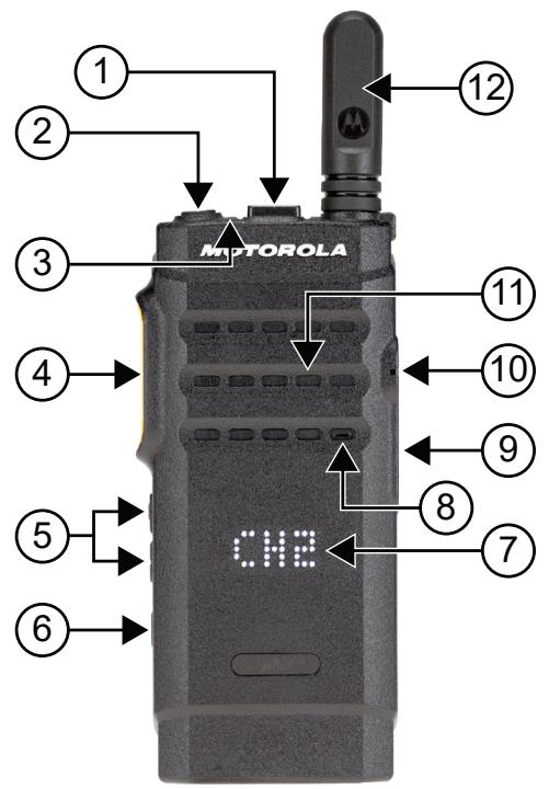
Figure 3: Display Model
Table 4: Checkout Legend
| Label | Item | Description |
| 1 | Channel Rocker | To select channel. |
| 2 | Power/Information button | To turn your radio on or off. |
| When the radio is turned on, you can perform the following actions: • To check the battery strength. • To check the Received Signal Strength Indicator (RSSI). • To check radio name by pressing the button twice. | ||
| 3 | LED Indicator | The red, green, and amber light-emitting diodes indicate operating status. |
| 4 | Push-To-Talk (PTT) button | To execute voice operations (for example, Group Call and Private Call). |
| 5 | Volume Up or Down button | To adjust volume. |
| 6 | Side button | This button is field programmable using the Customer Programming Software (CPS). |
| 7 | Display | To provide visual information about many radio features. |
| 8 | Microphone | Allows the voice to be sent when PTT or voice operations are activated. |
| 9 | Micro-USB Connector | To charge radio. |
| 10 | Accessory Connector | Interface point for all accessories to be used with the radio. It has twelve points to which specific accessories will connect and be activated. |
| 11 | Speaker | Outputs all tones and audio that are generated by the radio (for example, features like keypad tones and voice audio). |
| 12 | Antenna | Provides the needed RF amplification when transmitting or receiving. |
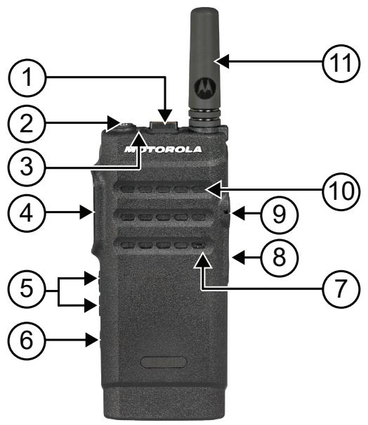
Figure 4: Non-Display Model
Table 5: Checkout Legend
| Label | Item | Description |
| 1 | Channel Rocker | To select channel. |
| 2 | Power/Information button | To turn your radio on or off. |
| When the radio is turned on, you can perform the following actions: | ||
| To check the battery strength. | ||
| To check the Received Signal Strength Indicator (RSSI). | ||
| To check radio name by pressing the button twice. | ||
| 3 | LED Indicator | The red, green, and amber light-emitting diodes indicate operating status. |
| 4 | Push-To-Talk (PTT) button | To execute voice operations (for example, Group Call and Private Call). |
| 5 | Volume Up or Down button | To adjust volume. |
| 6 | Side button | This button is field programmable using the Customer Programming Software (CPS). |
| 7 | Microphone | Allows the voice to be sent when PTT or voice operations are activated. |
| 8 | Micro-USB Connector | To charge radio. |
| 9 | Accessory Connector | Interface point for all accessories to be used with the radio. It has twelve points to which specific accessories will connect and be activated. |
| 10 | Speaker | Outputs all tones and audio that are generated by the radio (for example, features like keyboard tones and voice audio). |
| 11 | Antenna | Provides the needed RF amplification when transmitting or receiving. |
5.1
Programmable Buttons
You can program the programmable buttons as shortcuts to the following radio functions through programming software.

NOTE: Contact your dealer for more information.
Table 6: Assignable Radio Functions
| Function | Description |
| Action List | Allows you to launch the action list and start the feature or function from the action list. |
| All Alert Tones | Allows you to toggle all tones and alerts to on or off. |
| Channel Announcement | Allows you to play zone and channel announcement voice messages in the current channel. |
| Confirm | Allow you to confirm a feature. |
| Emergency Off | Allows you to terminate an outgoing emergency call. |
| Emergency On | Allows you to set up an emergency call. |
| Flexible Rx List | Allows you to enable or disable a dynamic Rx list. Provides user the flexibility to add or remove talkgroup members. |
| Mic AGC | Allows you to toggle the internal microphone automatic gain control (AGC) to on or off. |
| Monitor | Allows you to monitor a channel. |
| Nuisance Delete | Allows you to temporarily remove an unwanted channel from the scan list, except the Selected Channel. The nuisance deleted channel will be restored into the scan list, for instance, when radio is powered off and back on again (not applicable in Capacity Plus). |
| One Touch Access | Allows you to direct access to the predefined call features. |
| Permanent Monitor | Allows you to monitor a selected channel for all radio traffic until function is disabled (not applicable in Capacity Plus). |
| Power Level | Allows you to toggle the transmit power to high or low. |
| Privacy | Allows you to toggle the privacy to on or off. |
| Repeater or Talkaround | Allows you to toggle between using a repeater and directly communicating with another radio. |
| Scan | Allows you to toggle the scan to on or off. |
| Scrambling | Allows you to toggle the Scrambling feature between on or off which is applicable to Analog mode only and not available for the North America region. |
| Site Lock | Allows you to enable the site lock to search only in current site or disable the site lock to search in other sites as well. |
| Trill Enhancement | Allows you to toggle the trill enhancement to on or off. |
| Voice Announcement | Allows you to toggle the voice announcement to on or off. |
| Voice Operating Transmission (VOX) | Allows you to toggle the VOX to on or off. |
| Zone Selection | Allows you to select from a list of zones. |
5.2
LED Indications
The LED Indicator shows the operational status of your radio.
A qualified technician can permanently disable the LED indication by preprogramming it.
Table 7: LED Indications
| Indication | Status |
| Solid Red | The radio is charging. |
| Blinking Red | • The radio has failed the self-test upon powering up. |
| ·The radio is receiving an emergency transmission. | |
| ·The radio is transmitting in low battery state. | |
| ·The radio has moved out of range if Auto-Range Transponder System is configured. | |
| ·The radio encounters charging errors. | |
| ·Indicates low battery capacity when Power/Information button is pressed. | |
| Solid Yellow | ·The radio is monitoring a conventional channel. |
| ·Indicates fair battery capacity when Power/Information button is pressed. | |
| Blinking Yellow | ·The radio has yet to respond to a Call Alert. |
| ·The radio is scanning for activity. | |
| Double Blinking Yellow | ·The radio is actively searching for a new site. |
| ·The radio has yet to respond to a Group Call Alert. | |
| ·The radio is locked. | |
| Solid Green | ·The radio is powering up. |
| ·The radio is transmitting. | |
| ·The radio is sending a Call Alert or an emergency transmission. | |
| ·Indicates full battery capacity when Power/Information button is pressed. | |
| Blinking Green | ·The radio is receiving a call or data. |
| ·The radio is retrieving the Over-the-Air Programming transmissions. | |
| ·The radio is detecting activity over the air. | |
| ·The radio is turned on and in idle mode. | |
| NOTE: The activity may or may not affect the programmed channel of the radio due to the nature of the digital protocol. | |
| Double Blinking Green | The radio is receiving a privacy-enabled call or data. |
Chapter 6
System Overview
System overview explains what type of systems and modes available in the radio.
6.1
Conventional Analog and Digital Modes
Each channel in your radio can be configured as a conventional analog or conventional digital channel.
Certain features are unavailable when switching from digital to analog mode, whereas some are available in both.
There are minor differences on how each feature works but they do not affect the performance of your radio.
Chapter 7
Zone and Channel Selections
A zone is a group of channels. You can program each channel with different features that support different groups of users.
Table 8: Number of Supported Zones and Channels
| Model | Zones | Channels | Channels per Zone |
| Display | 2 | 99 | 99 |
| Non-Display | 1 | 2 | 2 |
7.1
Selecting Zones
Procedure:
Press the programmed Zone Toggle button.
If selecting zone is successful, the positive indicator tone sounds and displays the new
If selecting zone is unsuccessful, the negative indicator tone sounds and remains on the same zone.
Repeat this step again to select a zone.
7.2
Selecting a Channel
Procedure:
Push the Channel Rocker.
The radio displays the current channel and sounds the voice announcement.
Chapter 8
Site Overview
A site provides coverage for a specific area.
In a multi-site network, the system will automatically search for a new site when the signal level from the current site drops to an unacceptable level.
8.1
Turning the Site Lock On
Procedure:
Press the programmed Site Lock button.
Your radio shows the following indications:
A positive tone sounds.
The radio searches in the current site only.
8.2
Turning the Site Lock Off
Procedure:
Press the programmed Site Lock button.
Your radio shows the following indications:
A negative tone sounds.
The radio searches a list of other sites including the current sites.
Chapter 9
Types of Radio Calls
There are several ways that you can make a call with your radio depending on the types of calls and system available on your radio.

NOTE: If you would like to make a 5-Tone Call, you are required to purchase for a Software License Key separately.
Table 9: Types of Radio Calls
| Call Type | Description |
| Group Call | A Group Call is a point-to-multipoint call operation. Your radio must be configured as a member of the group for you to communicate with each other. |
| Broadcast Voice Call | A Broadcast Voice Call is a one-way voice call from any user to an entire talkgroup. The Broadcast Call feature allows only the call initiating user to transmit to the talkgroup, while the recipients of the call cannot respond. |
| Private Call | A Private Call is a call from an individual radio to another individual radio. You can set up a Private Call after performing a radio presence check or call immediately. |
| Selective Call | A Selective Call is a call from an individual radio to another individual radio. This feature is only supported in Analog system. |
| All Call | An All Call is a call from an individual radio to every radio on the site or every radio at a group of sites. This feature is used to make an important announcement. |
| Unaddressed Call | An Unaddressed Call is a group call to one of the 16 predefined group IDs. |
| Open Voice Channel Mode (OVCM) | An OVCM is a call from a radio that is not preconfigured to work in a particular system during a group or individual call. The OVCM group call supports broadcast calls. |
When a call is interrupted, you hear a continuous Talk Prohibit Tone. Releasing the PTT button allows you to receive the call.
Channel Free Indication feature can be programmed on your radio by your dealer. If the Channel Free Indication feature is enabled, you hear a short alert tone when the recipient releases the PTT button, indicating the channel is free for you to respond.
9.1
Making Calls on the Radio
Procedure:
Perform one of the following actions based on the type of calls:
| Option | Actions |
| Making group calls, private calls, unaddressed calls, or selective calls | a Select a channel with an active ID or alias. b To call, press and hold the PTT button. c Wait for the Talk Permit Tone to end, and speak into the microphone. d To listen, release the PTT button. |
| Making broadcast calls, all calls, or OVCM calls | a Select a channel with an active group ID or alias. b To call, press and hold the PTT button. c Wait for the Talk Permit Tone or PTT Sidetone to end, and speak into the microphone. |
If your radio does not detect voice activity for a predetermined period, the call ends.
9.2
Receiving and Responding to Calls on the Radio
When you receive calls, your radio shows the following indications:
The green LED blinks.
- Your radio unmutes and the incoming call sounds through the speaker.

NOTE: You cannot respond to a Broadcast Call or All Call.
Procedure:
1 To respond, press and hold the PTT button.
2 Wait for the Talk Permit Tone to end, and speak into the microphone.
3 To listen, release the PTT button.
Chapter 10
Advanced Features
This chapter explains the operations of the features available in your radio.
10.1
Auto-Range Transponder System
The Auto-Range Transponder System (ARTS) is an analog-only feature designed to inform you when your radio is out-of-range of other ARTS-equipped radios.
ARTS-equipped radios transmit or receive signals periodically to confirm that they are within range of each other.
Your radio provides indications as follows:
Table 10: Auto-Range Transponder System Indications
| Indication | Description |
| First-Time Alert | ·A tone sounds. |
| ARTS-in-Range Alert | ·A tone sounds, if programmed. |
| ARTS-Out-of-Range Alert | ·A tone sounds. ·The red LED rapidly blinks. |
10.2
Call Alert Operation
Call Alert paging enables you to alert the recipient to call you back when they can. This feature is applicable for subscriber aliases or IDs only.
10.2.1
Making Call Alerts
Procedure:
Press the programmed One Touch Access button.
If the call alert acknowledgment is received, the display shows a positive mini notice.
If the call alert acknowledgment is not received, the display shows a negative mini notice.
10.2.2
Responding to Call Alerts
When you receive a Call Alert, your radio shows the following indications:
-
A repetitive tone sounds.
-
The yellow LED blinks.
Procedure:
Respond to the caller with a Private Call by pressing the PTT button.
10.3
Call Indicator Settings
This feature allows you to configure call or text message tones.
10.3.1
Alarm Tone Volume Escalation
Your radio can be programmed by your dealer to continually alert you when a radio call remains unanswered. This is done by automatically increasing the alarm tone volume over time. This feature is known as Escalert.
10.4
Emergency Operation
Emergency Alarms are used to indicate critical situations. You can initiate an Emergency Alarm at any time even when there is activity on the current channel.
You can only assign one type of Emergency Mode to the Emergency button for each channel. Your radio supports the following Emergency Modes:
Table 11: Emergency Modes
| Emergency Mode | Description |
| Emergency Alarm | An Emergency Alarm is not a voice call. This alarm is an emergency notification sent to radios that are programmed to receive them. |
| Emergency Alarm with Call | Your radio transmits an Emergency Alarm. When the Emergency Alarm is acknowledged, the group of radios can communicate over the assigned emergency channel. Press and hold the PTT button to talk. |
| Emergency Alarm with Voice to Follow | Your radio transmits an Emergency Alarm. When the Emergency Alarm is acknowledged, your radio microphone is automatically activated which is known as Hot Mic. Hot Mic allows you to communicate with the group of radios without pressing the PTT button. |
| NOTE: • If the Emergency Cycle Mode is enabled, repetitions of Hot Mic and receiving period are made for a programmed duration. • If you press and hold the PTT button during the programmed Hot Mic receiving period, your radio proceeds to make a call and stops Hot Mic receiving period timer. Your radio remains in emergency mode. Once PTT button is released, Hot Mic receiving period timer restarts. • If the Emergency Alarm request fails, the radio does not retry to send the request, and enters the Hot Mic directly. | |
| Silent Emergency Alarm | Your radio transmits an emergency notification without any audio or visual indicators. |
| Silent Emergency Alarm with Call | Your radio transmits an emergency notification without any audio or visual indicators. Your radio suppresses all audio and visual indicators of the emergency until you press and hold the PTT button to talk. |
| Silent Emergency Alarm with Voice to Follow | Your radio transmits an emergency notification without any audio or visual indicators. When the Emergency Alarm is acknowledged, the Hot Mic is activated. You can communicate with the group of radios without pressing the PTT button. NOTE: The indicators only appear when you press the PTT button. |
Your dealer can set the Emergency On or Off function and button-press duration of the Emergency button. Contact your dealer for more information.
Your dealer can program the Emergency Search tone. When the tone is programmed, the Emergency Search tone sounds. The tone mutes when your radio transmits or receives voice, and stops when your radio exits Emergency mode.
10.4.1
Sending Emergency Alarms
Procedure:
Press the programmed Emergency On button.
If the alarm is successfully sent, your radio shows the following indications:
The Emergency tone sounds.
The green LED blinks.
If the alarm is unsuccessful after all retries, your radio shows the following indications:
A negative tone sounds.
10.4.2
Sending Emergency Alarms with Call
Procedure:
1 Press the programmed Emergency On button.
If the alarm is successfully sent, your radio shows the following indications:
The Emergency tone sounds.
- The green LED blinks.
2 To call, press and hold the PTT button.
3 Wait for the Talk Permit Tone to end, and speak into the microphone.
4 To listen, release the PTT button.
If your radio does not detect voice activity for a predetermined period, the call ends.
10.4.3
Sending Emergency Alarms with Voice to Follow
Procedure:
1 Press the programmed Emergency On button.
If the alarm is successfully sent, the Emergency tone sounds and Hot Mic is activated.
2 Speak into the microphone without pressing the PTT button.
Your radio automatically stops transmitting when:
- The cycling duration between hot mic and receiving calls expires if Emergency Cycle Mode is enabled.
- The hot mic duration expires if Emergency Cycle Mode is disabled.
10.4.4
Reinitiating the Emergency Mode
Procedure:
1 Perform one of the following actions:
- Change the channel while the radio is in Emergency mode.

NOTE: You can reinitiate emergency mode only if you enable emergency alarm on the new channel.
- Press the programmed Emergency On button during an emergency initiation or transmission state.
The radio exits the Emergency mode, and reinitiates Emergency.
10.4.5
Exiting the Emergency Mode
Your radio automatically exits emergency mode when you are having the following scenarios:
- An acknowledgment is received from the system (for emergency alarms only).
- All retries to send the alarm are exhausted.
- Turning off your radio. When you turn on your radio, the emergency will not reinitiate automatically.
- Change your current channel to a channel with no Emergency.
Procedure:
Press the programmed Emergency Off button.
If you exited the Emergency successfully, your radio shows the following indications:
The tone ceases.
The red LED extinguishes.
10.5
Lone Worker
This feature prompts an emergency if there is no user activity (button press or channel selector activation) for a predefined time.
When there is no user activity for a predefined time, the radio prewarns you using an audio indicator once the inactivity timer expires.
If there is no acknowledgment from you before the predefined reminder timer expires, the radio initiates an emergency condition as programmed by the dealer.
10.6
Monitor Feature
The feature allows you to remotely activate the microphone of a target radio. You can use this feature to monitor any audible activity surrounding the target radio.
10.6.1
Monitoring Channels
Procedure:
1 Press and hold the programmed Monitor button.
Your radio shows the following indications:
You hear the radio activity.
- The yellow LED illuminates.
- The display shows the Monitor icon.
2 To call, press and hold the PTT button.
3 To listen, release the PTT button.
10.6.2
Permanent Monitor
The Permanent Monitor feature is used to continuously monitor a selected channel for activity.
10.6.2.1
Setting the Permanent Monitor
Procedure:
Press the programmed Permanent Monitor button.
When your radio enters the mode, your radio shows the following indications:
- An alert tone sounds.
- The yellow LED illuminates.
When your radio exits the mode, your radio shows the following indications:
- An alert tone sounds.
- The yellow LED extinguishes.
10.7
Scan
Depending on the supported system available on your radio, your radio may have different behavior on Scan.
Channel Scan
Channel Scan is available for Other Systems.
When you start a scan, your radio scans through the programmed scan list for the current channel looking for voice activity. If you are on a digital channel, and your radio locks onto an analog channel, your radio automatically switches from digital mode to analog mode during the call and the same behavior occurs if you are on analog channel.
Table 12: Scan Methods
| Method | Description |
| Main Channel Scan (Manual) | Your radio scans all the channels or groups in your scan list. When scanning, your radio may, depending on the settings, automatically start on the last scanned active channel or group, or on the channel where scan was initiated. |
| Auto Scan (Automatic) | Your radio automatically starts scanning when you select a channel or group that has Auto Scan enabled. |
When you miss a call from a talkgroup or a channel that is in your scan list, you might be having the following situations:
- Scan feature is not on.
- Scan list member has been disabled through the menu.
- You are already participating in another call.

NOTE: If your radio joins a call for a Zone Scan List member from a different Zone and Call Hang Timer expires before you are able to respond, in order to respond, you must navigate to the Zone and Channel of the Scan List Member and start a new call.
10.7.1
Turning Scan On or Off
Procedure:
Press the programmed Scan button.
If Scan is enabled, the following radio indications occur:
A positive tone sounds.
The yellow LED blinks.
If Scan is disabled, the following radio indications occur:
A negative tone sounds.
- The yellow LED extinguishes.
10.7.2
Scan Talkback
The Talkback feature allows you to respond to a transmission while scanning.
Depending on how you configure the Scan Talkback feature, you will see two different scenarios if you press the PTT button when your radio scans into a call from the selectable group scan list.
Table 13: Scan Talkback Type
| Type | Description |
| Scan Talkback Disabled | During an ongoing scanned call, if the PTT but-ton is pressed, the scanned call is terminated and a new call is launched. |
| Scan Talkback Enabled | During an ongoing scanned call, if the PTT but-ton is pressed, you can talkback to the scanned call. |

NOTE:
If you face the following scenarios:
1 Scan into a call for a group that is not assigned to a channel position in the currently selected zone
2 Miss the Hang Time of the call.
Perform the following actions:
1 Switch to the proper zone.
2 Select the channel position of the group to talk back to that group.
10.7.3
Nuisance Channels
Nuisance Channel is a channel that generates unwanted call continually.
You can temporarily remove the unwanted channel from the scan list and restore it back later on. This capability does not apply to the channel designated as the Selected Channel.
10.7.3.1
Deleting Nuisance Channels
Prerequisites: Your radio is scanned into the Nuisance Channel.
Procedure:
1 Press the programmed Nuisance Delete button until you hear a tone.
2 Release the programmed Nuisance Delete button.
10.7.3.2
Restoring Nuisance Channels
Procedure:
Perform one of the following actions:
- Restart your radio.
-
Turn off and then turn on the scan.
-
Change the channel using the Channel Rocker.
10.7.4
Vote Scan
Vote Scan provides wide coverage in areas with multiple base stations transmitting identical information on different analog channels.
Your radio scans analog channels of multiple base stations, and performs a voting process to select the strongest received signal.
During a vote scan, your radio shows the following indications:
- The yellow LED blinks.
- The display shows the Vote Scan icon.
10.7.5
Scan Lists
You can create and assign individual channels or groups in Scan Lists. Your radio scans for voice activity by cycling through the channel or group sequence specified in the scan list for the current channel or group. Scan List also known as Receive Group List.
10.8
Text Messaging
Your radio is able to send data, for example a text message to another radio.
10.8.1
Sending Quick Text Message
Procedure:
Press the programmed One Touch Access button.
Chapter 11
Utilities
This chapter explains the operations of the utility functions available in your radio.
11.1
Analog Scrambling
This analog-only feature prevents eavesdropping by unauthorized users on a channel.
Your radio must have analog scrambling enabled on the channel to send and receive an analog scrambling-enabled transmission. On an analog scrambling-enabled channel, the radio is not able to receive clear or unscrambled transmissions.
Your radio supports two analog scrambling codes that can be toggled by using the programmable button.
11.2
Talkaround
This feature allows you to continue communicating when your repeater is non-operational, or when your radio is out of range from the repeater but within the talk range of other radios.
The talkaround setting is retained even after powering down.
11.2.1
Toggling Between Repeater and Talkaround Mode
Procedure:
Press the programmed Repeater/Talkaround button.
When Talkaround mode is enabled, a positive tone sounds.
When Repeater mode is enabled, a negative tone sounds.
11.3
Setting Radio Tones and Alerts
You can turn on or off all radio tones and alerts except for the incoming Emergency Alert Tone.
Procedure:
Press the programmed All Alert Tones On/Off button.
When Radio Tones and Alerts are turned on, your radio shows the following indications:
A positive indicator tone sounds.
All tones and alerts are turned on.
When Radio Tones and Alerts are turned off, your radio shows the following indications:
- A negative indicator tone sounds.
- All tones and alerts are turned off.
11.4
Setting Power Levels
Procedure:
Press the programmed Power Level button.
If a positive tone sounds, your radio transmits at low power.
If a negative tone sounds, your radio transmits at high power.
11.5
Setting Squelch Levels
Procedure:
Press the programmed Tight/Normal Squelch button.
If a positive tone sounds, your radio is operating in a tight squelch.
If a negative tone sounds, your radio is operating in a normal squelch.
11.6
Viewing RSSI Values
Procedure:
Press the Power/Information button.
The display shows the current RSSI values.
11.7
Voice Operating Transmission
Voice Operating Transmission (VOX) allows you to make hands-free voice-activated calls on a programmed channel.
A tone sounds when you attach or detach VOX-capable accessories. Whenever the microphone on the VOX-capable accessory detects voice, the radio automatically transmits for a programmed period.
When you attach a VOX-capable accessory to your radio, your radio enables VOX automatically. Your radio disables VOX at a PTT button press.
11.7.1
Setting the Voice Operating Transmission
Procedure:
Press the programmed VOX On/Off button.
When VOX is enabled, a positive indicator tone sounds.
When VOX is disabled, a negative indicator tone sounds.
11.8
Voice Announcement
This feature enables the radio to audiably indicate the current Zone or Channel assigned. This audio indicator can be customized per customer requirements.
11.8.1
Setting the Voice Announcement
Procedure:
Press the programmed Voice Announcement On/Off button.
When Voice Announcement is turned on, your radio shows the following indications:
A positive indicator tone sounds.
All tones and alerts are turned on.
When Voice Announcement is turned off, your radio shows the following indications:
- A negative indicator tone sounds.
- All tones and alerts are turned off.
11.9
Setting the Trill Enhancement
Procedure:
Press the programmed Trill Enhancement On/Off button.
When Trill Enhancement is turned on, your radio shows the following indications:
A positive indicator tone sounds.
All tones and alerts are turned on.
When Trill Enhancement is turned off, your radio shows the following indications:
- A negative indicator tone sounds.
- All tones and alerts are turned off.
11.10
Privacy
This feature prevents eavesdropping by unauthorized users on a channel by the use of a software-based scrambling solution. The signaling and user identification portions of a transmission are clear.
Your radio must have privacy enabled on the channel to send a privacy-enabled transmission, although this is not a requirement for receiving a transmission.
Some radio models may not offer Privacy feature, or may have different configuration. Contact your dealer for more information.

NOTE:
Only one type of privacy can be assigned at a time.
The following table describes the type of privacy and the settings that appear on your radio.
Table 14: Privacy Types and Settings
| Type | Setting |
| Basic Privacy | Privacy |
11.10.1
Setting Privacy
Procedure:
Press the programmed Privacy button.
11.10.2
Privacy-Enabled Calls
Your radio must have the Privacy feature enabled for the currently selected channel position to send a privacy-enabled transmission. While on a privacy-enabled channel, the radio is still able to receive clear transmissions.
When privacy is enabled for the currently selected channel position, all voice transmission made by your radio is scrambled. The calls include Group Call, Multigroup Call, talkback during scanned calls, Site All Call, Emergency Call, and Private Call. Only receiving radios with the same Key Value and Key ID as your radio can unscramble the transmission.
To unscramble privacy-enabled call or data transmission, your radio must be programmed to have the same type of Privacy Key as the transmitting radio. If your radio receives a scrambled call that is of a different Privacy Key, you hear a garbled transmission.
Chapter 12
Authorized Accessories List
Motorola Solutions provides a list of accessories to improve the productivity of your radio.
Table 15: Antenna
| Part Number | Description |
| PMAD4144_ | VHF, 136–144 MHz, 5.0 cm, Stubby Antenna |
| PMAD4145_ | VHF, 144–156 MHz, 5.0 cm, Stubby Antenna |
| PMAD4146_ | VHF, 156–174 MHz, 5.0 cm, Stubby Antenna |
| PMAD4154_ | VHF, 136–144 MHz, 9.0 cm, Whip Antenna |
| PMAD4155_ | VHF, 144–156 MHz, 9.0 cm, Whip Antenna |
| PMAD4156_ | VHF, 156–174 MHz, 9.0 cm, Whip Antenna |
| PMAE4093_ | UHF, 403–425 MHz, 4.5 cm, Stubby Antenna |
| PMAE4094_ | UHF, 420–445 MHz, 4.5 cm, Stubby Antenna |
| PMAE4095_ | UHF, 435–470 MHz, 4.5 cm, Stubby Antenna |
| PMAE4099_ | UHF, 445–480 MHz, 4.5 cm, Stubby Antenna |
Table 16: Battery
| Part Number | Description |
| PMNN4468_ | BT100x Lithium-Ion 2300 mAh Battery Pack |
Table 17: Carry Devices
| Part Number | Description |
| PMLN6074_ | Nylon Wrist Strap |
| PMLN7076_ | Flexible Quick Release Hand Strap |
| PMLN7128_ | Heavy-Duty Swivel Belt Clip |
| PMLN7190_ | Swivel Carry Holster |
Table 18: Chargers
| Part Number | Description |
| PMLN7093_ | Standard Multi-Unit Charger |
| PMLN7094_ | Standard Single Unit Charger |
| PMLN7101_ | Standard Multi-Unit Charger, US/NA Plug |
| PMLN7109_ | Standard Single Unit Charger, US/NA Plug |
Table 19: Earbuds and Earpieces
| Part Number | Description |
| PMLN7156_ | Earbud with In-line Mic/PTT, MagOne |
| PMLN7157_ | 2-Wire with Transparent Tube, Black |
| PMLN7158_ | 1-Wire Surveillance Earpiece, In-Line Mic and PTT |
| PMLN7159_ | Adjustable D-Style with In-Line Mic and PTT |
| PMLN7189_ | Swivel Earpiece, In-line Mic and PTT |
| RLN6242_ | Transparent Acoustic Tube |
| 5080384F72 | High Noise Yellow Foam Earpieces |
Table 20: Miscellaneous
| Part Number | Description |
| PMLN7074_ | Battery Door |
Table 21: Wireless
| Part Number | Description |
| NNTN8191_ | Push-to-Talk Module, without Charger |
| NNTN8294_ | 1-Wire Earbud, 29 cm Cord, Black |
| NNTN8295_ | 1-Wire Earbud, 116 cm Cord, Black |
| NNTN8299_ | Eartips for Operations Critical Wireless Earbuds (Replacement for NNTN8294_and NNTN8295_) |
| NNTN8385_ | Wireless Neckloop Y-adapter and retention hook for Completely Discreet Kit |
| NNTN8433_ | Discreet Surveillance Kit |
| PMLN6463_ | Business Wireless Accessory Kit |
| PMLN7052_ | Operations Critical Wireless 1-Wire Surveillance Kit with Translu-cent Tube |
| RLN4922_1 | Completely Discreet Earpiece Kit |
| RLN6490_ | XBT Behind-the-Neck, Non-secure Wireless Heavy Duty Head-set |
| RLN6491_ | XBT Overhead, Non-secure Wireless Heavy Duty Headset |
| RLN6550_1 | Swivel Earpiece with In-Line Microphone |
| 89409N | Non-Secure HK200 Mobile Bluetooth Headset |
| NNTN8125_ | Non-secure Wireless Accessory Kit, Operational Critical Wireless Earpiece, standard pair, 12 in. Cable |
| NNTN8126_ | Non-Secure Wireless Headset and Push-to-Talk Device with Push-to-Talk Audio, 9.5 in. Cable |
| NNTN8127_ | Non-Secure Wireless Push-to-Talk Device |
| NTN8127_N | Non-Secure Bluetooth Wireless Push-to-Talk Device |
| NNTN8189_ | Non-Secure Wireless Headset and Push-to-Talk Device with Push-to-Talk Audio, 12 in. Cable |
| NTN2572_ | Earpiece 12 in. Cable (Replacement for NNTN8125_) |
| NTN2575_ | Earpiece 9.5 in. Cable (Replacement for NNTN8126_) |
| RLN6500_ | Bluetooth Accessory Kit with NA Power Supply |
Table des matières
VI. DISPOSITIONS RELATIVES AUX BREVETS ET AUX LOGICIELS 10
VII. LOI APPLICABLE 11
11.1 Brouillage analogue 40
11.2 Mode direct. 40