— Access Point — Mode d'emploi PDF")
TEW-941APBO (v1.xR) - Access Point TRENDNET - Free user manual and instructions
Find the device manual for free TEW-941APBO (v1.xR) TRENDNET in PDF.
User questions about TEW-941APBO (v1.xR) TRENDNET
0 question about this device. Answer the ones you know or ask your own.
Ask a new question about this device
Download the instructions for your Access Point in PDF format for free! Find your manual TEW-941APBO (v1.xR) - TRENDNET and take your electronic device back in hand. On this page are published all the documents necessary for the use of your device. TEW-941APBO (v1.xR) by TRENDNET.
USER MANUAL TEW-941APBO (v1.xR) TRENDNET
natural_image
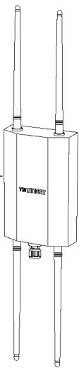
White TREAD NET device with two small ports and a black base (no visible text or symbols on body)Quick Installation Guide
TEW-941APBO (v1.xR)
1 English
- Before You Start
- Quick Reference
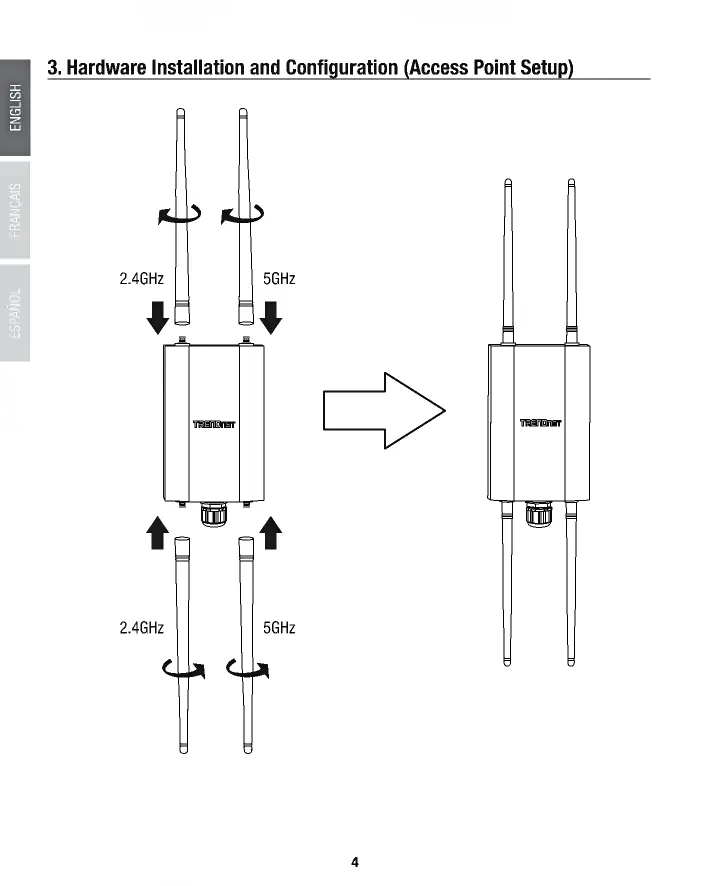
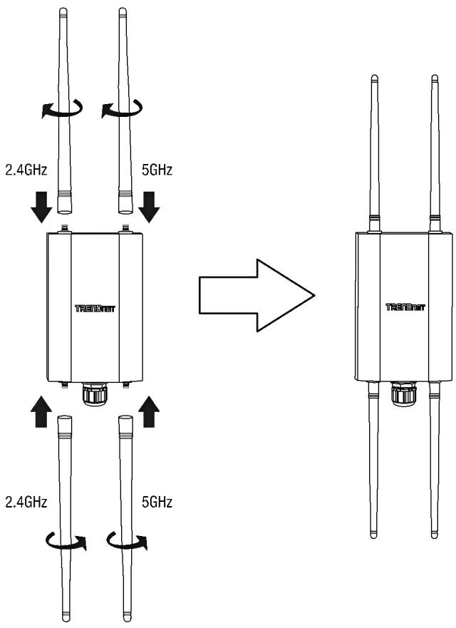
- Hardware Installation and Configuration (Access Point Setup)
- Point to Point Bridge Setup and Configuration
- Waterproof Kit Installation
- Connecting the Grounding Wire
- Mounting
https://www.trendnet.com/qig/1420

text_image
QR code image containing encoded data, no visible human-readable text30 Français
text_image
QR code image containing encoded data, no visible human-readable text59 Español
https://www.trendnet.com/qig/1430

text_image
QR code image containing encoded data, no visible human-readable textPackage Contents
- TEW-941APBO
- Quick Installation Guide
- 2 x Detachable 2.4GHz 5dBi antennas
- 2 x Detachable 5GHz 5dBi antennas
• IP67 weather rated cable gland - Mounting Hardware
Minimum Requirements
- Computer with a network port and web browser
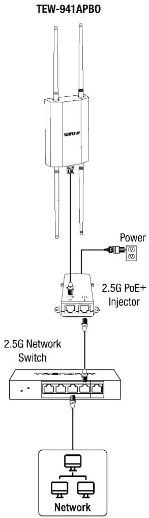
- A network switch or router with an available network 2.5G LAN PoE+ port or 2.5G PoE+ injector
- A PoE+ Network with an available LAN port connected to an existing network with Internet access and DHCP server for automatic IP addressing (required for setup with TRENDnet Hive Cloud Management only)
• RJ-45 network cables
Optional Equipment
- TRENDnet TPE-215GI (2.5G PoE+ Injector) for supplying both power and data over Ethernet to the access point if no PoE sourcing equipment is available
- Additional access point TRENDnet TEW-941APBO or TEW-940APBO (Optional for point-to-point bridging only)
- Power drill and Phillips bit or Phillips screwdriver for mounting
- Flat head bit or screwdriver for pole mounting clamp
Note: The access point complies with the IEEE 802.3at Power over Ethernet (PoE+) standard and can be used with other 802.3at PoE+ switches or PoE+ injectors to deliver both power and data to the access point through the network LAN (PoE) port.
IMPORTANT NOTE: The device does not have a hardware reset button. When changing the administrator password in the access point configuration page, please make sure to write down your new password.
2. Quick Reference
Note: By default, the wireless network name/SSID and wireless encryption settings have been pre-configured for your convenience and can be located on the included preset wireless setting sticker or on the device label located on the back of the access point. By default, the access point web management configuration page can be accessed using the URL http://tew-941apbo or using the default LAN IP address http://192.168.10.100. At default settings and initial setup, if the access point is connected to a network with a DHCP server providing IP address settings automatically, the access point will obtain IP address settings from the network DHCP server and if no DHCP server is available, the access point will use the default IP address settings 192.168.10.100 / 255.255.255.0. and you will need to manually configure your access point with the appropriate IP address and DNS server settings for Internet access. A network router is a typical DHCP server.
Preset Wireless Settings
Wi-Fi Name/SSID [AX/AC/N/A] TRENDnet941_5GHz_XXXX [AX/N/B/G] TRENDnet941_2.4GHz_XXXX
Wi-Fi Password 941XXXXXXXXX
Management Login
http://tew-941apbo username: admin password: admin
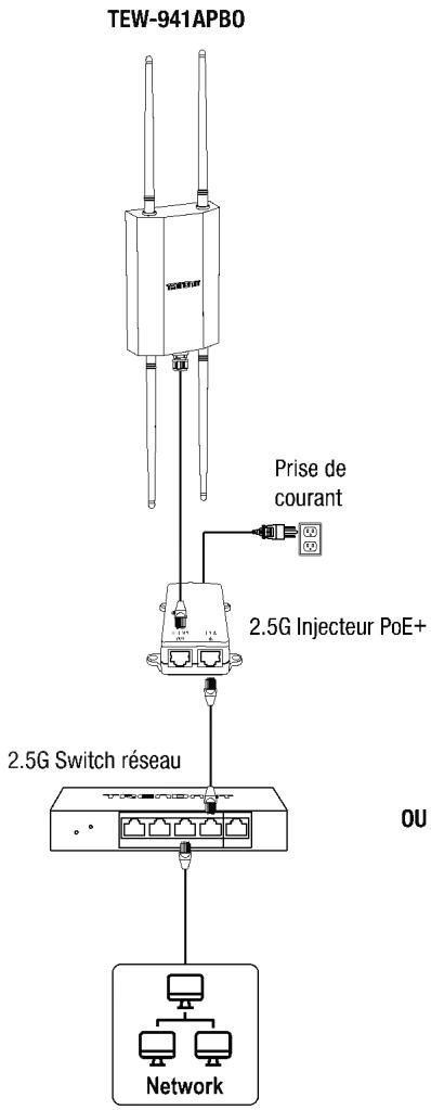
text_image
TEW-941APBO Power 2.5G PoE+ Injector 2.5G Network Switch NetworkOR
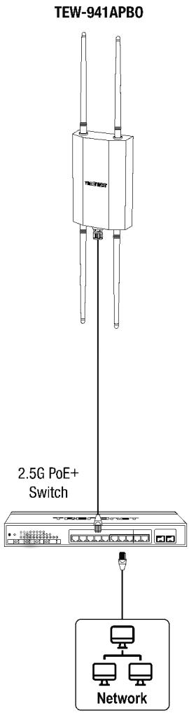
text_image
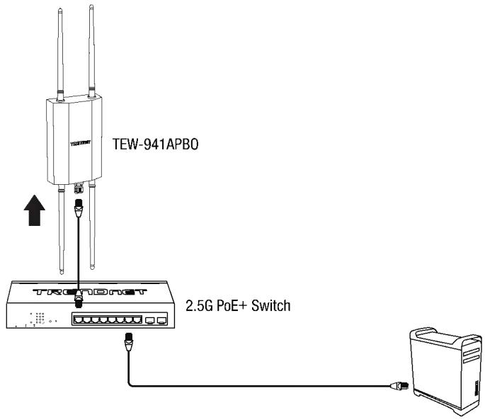
TEW-941APBO 2.5G PoE+ Switch Network3. Hardware Installation and Configuration (Access Point Setup)
If you are configuring the access point to be managed from your existing TRENDnet Hive cloud account, please follow the steps in SECTION A. If you are configuring the access point for local network management only, please follow the steps in SECTION B.
SECTION A: Configuring the access point with TRENDnet Hive Cloud Management
Configuration with TRENDnet Hive Cloud Management requires an existing network with Internet access and DHCP server for automatic IP addressing. The access point must be configured to reach the Internet in order to connect to your TRENDnet Hive Management account.
It is strongly recommended to configure the access point first before mounting.
- Connect an Ethernet/network cable to your PoE+ switch and to your access point.
- Connect an Ethernet/network cable to your computer and one of the PoE+ switch ports.
- Connect another Ethernet/network cable to one of the PoE+ switch ports and your existing network with a Internet access and DHCP server for automatic IP addressing.
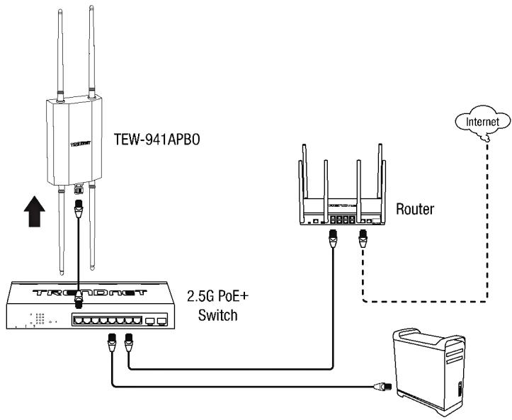
flowchart
graph TD
    A["TEW-941APBO"] -->|USB| B["2.5G PoE+ Switch"]
    B --> C["Router"]
    C --> D["Internet"]
    A -->|USB| E["2.5G PoE+ Switch"]
    E --> F["Router"]
    F --> G["Internet"]
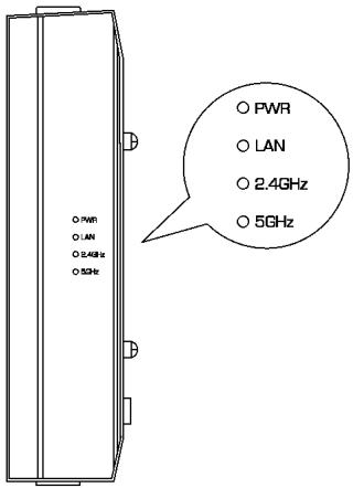
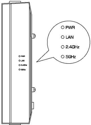
- The PWR, LAN, 2.4GHz, 5GHz LEDs will turn on to indicate that the access point is ready. Please refer to the LED definition table below.
| LED | Status | Description |
| PWR | Blinking | Device boot up |
| Solid Green | Device is operating normally | |
| LAN | Solid Green | 2.5G Data link established |
| Solid Orange | 1G Data link established | |
| Blinking | Data transmission | |
| 2.4GHz | Solid Green | 2.4GHz radio is enabled |
| Blinking | Data transmission | |
| 5GHz | Solid Green | 5GHz radio is enabled |
| Blinking | Data transmission |
-
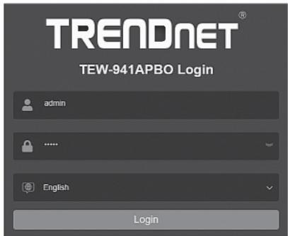
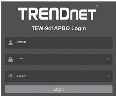
Select your language from the Language drop-down list and enter the User name and Password, and then click Login. By default:
-
User Name: admin
- Password: admin
text_image
TRENDNET® TEW-941APBO Login admin ...... English Login- Click Next on the Setup Wizard. If the setup wizard does not appear, click the setup wizard button in the top right section of the access point management page to access the setup wizard.
Setup Wizard
This wizard will guide you through a step-by-step process to configure your AP and connect to the Internet
Next
Cancel
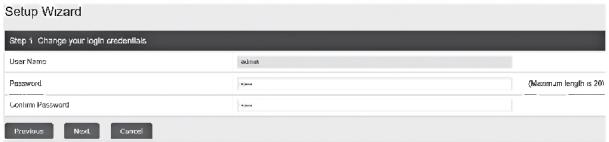
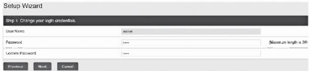
- You can change the access point administrator password by typing in the new password in the fields provided, then click Next. If entering a new password, please note that you will need to use the new password when logging into the access point management page for local access management moving forward.
IMPORTANT NOTE: The device does not have a hardware reset button. When changing the administrator password in the access point configuration page, please make sure to write down your new password.
text_image
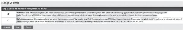
Setup Wizard Step 1 Change your login credentials User Name: Password: Confirm Password: Previous Next Cancel- For the method of management, select TRENDnet Hive. After selecting TRENDnet Hive, click Next. Configuration with TRENDnet Hive Cloud Management requires an existing network with Internet access and DHCP server for automatic IP addressing. The access point must be configured to reach the Internet in order to connect to your TRENDnet Hive Cloud Management account. If the access point is unable to obtain IP address settings and DNS from the DHCP server and unable to reach the Internet, registration of the access point to your TRENDnet Hive cloud management account will fail.
text_image
Setup Wizard Step 2: Select the method of misuseytes for this AP TRINCH/All methods. Choose this option if you would be an estimate your AP through TRINCH/All Method Development. This option will automatically apply a CMCH connection (Dynamic IP Addition) to your AP. This option will be a TRINCH/All method which will also be converted to a CMCH connection. Checking the options required, or whether it is not to be the direct non-response steps. Default management. Choose this option if you would be the estimate your AP through the local GU. You may refer to our TRINCH/All has a time point. Please write for default data APs configuration to tabacemically suitable IP all options, settings, and users. Perform needed to your relevant, if business or CMCH/All options are available, the plans are on the AP will be set up in TRINCH/All (50%): 2% (2%) Review Next Cancel- Select your Time Zone, then click Next.
text_image
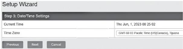
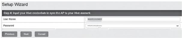
Setup Wizard Step 3: Date/Time Settings Current Time Thu Jun, 1, 2023 00 25 02 Time Zone GMT-08 00 Pacific Time (US)Canada), Tjusna Previous Next Cancel- Enter the user account credentials for your TRENDnet Hive Cloud Management account to register the access point with your account, then click Next.
text_image
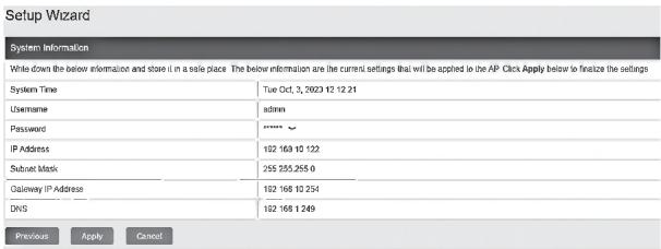
Setup Wizard Step 4: Input your Hive credentials to sync the AP to your Hive account. User Name: xxxxxxxxxxx Password: Microsoft@xxx.com Previous Next Cancel- The summary page will display all of the configuration settings that were applied through the setup wizard. Click Apply to complete the setup wizard. Please note the new password and IP settings for local access management to the access point.
text_image
Setup Wizard System Information Write down the below information and store it in a sole place. The below information are the current settings that will be applied to the AP. Click Apply below to finalize the settings System Time Tue Oct. 3, 2023 12:21 Username admin Password ****** IP Address 182 169 122 Subset mask 255 255,255 0 Gateway IP Address 182 168 1254 DNS 182 168 1249 Previous Apply Cancel- To verify the access point is now successfully registered with your TRENDnet Hive Cloud Management account, the Hive button in the top right will be green to indicate successful registration.

SECTION B: Configuring the access point for local network management
It is strongly recommended to configure the access point first before mounting.
- Connect a network cable from a PoE+ switch to your access point.
- Connect an Ethernet/network cable to your computer and one of the PoE+ switch ports.
text_image
TEW-941APBO 2.5G PoE+ Switch- The PWR, LAN, 2.4GHz, 5GHz LEDs will turn on to indicate that the access point is ready. Please refer to the LED definition table below.
| LED | Status | Description |
| PWR | Blinking | Device boot up |
| Solid Green | Device is operating normally | |
| LAN | Solid Green | 2.5G Data link established |
| Solid Orange | 1G Data link established | |
| Blinking | Data transmission | |
| 2.4GHz | Solid Green | 2.4GHz radio is enabled |
| Blinking | Data transmission | |
| 5GHz | Solid Green | 5GHz radio is enabled |
| Blinking | Data transmission |
text_image
O NVR O LAN O 5.4GHz O 5GHz ○ PWR ○ LAN ○ 2.4GHz ○ 5GHz-
Assign a static IP address to your computer's network adapter in the subnet of 192.168.10.x (e.g. 192.168.10.25) and subnet mask of 255.255.255.0. For more information on assigning a static IP address to your computer's network adapter, please refer to item Q1 in the last section of the installation guide, Installation Tips and Troubleshooting.
-
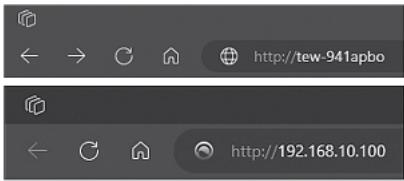
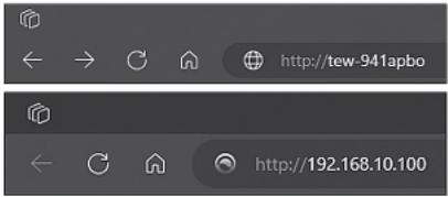
Open your web browser, type the default URL http://tew-941abpo or default IP address http://192.168.10.100 of the wireless access point in the address bar and then press Enter.
text_image
http://tew-941apbo http://192.168.10.100-
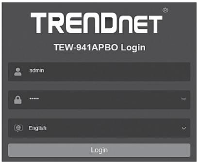
Select your language from the Language drop-down list and enter the User name and Password, and then click Login. By default:
-
User Name: admin
- Password: admin
text_image
TRENDNET® TEW-941APBO Login admin ...... English Login- Click Next on the Setup Wizard. If the setup wizard does not appear, click the setup wizard button in the top right section of the access point management page to access the setup wizard.
Setup Wizard
This wizard will guide you through a step-by-step process to configure your AP and connect to the Internet
Next
Cancel
- You can change the access point administrator password by typing in the new password in the fields provided, then click Next. If entering a new password, please note that you will need to use the new password when logging into the access point management page for local access management moving forward.
IMPORTANT NOTE: The device does not have a hardware reset button. When changing the administrator password in the access point configuration page, please make sure to write down your new password.
text_image
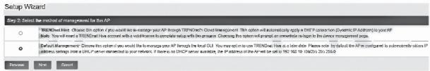
Setup Wizard Step 1 Change your login credentials. User Name: Password: Custom Password: Previous Next Cancel >>>> ... (Maximum length is 200)- For the method of management, select Default Management, click Next.
text_image
Setup Wizard Step 2: Select the method of management for the IP ○ TRNO/CH's choice. Choose this option if you will not be immediate your IP through TRNO/CH Closed Management. This option will automatically apply a DNET protection (Dynamic IP Addition) to your IP. Make the system to access the IP within which you will continue to complete its system to ensure that this option will perform on permission to help your system to manage your IP. ● Default Management. Choose this option if you will be immediate your IP through the local OUI. You may not be used in TRNO/CH (see a short time). Please note http://data.org/ATM30103/10.0001/26.2529) © TrNO/CH's choice. Use the system to access your IP within which you will not be immediate your IP.- Configure the access point date and time settings, click Next.
text_image
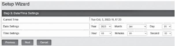
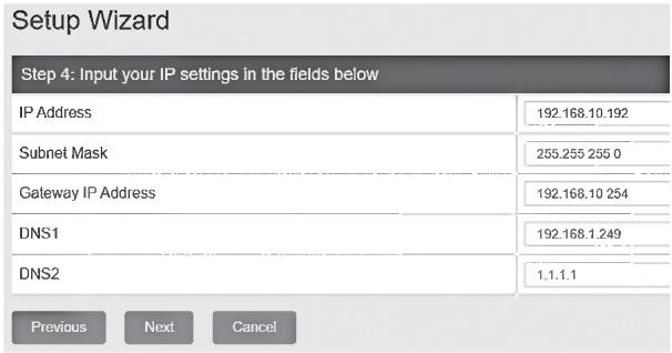
Setup Wizard Step 3: Date/Time Settings Current Time Date Settings Year 2023 Month Jun Day 01 Time Settings Hour 00 Minutes 00 Second 00 Previous Next Cancel- Configure the access point IP address, subnet mask, gateway IP address, and DNS settings to match the requirements of your existing network using the fields provided, then click Next.
Note: This step will configure static IP address settings on your access point. If the access point IP address settings are changed to a different IP network subnet such as 192.168.1.x, 192.168.2.x, etc. your computer's network adapter settings will need to be changed to match the new IP address settings configured on the access point in order to access the access point management page.
text_image
Setup Wizard Step 4: Input your IP settings in the fields below IP Address 192.168.10.192 Subnet Mask 255.255 255 0 Gateway IP Address 192.168.10 254 DNS1 192.168.1.249 DNS2 1.1.1.1 Previous Next Cancel- The summary page will display all of the configuration settings that were applied through the setup wizard. Click Apply to complete the setup wizard. Please note the new password and IP settings for local access management to the access point.
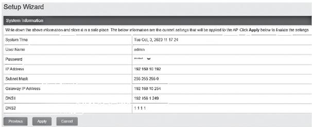
text_image
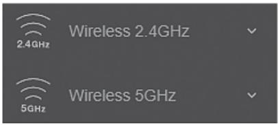
Setup Wizard System information Write down the above information and store at in a safe place. The below information are the current settings that will be applied to the AP. Click Apply below to Enalize the settings System Time Tue Oct, 3, 2023 11 17:24 User Name admin Password IP Address 192 1568 10 192 Submit Mask 255 255 255 0 Gateway IP Address 192 1568 10 254 DNS1 192 1568 1 249 DNS2 1 1 1 1 Previous Apply Cancel- To configure your wireless network name/SSID and wireless encryption settings, click the wireless band you would like to configure Wireless 2.4GHz or Wireless 5GHz and click on Wireless Network. By default, the wireless network name/SSID and wireless encryption have been pre-configured for your convenience and can be located on the included wireless settings sticker or on the device label located on the back of the access point. If you are modifying the wireless settings, you will need to connect to the access point with your WiFi client using the new settings.
text_image
2.4GHz Wireless 2.4GHz 5GHz Wireless 5GHz- In the Current Profiles, in the first entry, you can enter a new SSID, change the Security Mode and WiFi Password. Click Apply at the bottom of the page.

text_image
Current Profiles Index | Status | SMO | Security Mode | Password | Edit / Add 1 | Enrolled | TRDN23m541_2-6542_A670 | VIPA2-P3XWVPA3-SAZ Mixed/ACB | Edit- In the top right main menu, click on the Save button to commit the configuration changes.
Important Note: Configuration changes in the access point web management page are not applied until you click the Save button. This allows you to make multiple configuration changes and apply multiple changes all at the same time. Additionally, you can click the Save button on the left side to view pending unsaved configuration changes.
- After you have completed the access point configuration, reconfigure your computer's network adapter back to the original settings to obtain IP address settings automatically using DHCP, or enter the IP settings.
For more information on reconfiguring your computer's network adapter to obtain IP address settings automatically using DHCP, please refer to item Q2 in the last section of the installation guide, Installation Tips and Troubleshooting.
4. Point to Point Bridge Setup and Configuration
Note:
- The initial configuration should be completed in a testing environment with the TEW-941APBO and additional access point TEW-941APO or TEW-940APBO approximately 15ft. (5 m) apart from one another. If using the TEW-940APBO directional access point, the front panel should be directly facing the TEW-941APBO.
- It is strongly recommended to configure and connect the access points before mounting.
- In this example, we will configure the TEW-941APBO 5GHz Wireless settings and configure an additional TEW-941APBO or TEW-940APBO to create a wireless bridge to the first access point on the 5GHz Wireless band.
Phase 1: Overview
In this installation guide, we will assume the following:
Router Settings
Default Gateway IP address: 192.168.10.1
Subnet Mask: 255.255.255.0
TEW-941APB0 #1
IP Address: 192.168.10.50
Subnet Mask: 255.255.255.0
Default Gateway: 192.168.10.1
Primary DNS: 1.1.1.1
Operation Mode: Access Point
Wireless Security: WPA3-SAE AES Encryption
TEW-941APBO #2 or TEW-940APBO
IP Address: 192.168.10.51
Subnet Mask: 255.255.255.0
Default Gateway: 192.168.10.1
Primary DNS: 1.1.1.1
Operation Mode: Client Bridge
Wireless Security: WPA3-SAE AES Encryption
Phase 2: Configure the TEW-941APBO #1 Settings
Note: The predefined wireless configuration settings may be used found on the included wireless sticker, device label, or follow the configuration steps to below to manually configure a specific wireless SSID and password for the wireless bridge.
- Open your web browser, type the default URL http://tew-941abpo or default IP address http://192.168.10.100 of the wireless access point in the address bar and then press Enter.
text_image
http://tew-941apbo http://192.168.10.100-
Select your language from the Language drop-down list and enter the User name and Password, and then click Login. By default:
-
User Name: admin
- Password: admin
text_image
TRENDNET® TEW-941APBO Login admin **** English Login- In the left navigation menu, click System and IP Settings.
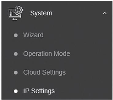
text_image
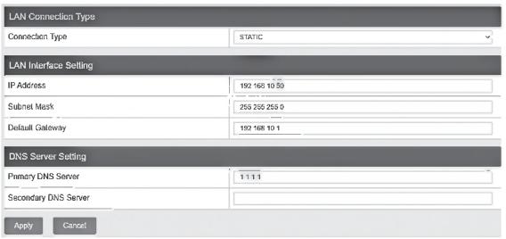
System • Wizard • Operation Mode • Cloud Settings • IP Settings- Click the Connection Type drop-down list and select STATIC, and enter the IP Address 192.168.10.50, Subnet Mask 255.255.255.0, Default Gateway 192.168.10.1, and Primary DNS Server 1.1.1.1, then click Apply.
Note: You will need to log back into the access point management page using the new IP address settings.
text_image
LAN Connection Type Connection Type STATIC LAN Interface Setting IP Address 192 168 10 50 Subnet Mask 255 255 255 0 Default Gateway 192 168 10 1 DNS Server Setting Primary DNS Server 1 1 1 1 Secondary DNS Server Apply Cancel- In the left navigation menu, click Wireless 5GHz and Wireless Network.
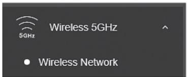
text_image
Wireless 5GHz 5GHz • Wireless Network- For the first entry that pre-configured, click Edit in the right column.
| Current Profiles | |||||
| Index | Scotus | SSID | Security Mode | Password | Edit / Add |
| 1 | Enabled | TRENDex3LX_MSH_ASP4 | WPA2:PS4WVPA3:GAE Nasi AES | Edit | |
- At the top under Wireless Settings, you can change the default SSID in the SSID field.
Note: Please note the SSID as it will be needed to connect the second access point to create the wireless bridge.

text_image
Wireless Settings SSID TRENDm0941_5GHz_A670- Under the Wireless Security section, click the drop-down to select the wireless security mode to use.
Note: For general wireless client device compatibility, it is recommended to use WPA3-Personal Mixed AES. For wireless bridging with an additional TEW-941APBO or TEW-940APBO, it is recommended to use the highest supported WPA3-Personal AES.
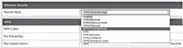
text_image
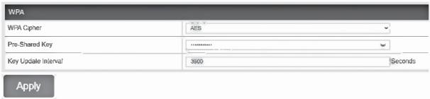
Wireless Security Security Mode WPA3-Personal Mixed Disabled WPA2-Personal WPA2-Personal Mixed WPA3-Personal Mixed WPA3-Personal Mixed GWE Pre-Shared Key WPA-Enterprise WPA2-Enterprise WPA2-Enterprise Mixed Key Update Interval 6009 Seconds- Enter the WiFi Password or Pre-Shared Key in the Pre-Shared Key field and click Apply at the bottom of the page. (8-63 alphanumeric characters)
Note: Please make note of the WiFi password or pre-shared key assigned as it will be used for the configuration of the second access point to make the wireless bridge.
text_image
WPA WPA Cipher AES Pre-Shared Key ****** Key Update Interval 3900 Seconds Apply- In the top right main menu, click on the Save button to commit the configuration changes.
Phase 3: Configure the TEW-941APBO #2 or TEW-940APBO Settings
When configuring the second TEW-941APBO access point or TEW-940APBO, repeat 1-3 of the steps in Phase 2: Configure the TEW-941APBO #1 Settings.
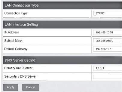
- In Step 4, click the Connection Type drop-down list and select STATIC, and enter the IP Address 192.168.10.51, Subnet Mask 255.255.255.0, Default Gateway 192.168.10.1, and Primary DNS Server 1.1.1.1, then click Apply.
Note: You will need to log back into the access point management page using the new IP address settings.
text_image
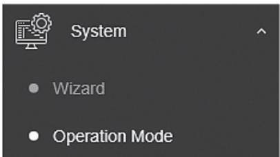
LAN Connection Type Connection Type STATIC LAN Interface Setting IP Address 192 168 10 51 Subnet Mask 255 255 255.0 Default Gateway 192 168 10 1 DNS Server Setting Primary DNS Server 1.1.1.1 Secondary DNS Server Apply Cancel- In the left navigation menu, click System and Operation Mode.
text_image
System • Wizard • Operation Mode- Click Operation Mode drop-down list and select Client Bridge, then click Apply.
Note: If using the TEW-940APBO, the field will be named 5GHz Operation Mode.

text_image
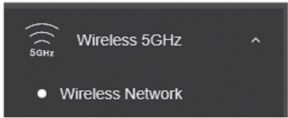
Device Name : TEW-940APBO 5GHz Operation Mode Client Bridge Apply Cancel- In the left navigation menu, click Wireless 5GHz and Wireless Network.
text_image
5GHz Wireless 5GHz • Wireless Network- In the Wireless Network section, click on Site Survey.
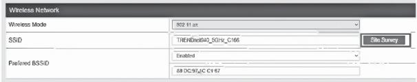
text_image
Wireless Network Wireless Mode 802.11 at SSD TRENDex940_5GHz_C166 Preferred BSSD Enabled 68 DC 97/2C C1 57 File Survey- In the Site Survey list, find the SSID configured on the first access point TEW-941APBO and select it by clicking on the entry.
| S50 | S550 | Channel | Signal Level | Type | Security | Notes |
| TRENDexHL_90HJ_A2F6 | DC 12:55-A2F62 | 48 | -25 dBm | RASAHESE | WHA-SDF mixed | HP |
| TRENDexHL_92HJ_90HJ | DB 8:57 DC 9B 52 | 141 | -25 dBm | MAC VERTO | WENA-FIX4 | HP |
| TRENDexHL_92HJ_90HJ | DB 8:57 23-04-03 | 157 | -25 dBm | MAC VERTO | WENA-FIX4 | HP |
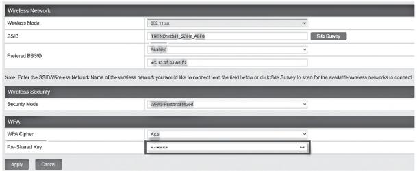
- The details of the selected SSID will be entered in to the wireless section automatically. Under the Wireless Security section under WPA, enter the Pre-Shared Key configured on the first access point and click Apply.
text_image
Wireless Network Wireless Mode 502.13 as SS/D TRENDv681_90HL_ASP9 Site Survey Preferred BSID Busted 45 to 65 or 85 AFS Note: Enter the SSD/Wireless Network Name of the wireless network you would like to connect to in the field below or click file Survey to scan for the available wireless networks to connect. Wireless Security Security Mode: WPS-Formal Model WPA WPA Cipher ACS Pre-Sistered Key Apply Cancel- In the top right main menu, click on the Save button to commit the configuration changes.
Phase 4: Confirm Connectivity
- Leave your computer connected to TEW-941APBO #2 or TEW-940APBO and keep the access point configuration page open.
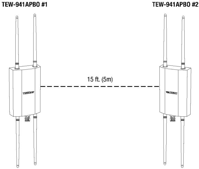
- Make sure both TEW-941APBO #1 and TEW-941APBO #2 access points are powered on approximately 15 ft. (5 m) apart from one another.
text_image
TEW-941APBO #1 15 ft. (5m) TEW-941APBO #2- To verify connectivity, in the TEW-941APBO #2 or TEW-940APBO access point configuration page, click Management and click Diagnostics. Under the Ping Test Parameter section, enter the IP Address of the TEW-941APBO #1, 192.168.10.50, then click Ping.
| Ping Test Parameter | |
| IP Address | 192.168.10.50 |
| Packet Length | 64 |
| Number of Pings | 4 |
- Ping replies and 0% packet loss will indicate a successful point to point bridge connection between the TEW-941APBO #1 and TEW-941APBO #2 or TEW-940APBO access points.
Note: If the connectivity test fails, wait for about 1 minute and try again. Make sure there are no obstacles between the two access points when running the connectivity test and make sure the access points are not too close together.
Diagnostics Result
PING 192.168.10.50 (192.168.10.50): 64 data bytes
72 bytes from 192.168.10.50: seq=0 ttl=64 time=4.873 ms
72 bytes from 192.168.10.50: seq=1 ttl=64 time=4.072 ms
72 bytes from 192.168.10.50: seq=2 ttl=64 time=4.104 ms
72 bytes from 192.168.10.50: seq=3 ttl=64 time=4.136 ms -- 192.168.10.50 ping statistics --
4 packets transmitted, 4 packets received, 0% packet loss round-trip min/avg/max = 4.072/4.296/4.873 ms
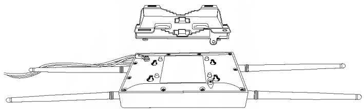
5. Waterproof Kit Installation
Note: The waterproof kit can only be installed with non-terminated Ethernet cabling. The Ethernet cable can be properly terminated after installing the waterproof kit.
- Unscrew the sealing nut from the main body of the access point.
- Separate the rubber seal from the claw.
- Verify that you have the following parts:

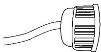
- Insert one end of an Ethernet cable into the sealing nut.
natural_image
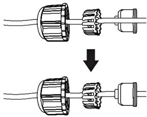
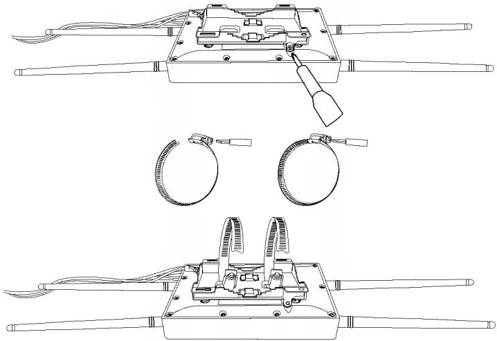
Simple line drawing of a cylindrical object with internal grooves (no text or symbols)- Insert the Ethernet cable into the seal.
Note: After the non-terminated Ethernet cable is installed through the sealing nut, claw and seal, the cable may be properly terminated.
natural_image
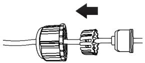
Diagram showing two stages of a plug or socket assembly, with no text or symbols present.- Insert the seal into the claw.
natural_image
Mechanical assembly diagram showing gear and shaft components with an arrow indicating direction (no text or labels)- Insert the seal/rubber claw into the Cable Gland.

natural_image
Three technical line drawings of a mechanical connector assembly (no text or symbols)- Connect the Ethernet cable to the 2.5G LAN PoE+ port on the bottom of the access point.
- By hand, screw the main body counter clockwise to secure it to the access point.
- By hand, screw the seal nut clockwise to secure it to the main body.
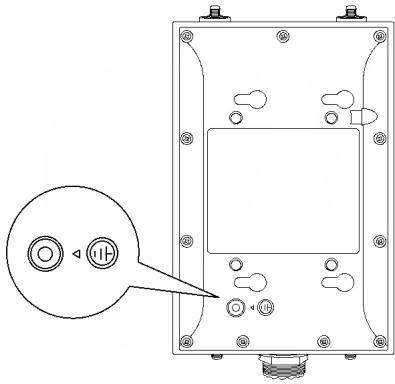
6. Connecting the Grounding Wire
- Identify the grounding point on the back of the access point.
natural_image
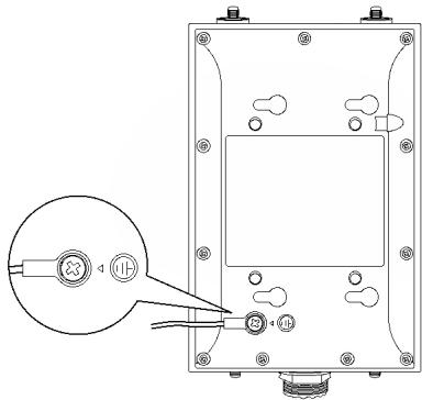
Technical line drawing of a mechanical or electronic component with mounting holes and a circular button labeled 'HP' (no text or symbols beyond basic diagram)- Align one end of the grounding wire over the grounding point and secure the grounding wire with the provided screw and washers turning clockwise
natural_image
Technical line drawing of a mechanical or electrical component with mounting holes and a magnified inset showing a circular feature (no text or symbols)- Connect the other end of the grounding wire to a grounded object. (e.g. earth driven rod, grounding electrical system)
7. Mounting
- Install the metal mounting bracket by aligning the four bracket points to the four mounting holes on the back of the access point. The hole for the mount bracket locking screw should be located at the top right when installing the mounting bracket to the access point.
natural_image
Technical line drawing of an electronic device with exposed components and wiring (no text or symbols)- After installing the mounting bracket to the back of the access point, slide the mounting bracket left and install the locking screw by turning clockwise.
natural_image
Technical line drawings of a mechanical device with three views: top, side, and bottom (no text or symbols)Note: If mounting the TEW-940APBO with directional antenna, please make sure that the access point is mounted with the same vertical height, within line of sight, and facing the direction of the TEW-941APBO to allow for the optimal connectivity.
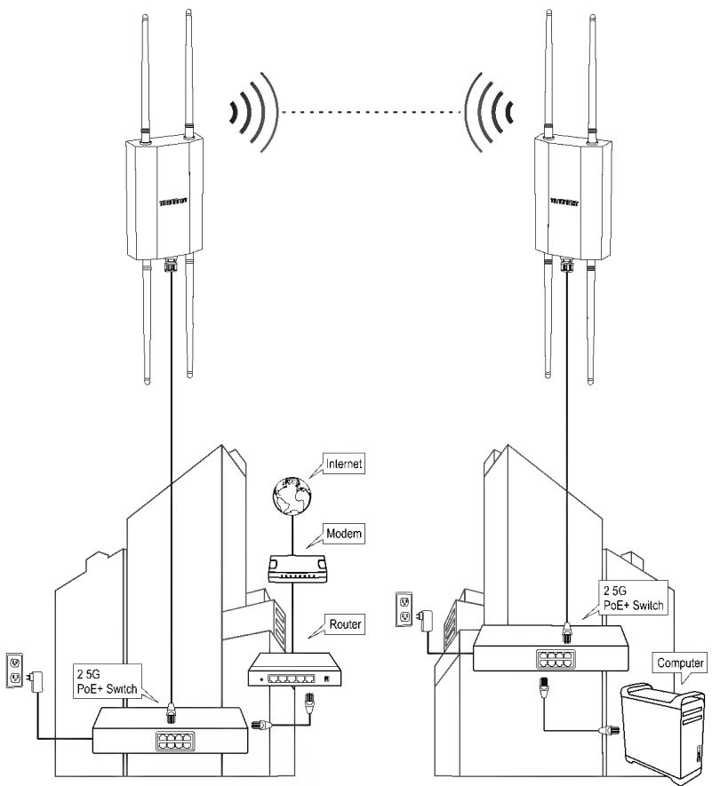
Completed Installation Reference
text_image
25G PoE+ Switch Internet Modem Router 2 5G PoE+ Switch 2 5G PoE+ Switch ComputerBuilding 1
Building 2
http://tew-941apbo username: admin password: admin
This wizard will guide you through a step-by-step process to configure your AP and connect to the Internet.
Next
Cancel
text_image
Setup Wizard Step 1 Change your login credentials User Name: Password: Confirm Password: Previous Next Cancel akaiya *** *** *** Maximum length is 200text_image
Setup Wizard Step 2: Select the method of businesses for this IP TRENCHO's client. Choose this option if you will also be an expensive your IP through TRENCHO's Client Management. This option will automatically apply a TRENCHO's client (DynamicIP Addition) to your IP. Default Management. Choose this option if you will be an expensive your IP. For this local OSI. You may not use a TRENCHO's client in order. Please note that additional the IP component can be installed to your IP. All other settings include this option. If you are connected to your clients, it means to a TRENCHO user with the IP address on the Web site and is 100, 500, 100, 200, 250 or 300.text_image
Setup Wizard Step 3: Date/Time Settings Current Time Thu Jun, 1, 2023 00 25 02 Time Zone GMT-08 00 Pacific Time (US)Canada), Tjusna Previous Next Canceltext_image
Setup Wizard Step 4: Input your Hive credentials to sync the AP to your Hive account. User Name: xxxxxxxxxxxx Password: Preval Next Canceltext_image
Setup Wizard System Information Write down the below information and store it in a site place. The below information are the current settings that will be applied to the AP. Click Apply below to finalize the settings System Time Tue Oct 3, 2023 12:12:21 Username admin Password IP Address 102 169 10 122 Subset mask 255 255,255 0 Gateway IP Address 102 168 10 254 DNS 102 166 1 249 Previous Apply CancelThis wizard will guide you through a step-by-step process to configure your AP and connect to the Internet.
Next
Cancel
text_image
Setup Wizard Step 1. Change your login credentials User Name Password Confirm Password Previous Next Cancel admin (Neasurement length is 200)text_image
Setup Wizard Step 2: Setup the method of management for this AP ○ TRINERDirect Flow. Contains this option if you would be to remote your AP through TRINERDirect Cloud Management. This option can automatically apply a TCP connection (Windows, IP Address) to your AP. Note: The will cover a TRINERDirect flow account with the following functions: Windows is not available to the TCP connection via the TCP connection map. ● Default Management. Check this option's key view(s) to the remote your AP through the local GIS. The map may be used to monitor TRINERDirect. Use a link to a network device. Please note, by default, the AP is configured to automatically adjust IP address settings from an TCP access controller to your network. If there is no TCP access controller, the IP address is on the AP site set at 202.198.15.160025.205.205.0 Previous Next Canceltext_image
Setup Wizard Step 3: Date/Time Settings Current Time Date Settings Year 2023 Month Jan Day 01 Time Settings Hour 00 Minutes 00 Second 00 Previous Next Canceltext_image
Setup Wizard Step 4: Input your IP settings in the fields below IP Address 192.168.10.192 Subnet Mask 255.255 255 0 Gateway IP Address 192.168.10 254 DNS1 192.168.1.249 DNS2 1.1.1.1 Previous Next Canceltext_image
Setup Wizard System Information Write down the above information and store it in a safe place. The below information are the current settings that will be applied to the AP. Click Apply below to finalize the settings System Time User Name Password IP Address Submit Mask Gateway IP Address DNS1 DNS2 Tue Oct, 3, 2023 11 17:24 address user 192 168 10 192 255 255 255 0 192 168 10 254 192 168 1 249 1 1 1 1 Previous Apply Canceltext_image
2.4GHz Wireless 2.4GHz 5GHz Wireless 5GHztext_image
Wireless 5GHz 5GHz • Wireless Networktext_image
Wireless Security Security Mode WPA2-Personal Mixed Disabled WPA2-Personal WPA2-Personal Mixed WPA2-Cipher WPA2-Enterprise Mixed CWE WPA-Enterprise WPA2-Enterprise WPA2-Enterprise Mixed Key Update Interval 5000 Secondstext_image
WPA WPA Cipher AES Pre-Shared Key Key Update Interval 3600 Seconds Applytext_image
Device Name : TEW-940APBO 5GHz Operation Mode Client Bridge Apply Canceltext_image
5GHz Wireless 5GHz • Wireless Networktext_image
Wireless Network Wireless Mode 502.13.x SS/D TRENDWRST_SKPL_AEP Site Survey Preferred BSS/D Busted 45 to 65/81 AEPs Note: Enter the SSD/Wireless Network Name of the wireless network you would like to connect to in the field below or click Site Survey to scan for the available wireless networks to connect. Wireless Security Security Mode: WPS-Formal Mask WPA WPA Cipher ACS Pre-Served Key Apply Cancel72 bytes from 192.168.10.50: seq=0 ttl=64 time=4.873 ms
72 bytes from 192.168.10.50: seq=1 ttl=64 time=4.072 ms
72 bytes from 192.168.10.50: seq=2 ttl=64 time=4.104 ms
72 bytes from 192.168.10.50: seq=3 ttl=64 time=4.136 ms
-- 192.168.10.50 ping statistics --
4 packets transmitted, 4 packets received, 0% packet loss
round-trip min/avg/max = 4.072/4.296/4.873 ms
natural_image
Simple line drawing of a cylindrical object with internal grooves (no text or symbols)natural_image
Diagram showing two stages of a plug or socket assembly, with no text or symbols present.natural_image
Diagram of a mechanical assembly showing a shaft and housing with an arrow indicating direction (no text or symbols)natural_image
Three schematic diagrams of electrical connectors with internal components, no text or symbols presentnatural_image
Technical line drawing of a mechanical component with mounting holes and a circular button labeled 'I' (no text or symbols beyond basic diagram)natural_image
Technical line drawing of a mechanical device with mounting holes and a close-up inset showing a circular component (no text or symbols)natural_image
Technical line drawing of an electronic device housing with internal components and wiring (no text or symbols)natural_image
Technical line drawings of a mechanical device with three views: top, front, and side (no text or symbols)This wizard will guide you through a step-by-step process to configure your AP and connect to the Internet
Next
Cancel
text_image
Setup Wizard Step 1 Change your login credentials User Name: Password: Confirm Password: Previous Next Canceltext_image
Setup Wizard Step 2: Select the method of misuseytes for this AP TRENCHO lists. Choose this option if you would be installed on your AP through TRENCHO Closed Development. This option will automatically apply a CMCH connection (Dynamic IP Addition) to your AP. This option will be created in the context of the application to create a CMCH connection. Checking the option's forward response in your IP to ensure the system's improvement needs. Default management. Choose this option if you would be installed on your AP through the local GU. You may not be used in TRENCHO have a little bit. Please write for default mode APs configuration to automatically install IP options, settings, and users. Further removed your features, if business is CMCH based on the PAGAPs on the IP will not be at 100.768.79 (50/21):21.cmd Review Next Canceltext_image
Setup Wizard Step 3: Date/Time Settings Current Time Thu Jun, 1, 2023 00 25 02 Time Zone GMT-08 00 Pacific Time (US/Canada), Tjusna Previous Next Canceltext_image
Setup Wizard Step 4: Input your Hive credentials to sync the AP to your Hive account. User Name: xxxxxxxxxxxx Password: Preval Next Canceltext_image
Setup Wizard System Information Write downs the below information and store it in a sole place. The below information are the current settings that will be applied to the AP. Click Apply below to finalize the settings System Time Username admin Password IP Address 102 169 10 122 Subset mask 255 255,255 0 Gateway IP Address 102 168 10 254 DNS 102 166 1 249 Previous Apply Canceltext_image
Setup Wizard This wizard will guide you through a step-by-step process to configure your AP and connect to the Internet Next Canceltext_image
Setup Wizard Step 1 Change your login credentials User Name: Password: Confirm Password: Previous Next Canceltext_image
Setup Wizard Step 2: Select the method of management for the IP ○ TRINCHNE will change this option if you should be executed on your AP from TRINCHNE. This option is automatically applied by a CHF Foundation (DversicIP) Application to your AP. Only one's TRINCHNE has been used to define the internal permission with the license. Consider the internal permission as an alternative in the business environment. ○ Default Management. Choose this option if we should be executed on your AP through the local GUI. You must not be required to run TRINCHNE. It is a key data point. Please note that default the AP configuration is automatically using IP all information from the API. Please recommend to your relevant. If features to DHCP service available, the API contains the network to be sent to 190,762,109 (0/035, 25/25/24) Review Next Canceltext_image
Setup Wizard Step 3. Date/Time Settings Current Time Tue Oct 3, 2023 11.17 23 Date Settings Year 2023 Month Jun Day 01 Time Settings Hour 00 Minutes 00 Second 00 Previous Next Canceltext_image
Setup Wizard Step 4: Input your IP settings in the fields below IP Address 192.168.10.192 Subnet Mask 255.255 255 0 Gateway IP Address 192.168.10 254 DNS1 192.168.1.249 DNS2 1.1.1.1 Previous Next Canceltext_image
Setup Wizard System Information Write down the above information and store it in a safe place. The below information are the current settings that will be applied to the AP. Click Apply below to finalize the settings System Time Tue Oct, 3, 2023 11 17:24 User Name admin Password IP Address 192 168 10 192 Submit Mask 255 255 255 0 Gateway IP Address 192 168 10 254 DNS1 192 168 1 249 DNS2 1 1 1 1 Previous Apply Canceltext_image
2.4GHz Wireless 2.4GHz 5GHz Wireless 5GHztext_image
Current Profiles Index States ISO Security Mode Password Edit / Add I Enabled TRIID#M#S#1_2-0Hz_A#F0 VIP#2-P3XW#FA3-SAC Mixed AC#5 EditTEW-941APBO #2 o TEW-940APBO
text_image
Wireless 5GHz 5GHz • Wireless Networktext_image
Wireless Security Security Mode WPA3-Personal Mixed Disabled WPA2-Personal WPA2-Personal Mixed WPA3-Personal WPA3-Personal Mixed VWE WPA-Enterprise WPA2-Enterprise WPA2-Enterprise Mixed Pre-Shared Key Key Update Interval 3600 Secondstext_image
WPA WPA Cipher AES Pre-Shared Key ****** Key Update Interval 3600 Seconds Applytext_image
Device Name : TEW-940APBO 5GHz Operation Mode Client Bridge Apply Canceltext_image
Wireless 5GHz 5GHz • Wireless Networktext_image
Wireless Network Wireless Mode 502.13.x SS/D TRENDWRST_A690_A690 Site Survey Preferred BSSD 8x80 45-10/05/01 A6 F2 Note: Enter the SSD/Wireless Network Name of the wireless network you would like to connect to in the field below or click file Survey to scan for the available wireless networks to connect. Wireless Security Security Mode: WPS-Formal Mask WPA WPA Cipher ACS Pre-Sistered Key Apply Cancelnatural_image
Pure technical line drawing of a rectangular component with three vertical rods and a central base (no text or symbols)TEW-941APBO #2
15 ft. (5m)
natural_image
Pure technical line drawing of a mechanical component with three vertical rods and a central base (no text or symbols)72 bytes from 192.168.10.50: seq=0 ttl=64 time=4.873 ms
72 bytes from 192.168.10.50: seq=1 ttl=64 time=4.072 ms
72 bytes from 192.168.10.50: seq=2 ttl=64 time=4.104 ms
72 bytes from 192.168.10.50: seq=3 ttl=64 time=4.136 ms
-- 192.168.10.50 ping statistics --
4 packets transmitted, 4 packets received, 0% packet loss
round-trip min/avg/max = 4.072/4.296/4.873 ms
natural_image
Simple line drawing of a cylindrical object with internal grooves (no text or symbols)natural_image
Diagram showing two stages of a plug or socket assembly, with no text or symbols present.natural_image
Diagram of a mechanical assembly showing a shaft, housing, and motor (no text or labels)natural_image
Three technical line drawings of a mechanical connector assembly (no text or symbols)natural_image
Technical line drawing of a mechanical component with mounting holes and a circular button labeled 'i' (no text or symbols beyond basic diagram)natural_image
Technical line drawing of a mechanical device with mounting holes and a close-up inset showing a circular component (no text or symbols)natural_image
Technical line drawing of an electronic device housing with internal components and wiring (no text or symbols)natural_image
Technical line drawings of mechanical components with no visible text or symbolsQ1: How do I configure my computer's network adapter with a static IP address?
Note: Please note that although the following procedures are provided to follow for your operating system network adapter settings to be used as general guidelines, however, it is strongly recommended that you consult your computer or operating system manufacturer directly for assistance on the proper procedure for configuring network settings. If you are experiencing difficulties, please contact your computer or operating system manufacturer for assistance.
Windows 2000/XP/Vista/7/8/8.1/10/11
- On your keyboard, press Windows Logo + R keys simultaneously to bring up the Run dialog box.
- In the dialog box, type ncpa.cpl to bring up the Network Connections window.
- Right-click the Local Area Connection or Ethernet icon, click Properties, and double-click Internet Protocol Version 4 (TCP/IPv4).
- Then click Use the following IP address and assign your network adapter a static IP address. See example static IP address settings below.
• IP address: 192.168.10.25 -
Subnet mask: 255.255.255.0
-
Click OK on both TCP/IPv4 Properties and Local Area Connection Properties windows.
MAC OS X
- From the Apple drop-down list, select System Preferences.
- Click the Network icon.
- From the Location drop-down list, select Automatic.
-
Select and view your Ethernet connection.
-
For MAC OS 10.4, from the Show drop-down list, select Built-in Ethernet and select the TCP/IP tab.
-
For MAC OS 10.5 and above, in the left column, select Ethernet.
-
Configure TCP/IP to use a static IP.
- From the Configure IPv4 or Configure drop-down list, select Manually and assign your network adapter a static IP address. Then click the Apply or Apply Now button. See example static IP address settings below.
• IP address: 192.168.10.25
- Subnet mask: 255.255.255.0
- You may be prompted to restart your computer to apply the new IP address settings.
Q2: I configured my computer's network adapter with a static IP address, how do I reconfigure my computer's network adapter to default settings and obtain an IP address automatically using DHCP?
Note: Please note that although the following procedures are provided to follow for your operating system network adapter settings to be used as general guidelines, however, it is strongly recommended that you consult your computer or operating system manufacturer directly for assistance on the proper procedure for configuring network settings. If you are experiencing difficulties, please contact your computer or operating system manufacturer for assistance.
Windows 2000/XP/Vista/7/8/8.1/10/11
- On your keyboard, press Windows Logo + R keys simultaneously to bring up the Run dialog box.
- In the dialog box, type ncpa.cpl to bring up the Network Connections window.
- Right-click the Local Area Connection or Ethernet icon, click Properties, and double-click Internet Protocol Version 4 (TCP/IPv4).
- Then click Obtain an IP address automatically and Obtain DNS server address automatically.
- Click OK on both TCP/IPv4 Properties and Local Area Connection Properties windows.
MAC OS X
- From the Apple drop-down list, select System Preferences.
- Click the Network icon.
- From the Location drop-down list, select Automatic.
-
Select and view your Ethernet connection.
-
In MAC OS 10.4, from the Show drop-down list, select Built-in Ethernet and select the TCP/IP tab.
• In MAC OS 10.5 and above, in the left column, select Ethernet. -
Configure TCP/IP to use a static IP.
- From the Configure IPv4 or Configure drop-down list, select Using DHCP and click the Apply or Apply Now button.
- You may be prompted to restart your computer to apply the new IP address settings.
Q3: I typed http://192.168.10.100 in my Internet Browser Address Bar, but an error message says "The page cannot be displayed." How can I access the wireless access point management page?
- Double check all physical cable and port connections.
- Make sure the PWR/LAN/2.4GHz/5GHz LEDs on the wireless access point front panel are on.
- Make sure your computer's network adapter is configured with a static IP address. (Refer to Q1 for instructions on assigning a static IP address).
- Make sure your computer is connected to the access point network LAN port and LAN LED is on.
- Since the access point default IP address is 192.168.10.100, make sure there are no other network devices assigned an IP address of 192.168.10.100
Note: After checking all of the recommended items above, please attempt to access the wireless access point management page again.
Q4: How do I find the current IP address of my computer's network adapter?
Note: Please note that although the following procedures are provided to follow for your operating system network adapter settings to be used as general guidelines, however, it is strongly recommended that you consult your computer or operating system manufacturer directly for assistance on the proper procedure for configuring network settings. If you are experiencing difficulties, please contact your computer or operating system manufacturer for assistance.
Command Prompt Method
Windows 2000/XP/Vista/7/8/8.1/10/11
- On your keyboard, press Windows Logo + R keys simultaneously to bring up the Run dialog box.
- In the dialog box, type cmd to bring up the command prompt.
- In the command prompt, type ipconfig /all to display your IP address settings.
MAC OS X
- Navigate to your Applications folder and open Utilities.
- Double-click on Terminal to launch the command prompt.
- In the command prompt, type ipconfig getifaddr
to display the wired or wireless IP address settings.
Note: en0 is typically the wired Ethernet and en1 is typically the wireless Airport interface.
Graphical Method
Windows XP/Vista/7/8/8.1/10/11
- On your keyboard, press Windows Logo + R keys simultaneously to bring up the Run dialog box.
- In the dialog box, type ncpa.cpl to bring up the Network Connections window.
- Double-click the Local Area Connection icon and click the Details button to view the current IP address settings.
Note: The computer's network adapter must be enabled and connected to view the current IP address settings.
MAC OS X
- From the Apple menu, select System Preferences.
- In System Preferences, from the View menu, select Network.
- In the Network preference window, click a network port (e.g., Ethernet, AirPort, modem). If you are connected, you'll see your IP address settings under "Status:"
This device complies with Part 15 of the FCC Rules. Operation is subject to the following two conditions: (1) This device may not cause harmful interference, and (2) this device must accept any interference received, including interference that may cause undesired operation.
This equipment has been tested and found to comply with the limits for a Class B digital device, pursuant to Part 15 of the FCC Rules. These limits are designed to provide reasonable protection against harmful interference in a residential installation. This equipment generates, uses and can radiate radio frequency energy and, if not installed and used in accordance with the instructions, may cause harmful interference to radio communications. However, there is no guarantee that interference will not occur in a particular installation. If this equipment does cause harmful interference to radio or television reception, which can be determined by turning the equipment off and on, the user is encouraged to try to correct the interference by one of the following measures:
- Reorient or relocate the receiving antenna.
- Increase the separation between the equipment and receiver.
- Connect the equipment into an outlet on a circuit different from that to which the receiver is connected.
- Consult the dealer or an experienced radio/TV technician for help.
FCC Caution: Any changes or modifications not expressly approved by the party responsible for compliance could void the user's authority to operate this equipment.
This transmitter must not be co-located or operating in conjunction with any other antenna or transmitter.
IMPORTANT NOTE:
Radiation Exposure Statement:
This equipment complies with FCC radiation exposure limits set forth for an uncontrolled environment. This equipment should be installed and operated with minimum distance 20cm between the radiator & your body.
This radio transmitter FCC ID: XU8TEW941APBO has been approved by FCC to operate with antenna types listed below with the maximum permissible gain and required antenna impedance for each antenna type indicated. Antenna types not included in this list, having a gain greater than the maximum gain indicated for that type, are strictly prohibited for use with this device.
Antenna list
| No. | Manufacturer | Part No. | Antenna Type | Peak Gain |
| 1 | Master Wave | 98143MRSX000 | Dipole | 5.17dBi |
| 2 | Master Wave | 98143URSX000 | Dipole | 5.17dBi |
Certifications
This device complies with Part 15 of the FCC Rules.
Operation is subject to the following two conditions:
(1) This device may not cause harmful interference.
(2) This device must accept any interference received. Including interference that may cause undesired operation.


Waste electrical an electronic products must not be disposed of with household waste. Please recycle where facilities exist. Check with your Local Authority or Retailer for recycling advice.
Applies to PoE Products Only: This product is to be connected only to PoE networks without routing to the outside plant
Note
The Manufacturer is not responsible for any radio or TV interference caused by unauthorized modifications to this equipment. Such modifications could void the user's authority to operate the equipment
Advertencia
If you have any questions regarding the product installation, please contact our Technical Support.
Toll free US/Canada: 1-855-373-4741
Regional phone numbers available
at www.trendnet.com/support
TRENDnet
20675 Manhattan Place
Torrance, CA 90501
USA
Product Warranty Registration
Please take a moment to register your product online. Go to TRENDnet's website at:
www.trendnet.com/register