TEW-941APBO (v1.xR) - Access Point TRENDNET - Free user manual and instructions
Find the device manual for free TEW-941APBO (v1.xR) TRENDNET in PDF.



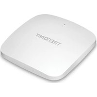
| Product Type | Outdoor access point with point-to-point wireless bridge |
| Dimensions | Approximately 200 x 200 x 50 mm (estimated) |
| Weight | Approximately 1 kg (estimated) |
| Power Supply | PoE+ IEEE 802.3at, 2.5G PoE+ port |
| Interfaces | 1 x 2.5G PoE+ Ethernet port (RJ45) |
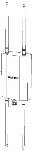
| Antennas | 2 detachable 2.4 GHz 5 dBi antennas, 2 detachable 5 GHz 5 dBi antennas |
| Wireless Standards | Wi-Fi 6 (802.11ax) dual-band simultaneous 2.4 and 5 GHz, backward compatible 802.11ac/n/a/g/b |
| Max Data Rates | Up to 2.4 Gbps (theoretical) |
| Wireless Security | WPA3-SAE AES, WPA2-PSK AES, WPA3-Personal Mixed, MAC filtering, WPS |
| Management | Web interface (HTTP/HTTPS), TRENDnet Hive cloud application, setup wizard |
| Operating Modes | Access point, Client bridge |
| Environmental Protection | IP67 waterproof kit for Ethernet cable, weatherproof housing |
| Operating Temperature | -30°C to 60°C (estimated) |
| Mounting | Metal bracket for pole or wall (included), mounting clamp |
| Grounding | Ground point on rear, ground cable provided |
| Initial Configuration | Via browser at http://tew-941apbo or 192.168.10.100, credentials admin/admin |
| Reset | No reset button; note admin password imperative |
| Package Contents | Access point, 2 x 2.4 GHz antennas, 2 x 5 GHz antennas, quick guide, waterproof kit, mounting hardware, ground cable |
Frequently Asked Questions - TEW-941APBO (v1.xR) TRENDNET
User questions about TEW-941APBO (v1.xR) TRENDNET
0 question about this device. Answer the ones you know or ask your own.
Ask a new question about this device
Download the instructions for your Access Point in PDF format for free! Find your manual TEW-941APBO (v1.xR) - TRENDNET and take your electronic device back in hand. On this page are published all the documents necessary for the use of your device. TEW-941APBO (v1.xR) by TRENDNET.
USER MANUAL TEW-941APBO (v1.xR) TRENDNET
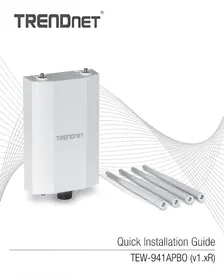
Quick Installation Guide
TEW-941APBO (v1.xR)
1 English
- Before You Start
- Quick Reference
- Hardware Installation and Configuration (Access Point Setup)
- Point to Point Bridge Setup and Configuration
- Waterproof Kit Installation
- Connecting the Grounding Wire
- Mounting
https://www.trendnet.com/qig/1420

30 Français
59 Español
https://www.trendnet.com/qig/1430

Package Contents
- TEW-941APBO
- Quick Installation Guide
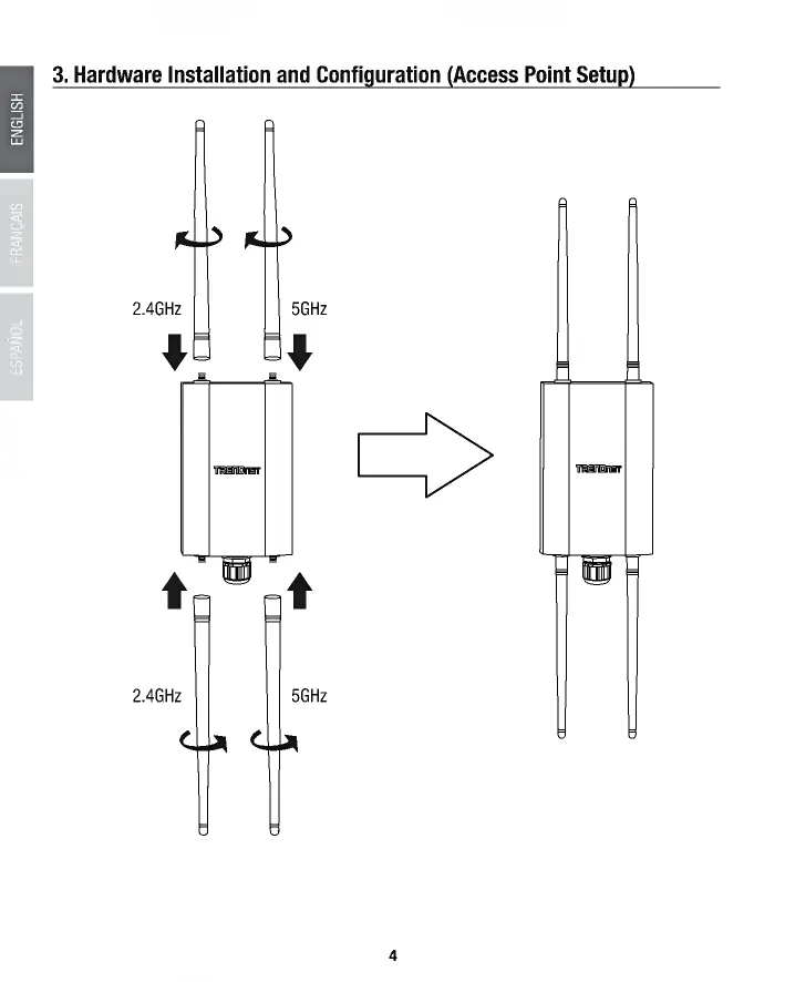
- 2 x Detachable 2.4GHz 5dBi antennas
- 2 x Detachable 5GHz 5dBi antennas
• IP67 weather rated cable gland - Mounting Hardware
Minimum Requirements
- Computer with a network port and web browser
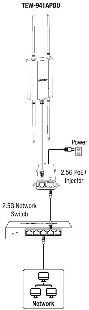
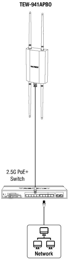
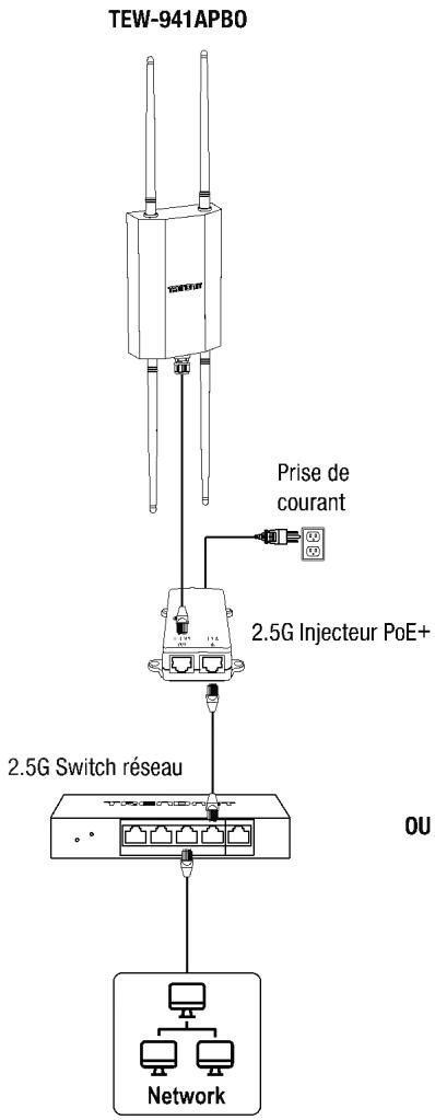
- A network switch or router with an available network 2.5G LAN PoE+ port or 2.5G PoE+ injector
- A PoE+ Network with an available LAN port connected to an existing network with Internet access and DHCP server for automatic IP addressing (required for setup with TRENDnet Hive Cloud Management only)
• RJ-45 network cables
Optional Equipment
- TRENDnet TPE-215GI (2.5G PoE+ Injector) for supplying both power and data over Ethernet to the access point if no PoE sourcing equipment is available
- Additional access point TRENDnet TEW-941APBO or TEW-940APBO (Optional for point-to-point bridging only)
- Power drill and Phillips bit or Phillips screwdriver for mounting
- Flat head bit or screwdriver for pole mounting clamp
Note: The access point complies with the IEEE 802.3at Power over Ethernet (PoE+) standard and can be used with other 802.3at PoE+ switches or PoE+ injectors to deliver both power and data to the access point through the network LAN (PoE) port.
IMPORTANT NOTE: The device does not have a hardware reset button. When changing the administrator password in the access point configuration page, please make sure to write down your new password.
2. Quick Reference
Note: By default, the wireless network name/SSID and wireless encryption settings have been pre-configured for your convenience and can be located on the included preset wireless setting sticker or on the device label located on the back of the access point. By default, the access point web management configuration page can be accessed using the URL http://tew-941apbo or using the default LAN IP address http://192.168.10.100. At default settings and initial setup, if the access point is connected to a network with a DHCP server providing IP address settings automatically, the access point will obtain IP address settings from the network DHCP server and if no DHCP server is available, the access point will use the default IP address settings 192.168.10.100 / 255.255.255.0. and you will need to manually configure your access point with the appropriate IP address and DNS server settings for Internet access. A network router is a typical DHCP server.
Preset Wireless Settings
Wi-Fi Name/SSID [AX/AC/N/A] TRENDnet941_5GHz_XXXX [AX/N/B/G] TRENDnet941_2.4GHz_XXXX
Wi-Fi Password 941XXXXXXXXX
Management Login
http://tew-941apbo username: admin password: admin
OR
3. Hardware Installation and Configuration (Access Point Setup)
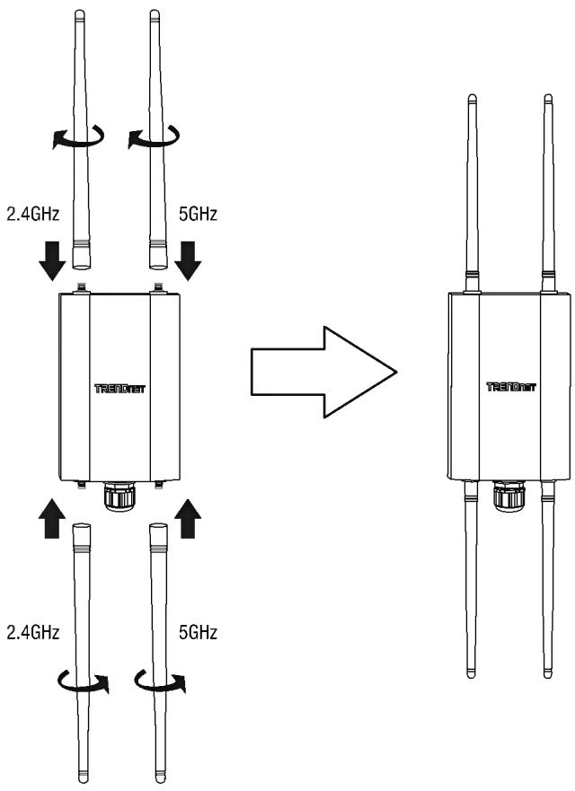
If you are configuring the access point to be managed from your existing TRENDnet Hive cloud account, please follow the steps in SECTION A. If you are configuring the access point for local network management only, please follow the steps in SECTION B.
SECTION A: Configuring the access point with TRENDnet Hive Cloud Management
Configuration with TRENDnet Hive Cloud Management requires an existing network with Internet access and DHCP server for automatic IP addressing. The access point must be configured to reach the Internet in order to connect to your TRENDnet Hive Management account.
It is strongly recommended to configure the access point first before mounting.
- Connect an Ethernet/network cable to your PoE+ switch and to your access point.
- Connect an Ethernet/network cable to your computer and one of the PoE+ switch ports.
- Connect another Ethernet/network cable to one of the PoE+ switch ports and your existing network with a Internet access and DHCP server for automatic IP addressing.
![graph TD A["TEW-941APBO"] -->|USB| B["2.5G PoE+ Switch"] B --> C["Router"] C --> D["Internet"] A -->|USB| E["2.5G PoE+ Switch"] E --> F["Router"] F --> G["Internet"]](/content/2025/12/338883/images/9c635a41e2d6c36a9dd43f21d99bb8072b523a86113afffba7e62d13df9578e6.jpg)
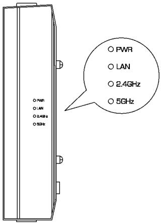
- The PWR, LAN, 2.4GHz, 5GHz LEDs will turn on to indicate that the access point is ready. Please refer to the LED definition table below.
| LED | Status | Description |
| PWR | Blinking | Device boot up |
| Solid Green | Device is operating normally | |
| LAN | Solid Green | 2.5G Data link established |
| Solid Orange | 1G Data link established | |
| Blinking | Data transmission | |
| 2.4GHz | Solid Green | 2.4GHz radio is enabled |
| Blinking | Data transmission | |
| 5GHz | Solid Green | 5GHz radio is enabled |
| Blinking | Data transmission |
-
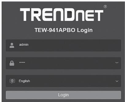
Select your language from the Language drop-down list and enter the User name and Password, and then click Login. By default:
-
User Name: admin
- Password: admin
- Click Next on the Setup Wizard. If the setup wizard does not appear, click the setup wizard button in the top right section of the access point management page to access the setup wizard.
Setup Wizard
This wizard will guide you through a step-by-step process to configure your AP and connect to the Internet
Next
Cancel
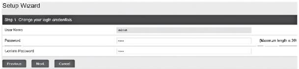
- You can change the access point administrator password by typing in the new password in the fields provided, then click Next. If entering a new password, please note that you will need to use the new password when logging into the access point management page for local access management moving forward.
IMPORTANT NOTE: The device does not have a hardware reset button. When changing the administrator password in the access point configuration page, please make sure to write down your new password.
- For the method of management, select TRENDnet Hive. After selecting TRENDnet Hive, click Next. Configuration with TRENDnet Hive Cloud Management requires an existing network with Internet access and DHCP server for automatic IP addressing. The access point must be configured to reach the Internet in order to connect to your TRENDnet Hive Cloud Management account. If the access point is unable to obtain IP address settings and DNS from the DHCP server and unable to reach the Internet, registration of the access point to your TRENDnet Hive cloud management account will fail.

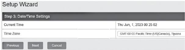
- Select your Time Zone, then click Next.
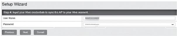
- Enter the user account credentials for your TRENDnet Hive Cloud Management account to register the access point with your account, then click Next.
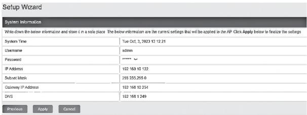
- The summary page will display all of the configuration settings that were applied through the setup wizard. Click Apply to complete the setup wizard. Please note the new password and IP settings for local access management to the access point.
- To verify the access point is now successfully registered with your TRENDnet Hive Cloud Management account, the Hive button in the top right will be green to indicate successful registration.

SECTION B: Configuring the access point for local network management
It is strongly recommended to configure the access point first before mounting.
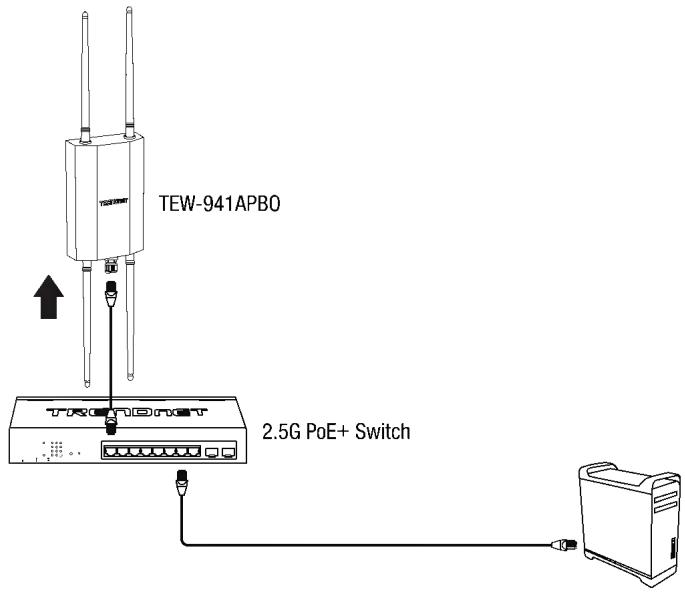
- Connect a network cable from a PoE+ switch to your access point.
- Connect an Ethernet/network cable to your computer and one of the PoE+ switch ports.
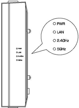
- The PWR, LAN, 2.4GHz, 5GHz LEDs will turn on to indicate that the access point is ready. Please refer to the LED definition table below.
| LED | Status | Description |
| PWR | Blinking | Device boot up |
| Solid Green | Device is operating normally | |
| LAN | Solid Green | 2.5G Data link established |
| Solid Orange | 1G Data link established | |
| Blinking | Data transmission | |
| 2.4GHz | Solid Green | 2.4GHz radio is enabled |
| Blinking | Data transmission | |
| 5GHz | Solid Green | 5GHz radio is enabled |
| Blinking | Data transmission |
-
Assign a static IP address to your computer's network adapter in the subnet of 192.168.10.x (e.g. 192.168.10.25) and subnet mask of 255.255.255.0. For more information on assigning a static IP address to your computer's network adapter, please refer to item Q1 in the last section of the installation guide, Installation Tips and Troubleshooting.
-
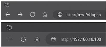
Open your web browser, type the default URL http://tew-941abpo or default IP address http://192.168.10.100 of the wireless access point in the address bar and then press Enter.
-
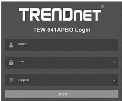
Select your language from the Language drop-down list and enter the User name and Password, and then click Login. By default:
-
User Name: admin
- Password: admin
- Click Next on the Setup Wizard. If the setup wizard does not appear, click the setup wizard button in the top right section of the access point management page to access the setup wizard.
Setup Wizard
This wizard will guide you through a step-by-step process to configure your AP and connect to the Internet
Next
Cancel
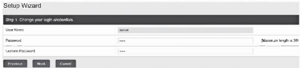
- You can change the access point administrator password by typing in the new password in the fields provided, then click Next. If entering a new password, please note that you will need to use the new password when logging into the access point management page for local access management moving forward.
IMPORTANT NOTE: The device does not have a hardware reset button. When changing the administrator password in the access point configuration page, please make sure to write down your new password.
- For the method of management, select Default Management, click Next.

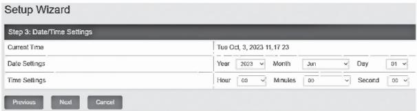
- Configure the access point date and time settings, click Next.
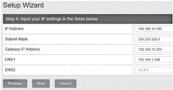
- Configure the access point IP address, subnet mask, gateway IP address, and DNS settings to match the requirements of your existing network using the fields provided, then click Next.
Note: This step will configure static IP address settings on your access point. If the access point IP address settings are changed to a different IP network subnet such as 192.168.1.x, 192.168.2.x, etc. your computer's network adapter settings will need to be changed to match the new IP address settings configured on the access point in order to access the access point management page.
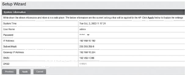
- The summary page will display all of the configuration settings that were applied through the setup wizard. Click Apply to complete the setup wizard. Please note the new password and IP settings for local access management to the access point.
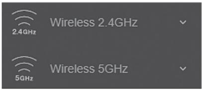
- To configure your wireless network name/SSID and wireless encryption settings, click the wireless band you would like to configure Wireless 2.4GHz or Wireless 5GHz and click on Wireless Network. By default, the wireless network name/SSID and wireless encryption have been pre-configured for your convenience and can be located on the included wireless settings sticker or on the device label located on the back of the access point. If you are modifying the wireless settings, you will need to connect to the access point with your WiFi client using the new settings.
- In the Current Profiles, in the first entry, you can enter a new SSID, change the Security Mode and WiFi Password. Click Apply at the bottom of the page.

- In the top right main menu, click on the Save button to commit the configuration changes.
Important Note: Configuration changes in the access point web management page are not applied until you click the Save button. This allows you to make multiple configuration changes and apply multiple changes all at the same time. Additionally, you can click the Save button on the left side to view pending unsaved configuration changes.
- After you have completed the access point configuration, reconfigure your computer's network adapter back to the original settings to obtain IP address settings automatically using DHCP, or enter the IP settings.
For more information on reconfiguring your computer's network adapter to obtain IP address settings automatically using DHCP, please refer to item Q2 in the last section of the installation guide, Installation Tips and Troubleshooting.
4. Point to Point Bridge Setup and Configuration
Note:
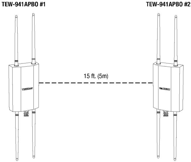
- The initial configuration should be completed in a testing environment with the TEW-941APBO and additional access point TEW-941APO or TEW-940APBO approximately 15ft. (5 m) apart from one another. If using the TEW-940APBO directional access point, the front panel should be directly facing the TEW-941APBO.
- It is strongly recommended to configure and connect the access points before mounting.
- In this example, we will configure the TEW-941APBO 5GHz Wireless settings and configure an additional TEW-941APBO or TEW-940APBO to create a wireless bridge to the first access point on the 5GHz Wireless band.
Phase 1: Overview
In this installation guide, we will assume the following:
Router Settings
Default Gateway IP address: 192.168.10.1
Subnet Mask: 255.255.255.0
TEW-941APB0 #1
IP Address: 192.168.10.50
Subnet Mask: 255.255.255.0
Default Gateway: 192.168.10.1
Primary DNS: 1.1.1.1
Operation Mode: Access Point
Wireless Security: WPA3-SAE AES Encryption
TEW-941APBO #2 or TEW-940APBO
IP Address: 192.168.10.51
Subnet Mask: 255.255.255.0
Default Gateway: 192.168.10.1
Primary DNS: 1.1.1.1
Operation Mode: Client Bridge
Wireless Security: WPA3-SAE AES Encryption
Phase 2: Configure the TEW-941APBO #1 Settings
Note: The predefined wireless configuration settings may be used found on the included wireless sticker, device label, or follow the configuration steps to below to manually configure a specific wireless SSID and password for the wireless bridge.
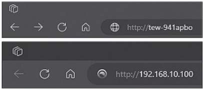
- Open your web browser, type the default URL http://tew-941abpo or default IP address http://192.168.10.100 of the wireless access point in the address bar and then press Enter.
-
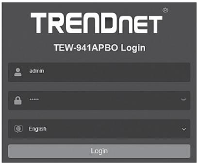
Select your language from the Language drop-down list and enter the User name and Password, and then click Login. By default:
-
User Name: admin
- Password: admin
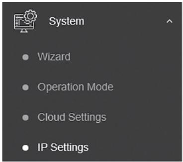
- In the left navigation menu, click System and IP Settings.
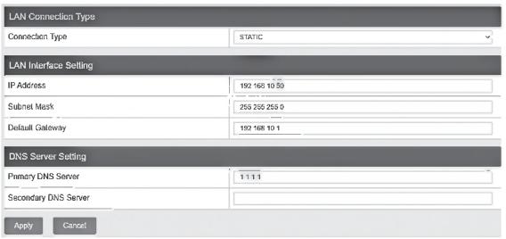
- Click the Connection Type drop-down list and select STATIC, and enter the IP Address 192.168.10.50, Subnet Mask 255.255.255.0, Default Gateway 192.168.10.1, and Primary DNS Server 1.1.1.1, then click Apply.
Note: You will need to log back into the access point management page using the new IP address settings.
- In the left navigation menu, click Wireless 5GHz and Wireless Network.
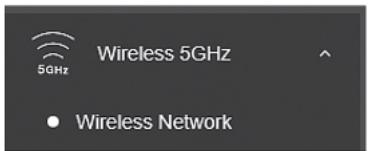
- For the first entry that pre-configured, click Edit in the right column.
| Current Profiles | |||||
| Index | Scotus | SSID | Security Mode | Password | Edit / Add |
| 1 | Enabled | TRENDex3LX_MSH_ASP4 | WPA2:PS4WVPA3:GAE Nasi AES | Edit | |
- At the top under Wireless Settings, you can change the default SSID in the SSID field.
Note: Please note the SSID as it will be needed to connect the second access point to create the wireless bridge.

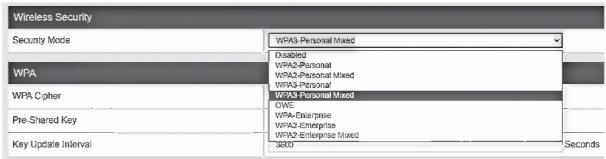
- Under the Wireless Security section, click the drop-down to select the wireless security mode to use.
Note: For general wireless client device compatibility, it is recommended to use WPA3-Personal Mixed AES. For wireless bridging with an additional TEW-941APBO or TEW-940APBO, it is recommended to use the highest supported WPA3-Personal AES.
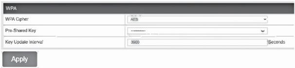
- Enter the WiFi Password or Pre-Shared Key in the Pre-Shared Key field and click Apply at the bottom of the page. (8-63 alphanumeric characters)
Note: Please make note of the WiFi password or pre-shared key assigned as it will be used for the configuration of the second access point to make the wireless bridge.
- In the top right main menu, click on the Save button to commit the configuration changes.
Phase 3: Configure the TEW-941APBO #2 or TEW-940APBO Settings
When configuring the second TEW-941APBO access point or TEW-940APBO, repeat 1-3 of the steps in Phase 2: Configure the TEW-941APBO #1 Settings.
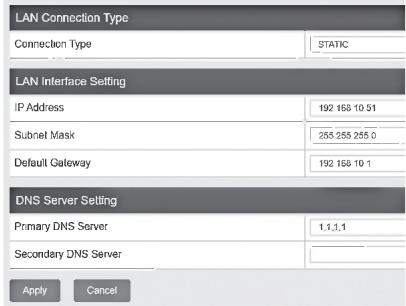
- In Step 4, click the Connection Type drop-down list and select STATIC, and enter the IP Address 192.168.10.51, Subnet Mask 255.255.255.0, Default Gateway 192.168.10.1, and Primary DNS Server 1.1.1.1, then click Apply.
Note: You will need to log back into the access point management page using the new IP address settings.
- In the left navigation menu, click System and Operation Mode.
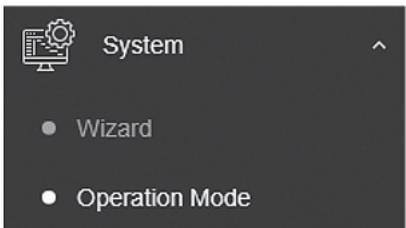
- Click Operation Mode drop-down list and select Client Bridge, then click Apply.
Note: If using the TEW-940APBO, the field will be named 5GHz Operation Mode.

- In the left navigation menu, click Wireless 5GHz and Wireless Network.
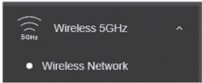
- In the Wireless Network section, click on Site Survey.

- In the Site Survey list, find the SSID configured on the first access point TEW-941APBO and select it by clicking on the entry.
| S50 | S550 | Channel | Signal Level | Type | Security | Notes |
| TRENDexHL_90HJ_A2F6 | DC 12:55-A2F62 | 48 | -25 dBm | RASAHESE | WHA-SDF mixed | HP |
| TRENDexHL_92HJ_90HJ | DB 8:57 DC 9B 52 | 141 | -25 dBm | MAC VERTO | WENA-FIX4 | HP |
| TRENDexHL_92HJ_90HJ | DB 8:57 23-04-03 | 157 | -25 dBm | MAC VERTO | WENA-FIX4 | HP |
- The details of the selected SSID will be entered in to the wireless section automatically. Under the Wireless Security section under WPA, enter the Pre-Shared Key configured on the first access point and click Apply.
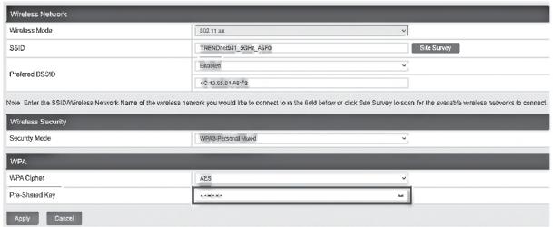
- In the top right main menu, click on the Save button to commit the configuration changes.
Phase 4: Confirm Connectivity
- Leave your computer connected to TEW-941APBO #2 or TEW-940APBO and keep the access point configuration page open.
- Make sure both TEW-941APBO #1 and TEW-941APBO #2 access points are powered on approximately 15 ft. (5 m) apart from one another.
- To verify connectivity, in the TEW-941APBO #2 or TEW-940APBO access point configuration page, click Management and click Diagnostics. Under the Ping Test Parameter section, enter the IP Address of the TEW-941APBO #1, 192.168.10.50, then click Ping.
| Ping Test Parameter | |
| IP Address | 192.168.10.50 |
| Packet Length | 64 |
| Number of Pings | 4 |
- Ping replies and 0% packet loss will indicate a successful point to point bridge connection between the TEW-941APBO #1 and TEW-941APBO #2 or TEW-940APBO access points.
Note: If the connectivity test fails, wait for about 1 minute and try again. Make sure there are no obstacles between the two access points when running the connectivity test and make sure the access points are not too close together.
Diagnostics Result
PING 192.168.10.50 (192.168.10.50): 64 data bytes
72 bytes from 192.168.10.50: seq=0 ttl=64 time=4.873 ms
72 bytes from 192.168.10.50: seq=1 ttl=64 time=4.072 ms
72 bytes from 192.168.10.50: seq=2 ttl=64 time=4.104 ms
72 bytes from 192.168.10.50: seq=3 ttl=64 time=4.136 ms -- 192.168.10.50 ping statistics --
4 packets transmitted, 4 packets received, 0% packet loss round-trip min/avg/max = 4.072/4.296/4.873 ms
5. Waterproof Kit Installation
Note: The waterproof kit can only be installed with non-terminated Ethernet cabling. The Ethernet cable can be properly terminated after installing the waterproof kit.
- Unscrew the sealing nut from the main body of the access point.
- Separate the rubber seal from the claw.
- Verify that you have the following parts:

- Insert one end of an Ethernet cable into the sealing nut.
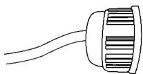
- Insert the Ethernet cable into the seal.
Note: After the non-terminated Ethernet cable is installed through the sealing nut, claw and seal, the cable may be properly terminated.
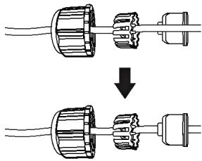
- Insert the seal into the claw.
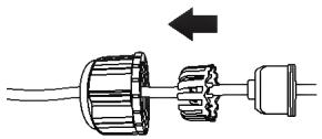
- Insert the seal/rubber claw into the Cable Gland.
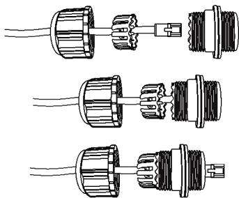
- Connect the Ethernet cable to the 2.5G LAN PoE+ port on the bottom of the access point.
- By hand, screw the main body counter clockwise to secure it to the access point.
- By hand, screw the seal nut clockwise to secure it to the main body.
6. Connecting the Grounding Wire
- Identify the grounding point on the back of the access point.
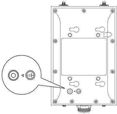
- Align one end of the grounding wire over the grounding point and secure the grounding wire with the provided screw and washers turning clockwise
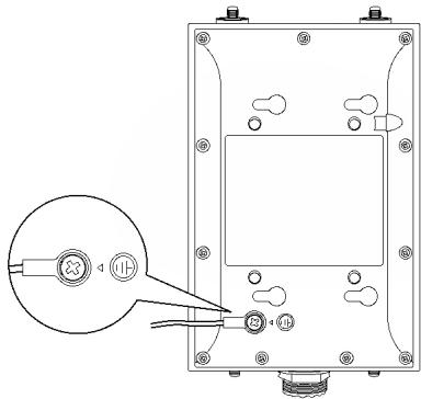
- Connect the other end of the grounding wire to a grounded object. (e.g. earth driven rod, grounding electrical system)
7. Mounting
- Install the metal mounting bracket by aligning the four bracket points to the four mounting holes on the back of the access point. The hole for the mount bracket locking screw should be located at the top right when installing the mounting bracket to the access point.
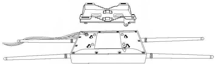
- After installing the mounting bracket to the back of the access point, slide the mounting bracket left and install the locking screw by turning clockwise.
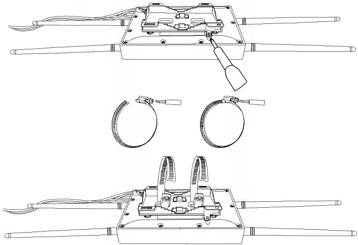
Note: If mounting the TEW-940APBO with directional antenna, please make sure that the access point is mounted with the same vertical height, within line of sight, and facing the direction of the TEW-941APBO to allow for the optimal connectivity.
Completed Installation Reference
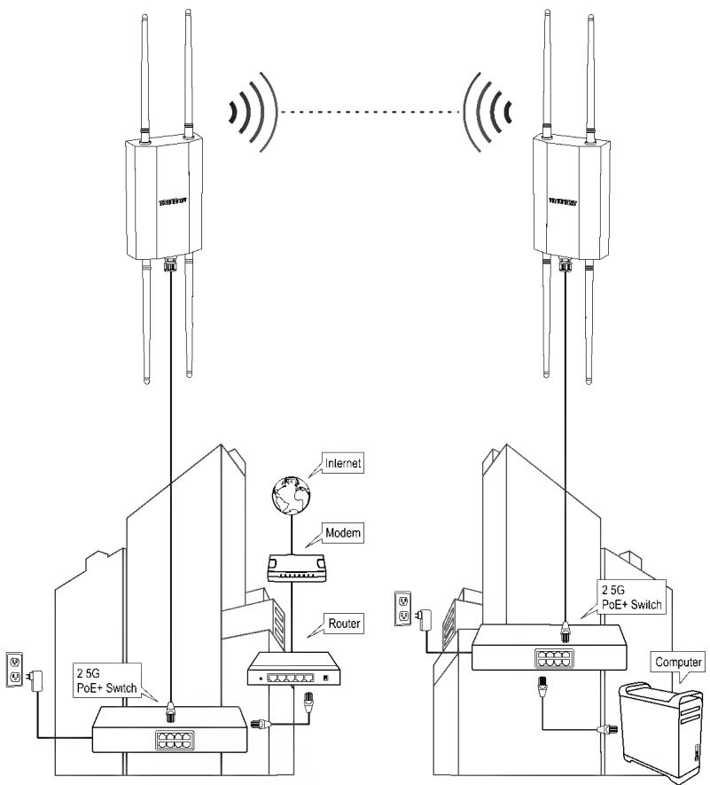
Building 1
Building 2
http://tew-941apbo username: admin password: admin
This wizard will guide you through a step-by-step process to configure your AP and connect to the Internet.
Next
Cancel
This wizard will guide you through a step-by-step process to configure your AP and connect to the Internet.
Next
Cancel
72 bytes from 192.168.10.50: seq=0 ttl=64 time=4.873 ms
72 bytes from 192.168.10.50: seq=1 ttl=64 time=4.072 ms
72 bytes from 192.168.10.50: seq=2 ttl=64 time=4.104 ms
72 bytes from 192.168.10.50: seq=3 ttl=64 time=4.136 ms
-- 192.168.10.50 ping statistics --
4 packets transmitted, 4 packets received, 0% packet loss
round-trip min/avg/max = 4.072/4.296/4.873 ms
This wizard will guide you through a step-by-step process to configure your AP and connect to the Internet
Next
Cancel
TEW-941APBO #2 o TEW-940APBO
TEW-941APBO #2
15 ft. (5m)
72 bytes from 192.168.10.50: seq=0 ttl=64 time=4.873 ms
72 bytes from 192.168.10.50: seq=1 ttl=64 time=4.072 ms
72 bytes from 192.168.10.50: seq=2 ttl=64 time=4.104 ms
72 bytes from 192.168.10.50: seq=3 ttl=64 time=4.136 ms
-- 192.168.10.50 ping statistics --
4 packets transmitted, 4 packets received, 0% packet loss
round-trip min/avg/max = 4.072/4.296/4.873 ms
Q1: How do I configure my computer's network adapter with a static IP address?
Note: Please note that although the following procedures are provided to follow for your operating system network adapter settings to be used as general guidelines, however, it is strongly recommended that you consult your computer or operating system manufacturer directly for assistance on the proper procedure for configuring network settings. If you are experiencing difficulties, please contact your computer or operating system manufacturer for assistance.
Windows 2000/XP/Vista/7/8/8.1/10/11
- On your keyboard, press Windows Logo + R keys simultaneously to bring up the Run dialog box.
- In the dialog box, type ncpa.cpl to bring up the Network Connections window.
- Right-click the Local Area Connection or Ethernet icon, click Properties, and double-click Internet Protocol Version 4 (TCP/IPv4).
- Then click Use the following IP address and assign your network adapter a static IP address. See example static IP address settings below.
• IP address: 192.168.10.25 -
Subnet mask: 255.255.255.0
-
Click OK on both TCP/IPv4 Properties and Local Area Connection Properties windows.
MAC OS X
- From the Apple drop-down list, select System Preferences.
- Click the Network icon.
- From the Location drop-down list, select Automatic.
-
Select and view your Ethernet connection.
-
For MAC OS 10.4, from the Show drop-down list, select Built-in Ethernet and select the TCP/IP tab.
-
For MAC OS 10.5 and above, in the left column, select Ethernet.
-
Configure TCP/IP to use a static IP.
- From the Configure IPv4 or Configure drop-down list, select Manually and assign your network adapter a static IP address. Then click the Apply or Apply Now button. See example static IP address settings below.
• IP address: 192.168.10.25
- Subnet mask: 255.255.255.0
- You may be prompted to restart your computer to apply the new IP address settings.
Q2: I configured my computer's network adapter with a static IP address, how do I reconfigure my computer's network adapter to default settings and obtain an IP address automatically using DHCP?
Note: Please note that although the following procedures are provided to follow for your operating system network adapter settings to be used as general guidelines, however, it is strongly recommended that you consult your computer or operating system manufacturer directly for assistance on the proper procedure for configuring network settings. If you are experiencing difficulties, please contact your computer or operating system manufacturer for assistance.
Windows 2000/XP/Vista/7/8/8.1/10/11
- On your keyboard, press Windows Logo + R keys simultaneously to bring up the Run dialog box.
- In the dialog box, type ncpa.cpl to bring up the Network Connections window.
- Right-click the Local Area Connection or Ethernet icon, click Properties, and double-click Internet Protocol Version 4 (TCP/IPv4).
- Then click Obtain an IP address automatically and Obtain DNS server address automatically.
- Click OK on both TCP/IPv4 Properties and Local Area Connection Properties windows.
MAC OS X
- From the Apple drop-down list, select System Preferences.
- Click the Network icon.
- From the Location drop-down list, select Automatic.
-
Select and view your Ethernet connection.
-
In MAC OS 10.4, from the Show drop-down list, select Built-in Ethernet and select the TCP/IP tab.
• In MAC OS 10.5 and above, in the left column, select Ethernet. -
Configure TCP/IP to use a static IP.
- From the Configure IPv4 or Configure drop-down list, select Using DHCP and click the Apply or Apply Now button.
- You may be prompted to restart your computer to apply the new IP address settings.
Q3: I typed http://192.168.10.100 in my Internet Browser Address Bar, but an error message says "The page cannot be displayed." How can I access the wireless access point management page?
- Double check all physical cable and port connections.
- Make sure the PWR/LAN/2.4GHz/5GHz LEDs on the wireless access point front panel are on.
- Make sure your computer's network adapter is configured with a static IP address. (Refer to Q1 for instructions on assigning a static IP address).
- Make sure your computer is connected to the access point network LAN port and LAN LED is on.
- Since the access point default IP address is 192.168.10.100, make sure there are no other network devices assigned an IP address of 192.168.10.100
Note: After checking all of the recommended items above, please attempt to access the wireless access point management page again.
Q4: How do I find the current IP address of my computer's network adapter?
Note: Please note that although the following procedures are provided to follow for your operating system network adapter settings to be used as general guidelines, however, it is strongly recommended that you consult your computer or operating system manufacturer directly for assistance on the proper procedure for configuring network settings. If you are experiencing difficulties, please contact your computer or operating system manufacturer for assistance.
Command Prompt Method
Windows 2000/XP/Vista/7/8/8.1/10/11
- On your keyboard, press Windows Logo + R keys simultaneously to bring up the Run dialog box.
- In the dialog box, type cmd to bring up the command prompt.
- In the command prompt, type ipconfig /all to display your IP address settings.
MAC OS X
- Navigate to your Applications folder and open Utilities.
- Double-click on Terminal to launch the command prompt.
- In the command prompt, type ipconfig getifaddr
to display the wired or wireless IP address settings.
Note: en0 is typically the wired Ethernet and en1 is typically the wireless Airport interface.
Graphical Method
Windows XP/Vista/7/8/8.1/10/11
- On your keyboard, press Windows Logo + R keys simultaneously to bring up the Run dialog box.
- In the dialog box, type ncpa.cpl to bring up the Network Connections window.
- Double-click the Local Area Connection icon and click the Details button to view the current IP address settings.
Note: The computer's network adapter must be enabled and connected to view the current IP address settings.
MAC OS X
- From the Apple menu, select System Preferences.
- In System Preferences, from the View menu, select Network.
- In the Network preference window, click a network port (e.g., Ethernet, AirPort, modem). If you are connected, you'll see your IP address settings under "Status:"
This device complies with Part 15 of the FCC Rules. Operation is subject to the following two conditions: (1) This device may not cause harmful interference, and (2) this device must accept any interference received, including interference that may cause undesired operation.
This equipment has been tested and found to comply with the limits for a Class B digital device, pursuant to Part 15 of the FCC Rules. These limits are designed to provide reasonable protection against harmful interference in a residential installation. This equipment generates, uses and can radiate radio frequency energy and, if not installed and used in accordance with the instructions, may cause harmful interference to radio communications. However, there is no guarantee that interference will not occur in a particular installation. If this equipment does cause harmful interference to radio or television reception, which can be determined by turning the equipment off and on, the user is encouraged to try to correct the interference by one of the following measures:
- Reorient or relocate the receiving antenna.
- Increase the separation between the equipment and receiver.
- Connect the equipment into an outlet on a circuit different from that to which the receiver is connected.
- Consult the dealer or an experienced radio/TV technician for help.
FCC Caution: Any changes or modifications not expressly approved by the party responsible for compliance could void the user's authority to operate this equipment.
This transmitter must not be co-located or operating in conjunction with any other antenna or transmitter.
IMPORTANT NOTE:
Radiation Exposure Statement:
This equipment complies with FCC radiation exposure limits set forth for an uncontrolled environment. This equipment should be installed and operated with minimum distance 20cm between the radiator & your body.
This radio transmitter FCC ID: XU8TEW941APBO has been approved by FCC to operate with antenna types listed below with the maximum permissible gain and required antenna impedance for each antenna type indicated. Antenna types not included in this list, having a gain greater than the maximum gain indicated for that type, are strictly prohibited for use with this device.
Antenna list
| No. | Manufacturer | Part No. | Antenna Type | Peak Gain |
| 1 | Master Wave | 98143MRSX000 | Dipole | 5.17dBi |
| 2 | Master Wave | 98143URSX000 | Dipole | 5.17dBi |
Certifications
This device complies with Part 15 of the FCC Rules.
Operation is subject to the following two conditions:
(1) This device may not cause harmful interference.
(2) This device must accept any interference received. Including interference that may cause undesired operation.


Waste electrical an electronic products must not be disposed of with household waste. Please recycle where facilities exist. Check with your Local Authority or Retailer for recycling advice.
Applies to PoE Products Only: This product is to be connected only to PoE networks without routing to the outside plant
Note
The Manufacturer is not responsible for any radio or TV interference caused by unauthorized modifications to this equipment. Such modifications could void the user's authority to operate the equipment
Advertencia
If you have any questions regarding the product installation, please contact our Technical Support.
Toll free US/Canada: 1-855-373-4741
Regional phone numbers available
at www.trendnet.com/support
TRENDnet
20675 Manhattan Place
Torrance, CA 90501
USA
Product Warranty Registration
Please take a moment to register your product online. Go to TRENDnet's website at:
www.trendnet.com/register
- 1 ENGLISH
- 30 FRANÇAIS
- 59 ESPAÑOL
- PACKAGE CONTENTS
- MINIMUM REQUIREMENTS
- OPTIONAL EQUIPMENT
- QUICK REFERENCE
- PRESET WIRELESS SETTINGS
- HARDWARE INSTALLATION AND CONFIGURATION (ACCESS POINT SETUP)
- SECTION A: CONFIGURING THE ACCESS POINT WITH TRENDNET HIVE CLOUD MANAGEMENT
- SETUP WIZARD
- SECTION B: CONFIGURING THE ACCESS POINT FOR LOCAL NETWORK MANAGEMENT
- POINT TO POINT BRIDGE SETUP AND CONFIGURATION
- NOTE
- PHASE 1: OVERVIEW
- ROUTER SETTINGS
- TEW-941APB0 #1
- TEW-941APBO #2 OR TEW-940APBO
- PHASE 2: CONFIGURE THE TEW-941APBO #1 SETTINGS
- PHASE 3: CONFIGURE THE TEW-941APBO #2 OR TEW-940APBO SETTINGS
- PHASE 4: CONFIRM CONNECTIVITY
- DIAGNOSTICS RESULT
- WATERPROOF KIT INSTALLATION
- CONNECTING THE GROUNDING WIRE
- MOUNTING
- TEW-941APBO #2 O TEW-940APBO
- Q1: HOW DO I CONFIGURE MY COMPUTER'S NETWORK ADAPTER WITH A STATIC IP ADDRESS
- WINDOWS 2000/XP/VISTA/7/8/8.1/10/11
- MAC OS X
- Q2: I CONFIGURED MY COMPUTER'S NETWORK ADAPTER WITH A STATIC IP ADDRESS, HOW DO I RECONFIGURE MY COMPUTER'S NETWORK ADAPTER TO DEFAULT SETTINGS AND OBTAIN AN IP ADDRESS AUTOMATICALLY USING DHCP
- Q3: I TYPED HTTP://192.168.10.100 IN MY INTERNET BROWSER ADDRESS BAR, BUT AN ERROR MESSAGE SAYS "THE PAGE CANNOT BE DISPLAYED." HOW CAN I ACCESS THE WIRELESS ACCESS POINT MANAGEMENT PAGE
- Q4: HOW DO I FIND THE CURRENT IP ADDRESS OF MY COMPUTER'S NETWORK ADAPTER
- COMMAND PROMPT METHOD
- GRAPHICAL METHOD
- WINDOWS XP/VISTA/7/8/8.1/10/11
- IMPORTANT NOTE
- RADIATION EXPOSURE STATEMENT
- CERTIFICATIONS
- ADVERTENCIA
- TRENDNET
- PRODUCT WARRANTY REGISTRATION
Brand : TRENDNET
Model : TEW-941APBO (v1.xR)
Category : Access Point