USER MANUAL HPG25 - HPG40 - HPG50 - HPG70 GRE
INDEX FOR DIFFERENT LANGUAGES
English manual. 1~31
Manual en Espanol 32~63
Notice en Francais. 64~97
Deutsches Handbuch. 98~129
Manuale Italiano. 130~163
Manual Português. 164~195
Netherland manual. 196~227
Polskiej firmy. 228~267
Warranty. 268-274
| This symbol shows that information is available such as the Operating Manual or Installation Manual. | This symbol shows that this appliance uses R32, a low burning velocity refrigerant. |
| This symbol shows that the Operation Manual should be read carefully. | This symbol shows that service personnel should be handling this equipment with reference to the Installation Manual. |
GENERALWARNINGS
- Failure to respect the warnings may cause serious damage to the pool equipment or cause serious injury, even death.
- Only a person qualified in the technical fields concerned (electricity, hydraulics or refrigeration) is authorised to carry out maintenance or repair work on the appliance. The qualified technician working on the appliance must use/wear personal protective equipment (such as safety goggles and protective gloves, etc.) in order to reduce the risk of injury occurring when working on the appliance.
- Before handling the appliance, check that it is switched off and isolated.
- This appliance is not intended for use by individuals (including children, over the age of 8) lacking in experience or with impaired physical, sensory or mental capabilities, unless: they receive supervision and are instructed on how to use the appliance by a person responsible for their safety; and if they understand the hazards involved.
Children must be supervised to ensure that they do not play with the appliance.
- The appliance must be installed according to the manufacturer's instructions and in compliance with local and national standards. The installer is responsible for installing the appliance and for compliance with national installation regulations. Under no circumstances may the manufacturer be held liable in the event of failure to comply with applicable local installation standards.
- For any work other than the simple user maintenance described in this manual, the product should be referred to as qualified professional.
- Incorrect installation and/or use may cause serious damage to property or serious injuries (possibly causing death).
- If the appliance suffers a malfunction, do not try to repair it yourself; instead contact a qualified technician.
- Deactivating, eliminating or by-passing any of the safety mechanisms integrated into the appliance shall automatically void the warranty, in addition to the use of spare parts manufactured by unauthorised third-party manufacturers.
- Do not spray insecticide or any other chemical (flammable or non-flammable) in the direction of the appliance, as this may damage the body and cause a fire.
- Do not touch the fan or moving parts and do not place objects or your fingers in the vicinity of the moving parts when the appliance is in operation. Moving parts can cause serious injury or even death.
-
Please keep the display controller in a dry area, or well close the insulation cover to protect the display controller from being damaged by humidity.
-
The power supply to the appliance must be protected by a dedicated 30mA Residual Current Device (RCD), complying with the standards and regulations in force in the country in which it is installed.
- Do not use any extension lead when connecting the appliance; connect the appliance directly to a suitable power supply.
-
Before carrying out any operations, check that:
-
The voltage indicated on the appliance information plate corresponds to the mains voltage.
- The power grid must be adapted to the power requirements of the appliance, and is grounded.
- The plug (where applicable) is suitable for the socket.
- Do not disconnect and reconnect the appliance to the power supply when in operation.
- Do not pull on the power cord to disconnect it from the power supply.
- If the power cord is damaged, it must be replaced by the manufacturer, its technician or a qualified person to guarantee safety.
- Do not perform maintenance or servicing operations on the appliance with wet hands or if the appliance is wet.
- Before connecting the appliance to the power supply, check that the connection unit or socket to which the appliance will be connected is in good condition and shows no signs of damage or rust.
- In stormy weather, disconnect the appliance from the power supply to prevent it from suffering lightning damage. Do not immerse the appliance in water or mud.
WARNING CONCERNING APPLIANCES CONTAINING REFRIGERANT R32
- R32 refrigerant is classed under category A2L as mildly flammable.
- Do not release R32 fluid into the atmosphere. These are fluorinated greenhouse gases, covered by the Kyoto Protocol, with a Global Warming Potential (GWP) of 675 (European regulation EU 517/2014).
- The appliance must be stored in a well-ventilated location away from all ignition sources.
- Install the unit outdoors. Do not install the unit indoors or in an enclosed and non-ventilated outdoor location.
- Do not use means for accelerating the defrosting or cleaning process other than those recommended by the manufacturer.
- The appliance must be stored in a room without any permanent ignition source (such as open flames, operating gas appliance or operating electric heating).
- Do not perforate or incinerate.
- Please note that R32 refrigerant may give off a certain odour.
- In order to comply with the applicable standards and regulations in terms of the environment and installation, in particular French decree No. 2015-1790 and/or European regulation EU 517/2014, a leak test must be performed on the cooling circuit at least once a year. This operation must be carried out by a specialist certified to test cooling appliances.
- Please keep the display controller in a dry area, or well close the insulation cover to protect the display controller from being damaged by humidity.
MAINTENANCE:WARNINGS CONCERNING APPLIANCES CONTAINING R32 REFRIGERANT
- When servicing the appliance, the composition and state of the heat transfer fluid must be checked, as well as the absence of any traces of refrigerant.
- During the annual appliance sealing test in accordance with applicable legislation, the high and low pressure switches must be checked to ensure that they are securely fastened to the refrigerant circuit and that they cut off the electrical circuit when tripped.
- During maintenance work, ensure there are no traces of corrosion or oil around the cooling components.
-
Do not braze or weld the pipe if there is refrigerant inside machine. Please do not charge the gas when in a confined space.
-
Before starting work on systems containing flammable refrigerants, safety checks must be carried out to guarantee a minimal ignition risk.
Work procedure
- The work must be carried out according to a controlled procedure in order to reduce the risks of releasing a flammable gas or vapour while working.
- Before beginning work on the cooling circuit, stop the appliance and wait for a few minutes before fitting the temperature and pressure sensors. Some elements such as the compressor and piping may reach temperatures in excess of 100ircC and high pressures with the consequent risk of severe burns.
General work area
- All maintenance staff and other personnel working in the surrounding area must be made aware of the work carried out. Work conducted in enclosed areas must be avoided.
Check for the presence of refrigerant
- The area must be analysed using a suitable refrigerant detector before and during work so that the technician is informed of the presence of a potentially toxic or flammable atmosphere. Check that the leak detection equipment used is suitable for use with all refrigerants concerned, i.e. that it does not cause a spark, is correctly isolated or is entirely safe.
Check for the presence of a fire extinguisher
- If work must be carried out on the cooling equipment or any part associated therewith at a certain temperature, suitable fire extinguishing means must be within reach. Place a dry chemical fire extinguisher or CO2 fire extinguisher near the work area.
No source of ignition
- No person carrying out work on a cooling system involving exposing the piping may use any ignition source, which could create a fire or explosion risk. All possible ignition sources, in particular cigarettes, must not enter within a sufficient perimeter of the installation, repair, removal or disposal site, in the event that refrigerant could be released into the surrounding space. Before starting the work, the area around the equipment must be examined to check for all fire or ignition risks. "No smoking" signs must be displayed.
Area ventilation
- Before accessing the unit in any manner whatsoever with the intention of performing any maintenance task, check that the area is open and well-ventilated. Suitable ventilation must be provided throughout the maintenance task to allow any refrigerant that could be released into the atmosphere to be safely dispersed.
Refrigeration equipment check
- The manufacturer's recommendations in terms of care and maintenance must always be complied with. When replacing electric components, check that components used are of the same type and category as those recommended/approved by the manufacturer. When in doubt, contact the manufacturer's technical department for assistance.
-
The following checks must be applied to installations using flammable refrigerants:
-
the markings on the equipment must remain visible and legible; any illegible markings or signs must be rectified;
-
the hoses or components of the cooling circuit are installed in a position where they are unlikely to be exposed to any substance capable of corroding the components containing refrigerant, unless the components are made from materials that are typically corrosion-proof or correctly protected from such corrosion.
Electric component check
- The repair and maintenance of electric components must include initial safety checks and component inspection procedures. If a defect capable of jeopardising safety arises, no power supply must be connected to the circuit until the problem has been completely resolved. If the defect cannot be rectified immediately and if maintenance work must continue, an appropriate temporary solution must be found. This must be reported to the equipment's owner so that all persons concerned are made aware.
-
The repair and maintenance of electric components must include the following initial safety checks:
-
the capacitors are discharged: this must be carried out safely to prevent all risks of ignition;
-
no electric component or live wiring is exposed while charging, overhauling or draining the system;
-
the system must be grounded at all times.
Repair of insulated components
- When repairing insulated components, all power sources must be disconnected from the equipment on which the work is being carried out before removing the insulating cover, etc. If the equipment must be powered during maintenance work, a leak detector must continuously monitor for leaks at the most critical point in order to report any potentially hazardous situation.
- Particular attention must be paid to the following points to ensure that, when performing work on the electric components, the housing is not altered to the point of affecting the protection rating. This includes damaged wires, an excessive number of connections, terminals that do not comply with the original specifications, damaged seals, incorrect installation of the cable glands, etc.
- Make sure that the appliance is properly fixed.
- Make sure that the seals or insulating materials are not deteriorated to the point that they no longer prevent a flammable atmosphere from penetrating the circuit. Spare parts must be compliant with the manufacturer's specifications.
Repair of intrinsically safe components
- Do not apply any permanent electric capacitance or induction charge to the circuit without checking that it does not exceed the allowed voltage and intensity for the equipment being used.
- Typically safe components are the only types on which work can be carried out in the presence of a flammable atmosphere when live. The test appliance must fall under a suitable classification.
- Only replace components with parts specified by the manufacturer. Other parts could cause the refrigerant to leak and ignite in the atmosphere.
Wiring
- Check that the wiring shows no signs of wear, corrosion, excessive pressure, vibration, cutting edges or any other detrimental environmental effect. The check must also take into account the effects of ageing or continuous vibrations caused by sources such as compressors or fans.
Detection of flammable refrigerant
- Under no circumstances must potential ignition sources be used to search for or detect refrigerant leaks. A halide torch (or any other detector using a naked flame) must not be used.
- The following leak detection methods are considered to be acceptable for all cooling systems.
- Electronic leak detectors can be used to detect refrigerant leaks; however, in the case of flammable refrigerants, the sensitivity level may not be suitable or recalibration may be necessary. (The detection equipment must be calibrated in an area devoid of refrigerant). Check that the detector is not a potential ignition source and is appropriate for the refrigerant used. The leak detection equipment must be adjusted to a percentage of the refrigerant's LFL and must be calibrated according to the refrigerant used. The appropriate gas percentage (25% at most) must be confirmed.
- Leak detection fluids are also suited for use with most refrigerants, however the use of detergents containing chlorine must be avoided since it could react with the refrigerant and cause corrosion to the copper piping.
- If a leak is suspected, all naked flames must be removed/extinguished.
- If a refrigerant leak is detected and requires soldering, the entire quantity of refrigerant must be removed from the system or isolated (by way of shut-off valves) in part of the system located away from the leak.
Removal and discharge
-
When accessing the cooling circuit to carry out repairs, or for any other reason, conventional procedures must be employed. However, for flammable refrigerants, the recommendations must be complied with in order to take account of the product's flammability. The following procedure must be followed:
-
remove the refrigerant;
- purge the circuit with an inert gas (optional for A2L);
-
drain (optional for A2L);
-
purge with an inert gas (optional for A2L);
- open the circuit by cutting or soldering.
- The refrigerant charge must be recovered in suitable recovery cylinders. For appliances containing flammable refrigerants other than A2L refrigerants, the system must be bled with nitrogen devoid of oxygen to make the appliance suitable for receiving flammable refrigerants. You may need to repeat this process several times. Compressed air or oxygen must not be used to purge cooling systems.
Loading procedures
- Check that the vacuum pump outlet is not located in the vicinity of any potential ignition source and that ventilation is provided.
-
In addition to conventional charging procedures, the following requirements apply.
-
Check that there is no possibility of cross-contamination between the different refrigerants when using charging equipment. Hoses or lines must be as short as possible to reduce the quantity of refrigerant contained therein.
- Cylinders must be kept in an appropriate position, in accordance with the instructions.
- Check that the cooling system is grounded before charging the system with refrigerant.
- Label the system once charging is complete (if this is not already the case).
- Pay close attention to not overfilling the cooling system.
- Before recharging the system, carry out a pressure test using a suitable purge gas. The system must be examined to make sure there are no leaks after the charging operation and before commissioning. A follow-up leak test must be carried out before leaving the site.
Dismantling
-
Before dismantling, the technician must familiarise himself/herself with the equipment and its specifications. We highly recommend carefully recovering all refrigerants. Before this, oil and refrigerant samples must be taken if analyses are to be carried out before any other use of the recovered refrigerant. Check for the presence of a power supply before starting work.
-
Familiarise yourself with the equipment and how it operates.
- Electrically isolate the system.
-
Before starting work, check the following points:
-
mechanical handling equipment is available if needed to handle the refrigerant cylinders;
- all personal protective equipment is available and used correctly;
- the recovery process is followed at all times by a cognizant person;
-
the recovery cylinders and equipment comply with the relevant standards.
-
Drain the cooling system where possible.
-
If a vacuum cannot be created, install a manifold in order to be able to remove the refrigerant from various locations within the system.
- Make sure that the cylinder is located on the scales before starting recovery operations.
- Start the recovery unit and operate as per its instructions.
- Do not overfill the cylinders (no more than 80% of the volume must be filled with liquid).
- Do not exceed the maximum working pressure of the cylinder, even temporarily.
- When the cylinders have been filled correctly and the process is complete, check that the cylinders and the equipment are quickly removed from the site and that the alternative shut-off valves on the equipment are closed.
- The recovered refrigerant must not be charged in another cooling system, unless it has been cleaned and inspected.
TROUBLESHOOTING
- All brazing must be carried out by qualified brazers.
- Replacement pipes must always be made of copper in compliance with standard NF EN 12735-1.
-
Leak detection; pressure test:
-
never use oxygen or dry air, risk of fire or explosion,
-
use dry nitrogen or the mixture of nitrogen and refrigerant indicated on the information plate,
-
the test pressure for both the high and low pressure circuits must not exceed 42 bar in cases where the appliance is equipped with the optional pressure gauge.
-
The high pressure circuit pipes are made of copper and have a diameter equal to or greater than 1 5 / 8 . A certificate as indicated in §2.1 in compliance with standard NF EN 10204 must be requested from the supplier and filed in the installation's technical file.
- Technical data relative to the safety requirements of the various applicable directives are indicated on the information plate. All this information must be recorded in the appliance's installation manual, which must be kept in its technical file: model, code, serial number, maximum and minimum OT, OP, year of manufacture, CE marking, manufacturer's address, refrigerant and weight, electrical parameters, thermo-dynamic and acoustic performance.
LABELLING
- The equipment must be labelled so as to specify that it is out of order and that the refrigerant has been drained.
The label must be dated and signed.
- For appliances containing a flammable refrigerant, check that labels are placed on the equipment stating that it contains a flammable refrigerant.
RECOVERY
- When draining the refrigerant for maintenance or decommissioning, best practices should be followed in order to safely drain all of the refrigerant.
- When transferring refrigerant to a cylinder, make sure that you use a recovery cylinder that is compatible with the
refrigerant. Make sure that the correct number of cylinders are provided for recovering all of the refrigerant. All cylinders used must be intended for the recovery of refrigerant and must be labelled for this specific refrigerant. The cylinders must be equipped with a vacuum valve and a stop gate in good working order. Empty collection cylinders are drained and, where possible, cooled before recovery.
- The recovery equipment must be in good working order, the instructions for using the equipment must be within reach and the equipment must be compatible for use with the refrigerant concerned, including, where appropriate, a flammable refrigerant. Moreover, a set of calibrated scales must be available and in good working order. The pipework must be complete, have no leaks or disconnected connectors, and must be in good condition. Before using the recovery unit, check that it is in good working order, that it has been well maintained and that the associated electric components are sealed so as to prevent any risk of fire in the event of refrigerant being released. If you have any doubts, contact the manufacturer.
- The recovered refrigerant must be sent to the refrigerant supplier in its recovery cylinder with a waste transfer note. Do not mix different refrigerants in the recovery units, and in particular in the cylinders.
- If the compressor has been removed or if oil from the compressor has been drained, check that the refrigerant has been completely removed to prevent it from mixing with the lubricant. The draining process must be carried out before returning the compressor to the supplier. Only the electric heater of the compressor body can be used to accelerate this process. This operation can be carried out safely once all liquids within the system have been drained.
RECYCLING
This symbol is required by the European directive DEEE 2012/19/EU (directive on waste electrical and electronic equipment) and means that your appliance must not be thrown into a normal bin. It will be selectively collected for the purpose of reuse, recycling or transformation. If it contains any substances that may be harmful to the environment, these will be eliminated or neutralised. Contact your retailer for recycling information.
EASY POOL HEATING +7°C User and Service manual
INDEX
- Specifications
- Dimension
- Installation and connection
- Accessories
- Electrical Wiring
- Display Controller Operation
- Troubleshooting
- Exploded Diagram
- Maintenance
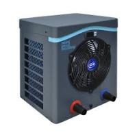
Thank you for using GRE swimming pool heat pump for your pool heating, it will heat your pool water and keep the constant temperature when the air ambient temperature is between 7 and 43ircC

ATTENTION: This manual includes all the necessary information with the use and the installation of your heat pump.
The installer must read the manual and attentively follow the instructions in implementation and maintenance. Please keep on pass on this manual for later throughout the appliance 's service life.
The installer is responsible for the installation of the product and should follow all the instructions of the manufacturer and the regulations in application. Incorrect installation against the manual implies the exclusion of the entire guarantee.
The manufacturer declines any responsibility for the damage caused with the people, objects and of the errors due to the installation that disobey the manual guideline. Any use that is without conformity at the origin of its manufacturing will be regarded as dangerous.
1. Specifications
1.1 Technical data GRE heat pumps
| Model | | HPG25 | HPG40 | HPG50 | HPG70 |
| Code | | 74158 | 74159 | 74160 | 74161 |
| * Performance at Air 28 °C,Water 28 °C,Humidity 80% |
| Heating capacity | Kw | 5 | 7.5 | 11 | 14 |
| Power consumption | Kw | 1.00 | 1.40 | 2.20 | 2.60 |
| C.O.P. | | 5 | 5.4 | 5 | 5.4 |
| * Performance at Air 15 °C,Water 26 °C,Humidity 70% |
| Heating capacity | Kw | 3.5 | 5.5 | 7.5 | 9.5 |
| Power consumption | Kw | 0.88 | 1.25 | 1.75 | 2.25 |
| C.O.P. | | 4 | 4.4 | 4.3 | 4.2 |
| * General Info |
| Compressor type | | Rotary |
| Voltage | V | 220-240V/50Hz/1PH |
| Rated current | A | 4.4 | 6.2 | 9.8 | 11.5 |
| Minimum fuse | A | 12 | 17 | 27 | 32 |
| Maximum pool volume** | m3 | < 25 | < 45 | < 60 | < 75 |
| Advised water flux | m3/h | 2.5~3.2 | 2.5~4.2 | 3.5~7.1 | 4-7.9 |
| Water pressure drop | Kpa | 12 | 12 | 15 | 15 |
| Heat exchanger | | Twist-Titanium tube in PVC |
| Water connection | Mm | 50 |
| Fan quantity | | 1 |
| Ventilation type | | Horizontal |
| Fan speed | RPM | 830~870 | 650 |
| Power input of Fan | W | 59 | 59 | 86 | 120 |
| Protection rating | | IPX4 |
| Max Pressure-suction and discharge side | MPa | 4.2MPa |
| Noise level(10m) | dB(A) | 32 | 33 | 37 | 37 |
| Noise level(1m) | dB(A) | 50 | 51 | 54 | 54 |
| Refrigerant | | R32 |
| Refrigerant quantity | g | 400 | 450 | 800 | 900 |
| CO2 equivalent | Tonne | 0.27 | 0.30 | 0.54 | 0.61 |
| Net weight | Kg | 36 | 46 | 65 | 77 |
| Gross weight | Kg | 38 | 48 | 72 | 81 |
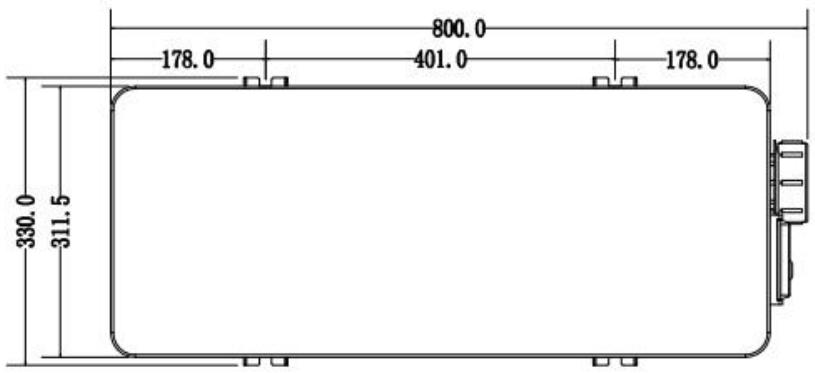
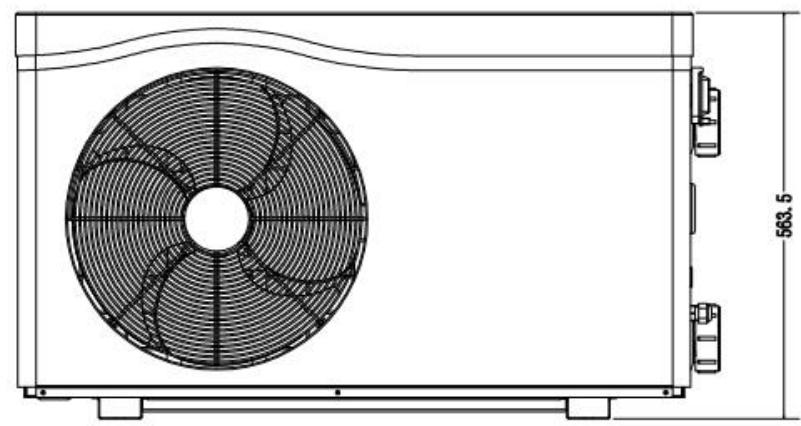
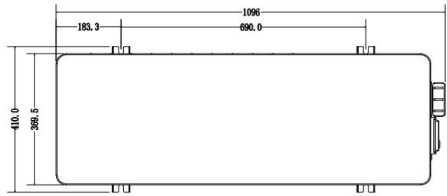
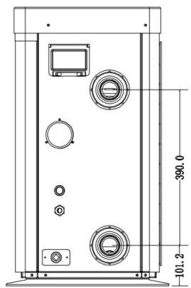
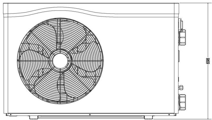
| Net dimension | mm | 800*330*515.5 | 977.5*386*563.5 | 1096*410*689 |
| Packing dimension | mm | 830*395*555 | 1000*430*600 | 1120*465*725 |
- Above data are subjects to modification without notice.
**Check our packaging or website for more details.
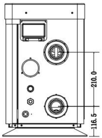
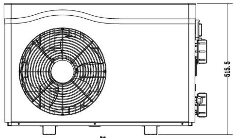
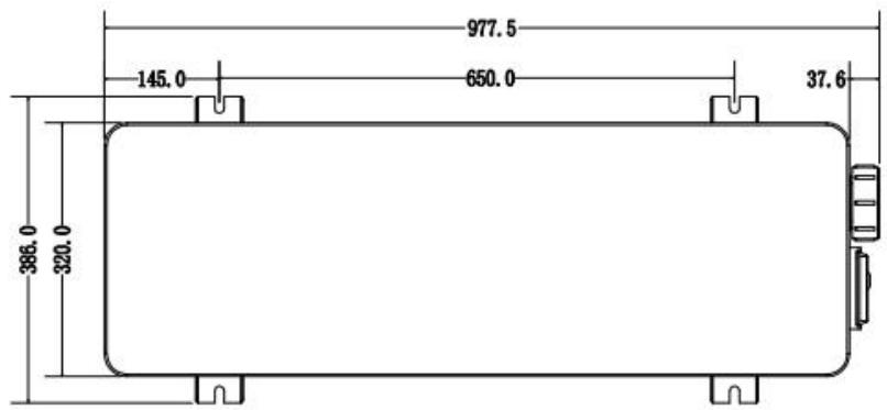
2. Dimension
unit:mm
Model:HPG25
Model:HPG40 & HPG50
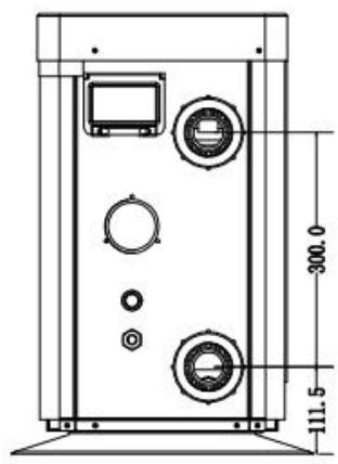
Model:HPG70
3. Installation and connection
3.1 Notes
The factory supplies only the heat pump. All other components, including a bypass if necessary, must be provided by the user or the installer.
Attention:
Please observe the following rules when installing the heat pump:
- Any addition of chemicals must take place in the piping located downstream from the heat pump.
- Install a bypass if the water flow from the swimming pool pump is more than 20% greater than the allowable flow through the heat exchanger of the heat pump.
- Install the heat pump above the water level of the swimming pool.
- Always place the heat pump on a solid foundation and use the included rubber mounts to avoid vibration and noise.
- Always hold the heat pump upright. If the unit has been held at an angle, wait at least 24 hours before starting the heat pump.
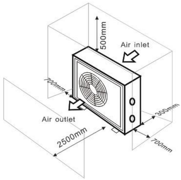
3.2 Heat pump location
The unit will work properly in any desired location as long as the following three items are present:
1. Fresh air - 2. Electricity - 3. Swimming pool filters
The unit may be installed in virtually any outdoor location as long as the specified minimum distances to other objects are maintained (see drawing below). Please consult your installer for installation with an indoor pool. Installation in a windy location does not present any problem at all, unlike the situation with a gas heater (including pilot flame problems).
ATTENTION: Never install the unit in a closed room with a limited air volume in which the air expelled from the unit will be reused, or close to shrubbery that could block the air inlet. Such locations impair the continuous supply of fresh air, resulting in reduced efficiency and possibly preventing sufficient heat output. See the drawing below for minimum dimensions.
The heat pump is normally installed within a perimeter area extending 7.5m from the swimming pool. The greater the distance from the pool, the greater the heat loss in the pipes. As the pipes are mostly underground, the heat loss is low for distances up to 30m (15 m from and to the pump; 30 m in total) unless the ground is wet or the groundwater level is high. A rough estimate of the heat loss per 30m is 0.6 kWh (2,000 BTU) for every 5ircC difference between the water temperature in the pool and the temperature of the soil surrounding the pipe. This increases the operating time by 3% to 5% .
3.3 Distance from your swimming pool
3.4 Check-valve installation
Note: If automatic dosing equipment for chlorine and acidity (pH) is used, it is essential to protect the heat pump against excessively high chemical concentrations which may corrode the heat exchanger. For this reason, equipment of this sort must always be fitted in the piping on the downstream side of the heat pump, and it is recommended to install a check-valve to prevent reverse flow in the absence of water circulation. Damage to the heat pump caused by failure to observe this instruction is not covered by the warranty.
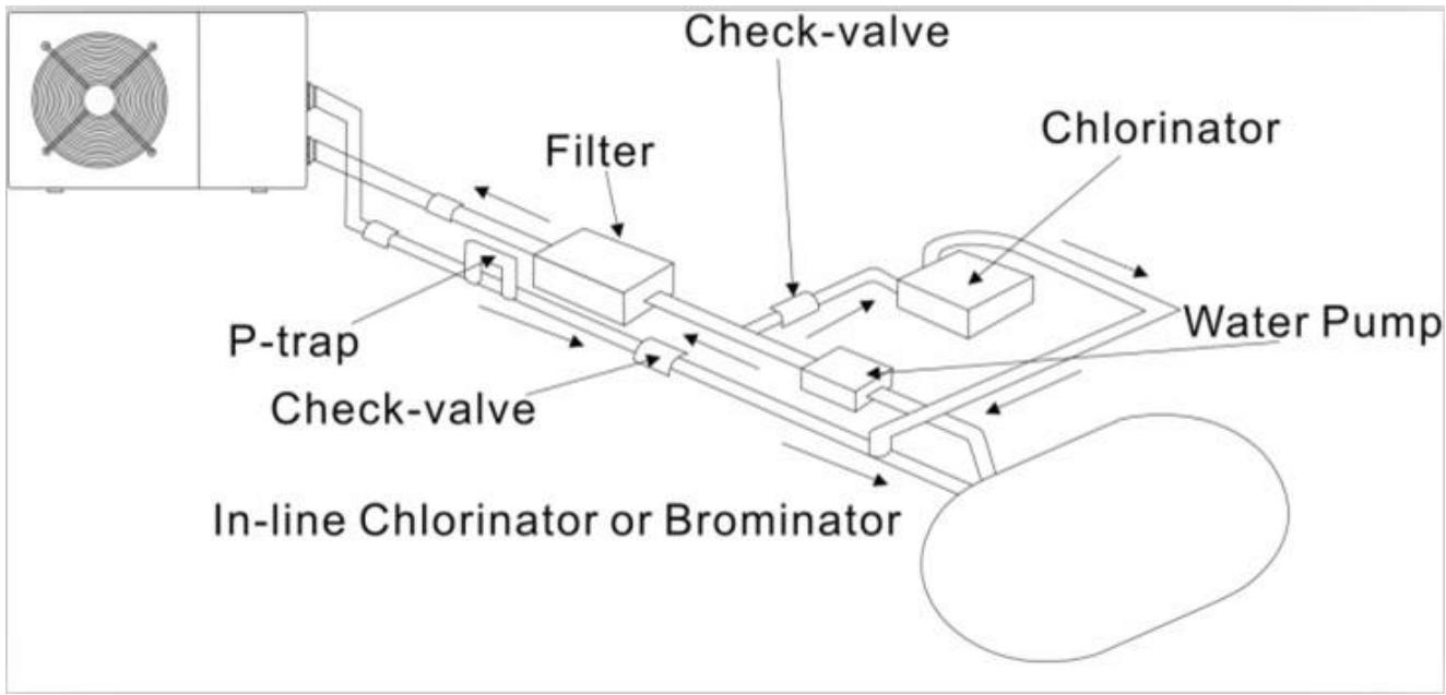
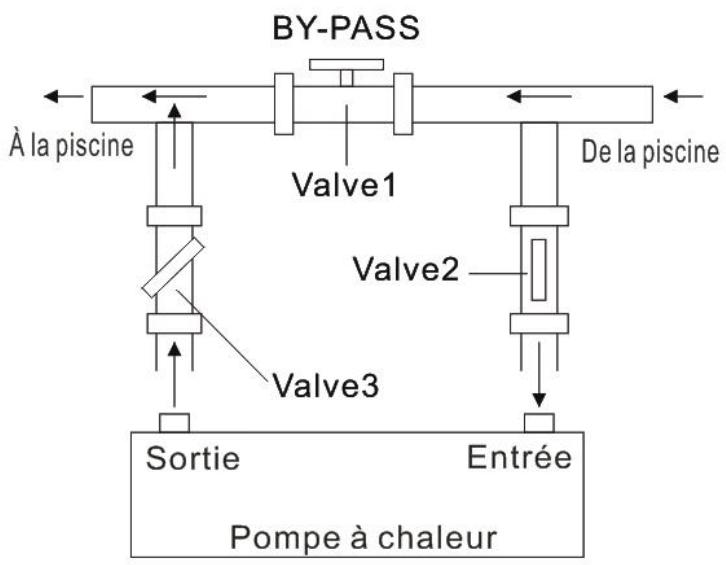
3.5 Typical arrangement
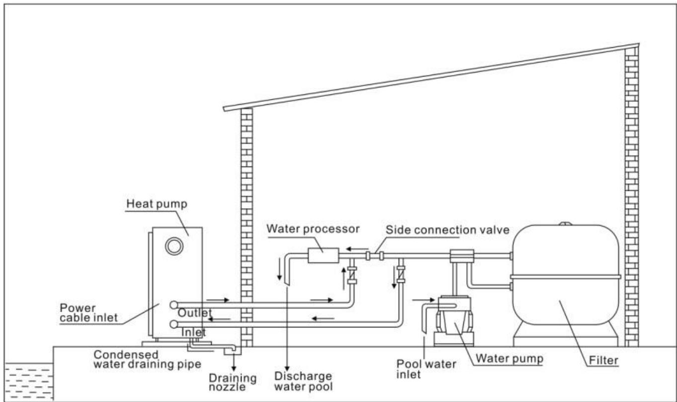
Note: This arrangement is only an illustrative example.
3.6 Adjusting the bypass
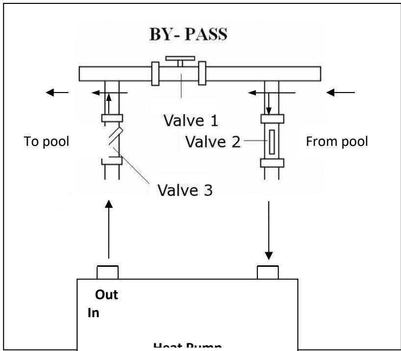
Please take below steps to adjust the by-pass:
- Valve 1 wide open. Valve 2 & valve 3 closed.
- Slowly open valve 2 & valve 3 by half, then close the valve 1 slowly to increase the water flow to valve 2 & valve 3.
- If it shows 'ON' or 'EE3' on display, it means the water flow into heat pump is not enough, then you need adjust the valves to increase the water flow through the heat pump.
How to get the optimum water flow.
Please turn on the heat pump under heating function, firstly close the by-pass then open it slowly to start the heat pump (the machine can't start running when the water flow is insufficient)
Continue to adjust the by-pass, at the meantime to check the Inlet water temp. & Outlet water temp., it will be optimum when the difference is around 2 degree.
3.7 Electrical connection
Note: Although the heat pump is electrically isolated from the rest of the swimming pool system, this only prevents the flow of electrical current to or from the water in the pool. Earthing is still required for protection against short-circuits inside the unit. Always provide a good earth connection. The installer must consult the electricity provider if necessary and ensure that the equipment is connected correctly to an electricity network with impedance under 0.095 ohm.
Warning : Before any work inside the appliance, you must cut the appliance’s electricity supply as there is a risk of electric shock which may cause material damage, serious injury or even death.
- Incorrectly tightened terminals may cause the terminal box to heat up, which can invalidate the warranty.
- Only a qualified and experienced technician is authorised to carry out cabling work within the appliance or to replace the power cord.
Before connecting the unit, verify that the supply voltage matches the operating voltage of the heat pump. It is recommended to connect the heat pump to a circuit with its own fuse or circuit breaker (slow type; curve D) and to use adequate wiring.
Connect the electrical wires to the terminal block marked ‘ POWER SUPPLY’.
A second terminal block marked 'WATER PUMP' is located next to the first one. The filter pump (max. 5 A 0V ) can be connected to the second terminal block here. This allows the filter pump operation to be controlled by the heat pump.
3.8 Initial operation
Note: In order to heat the water in the pool (or hot tub), the filter pump must be running to cause the water to circulate through the heat pump. The heat pump will not start up if the water is not circulating.
After all connections have been made and checked, carry out the following procedure:
- Switch on the filter pump. Check for leaks and verify that water is flowing from and to the swimming pool.
- Connect power to the heat pump and press the On/Off button on the electronic control panel. The unit will start up after the time delay expires (see below).
- After a few minutes, check whether the air blowing out of the unit is cooler.
- When turn off the filter pump, the unit should also turn off automatically, if not, then adjust the flow switch.
- Allow the heat pump and the filter pump to run 24 hours a day until the desired water temperature is reached. The heat pump will stop running at this point. After this, it will restart automatically (as long as the filter pump is running) whenever the swimming pool water temperature drops 2 degree below the set temperature.
Depending on the initial temperature of the water in the swimming pool and the air temperature, it may take several days to heat the water to the desired temperature. A good swimming pool cover can dramatically reduce the required length of time.
Water Flow Switch:
It is equipped with a flow switch for protecting the HP unit running with adequate water flow rate .It will turn on when the pool pump runs and shut it off when the pump shuts off. If the pool water level higher than 1 m above or below the heat pump's automatic adjustment knob, your dealer may need to adjust its initial start up.
Time delay - The heat pump has a built-in 3-minute start-up delay to protect the circuitry and avoid excessive contact wear. The unit will restart automatically after this time delay expires. Even a brief power interruption will trigger this time delay and prevent the unit from restarting immediately. Additional power interruptions during this delay period do not affect the 3-minute duration of the delay.
3.9 Condensation
The air drawn into the heat pump is strongly cooled by the operation of the heat pump for heating the pool water, which may cause condensation on the fins of the evaporator. The amount of condensation may be as much as several litres per hour at high relative humidity. This is sometimes mistakenly regarded as a water leak.
4. Accessories
4.1 Accessories list
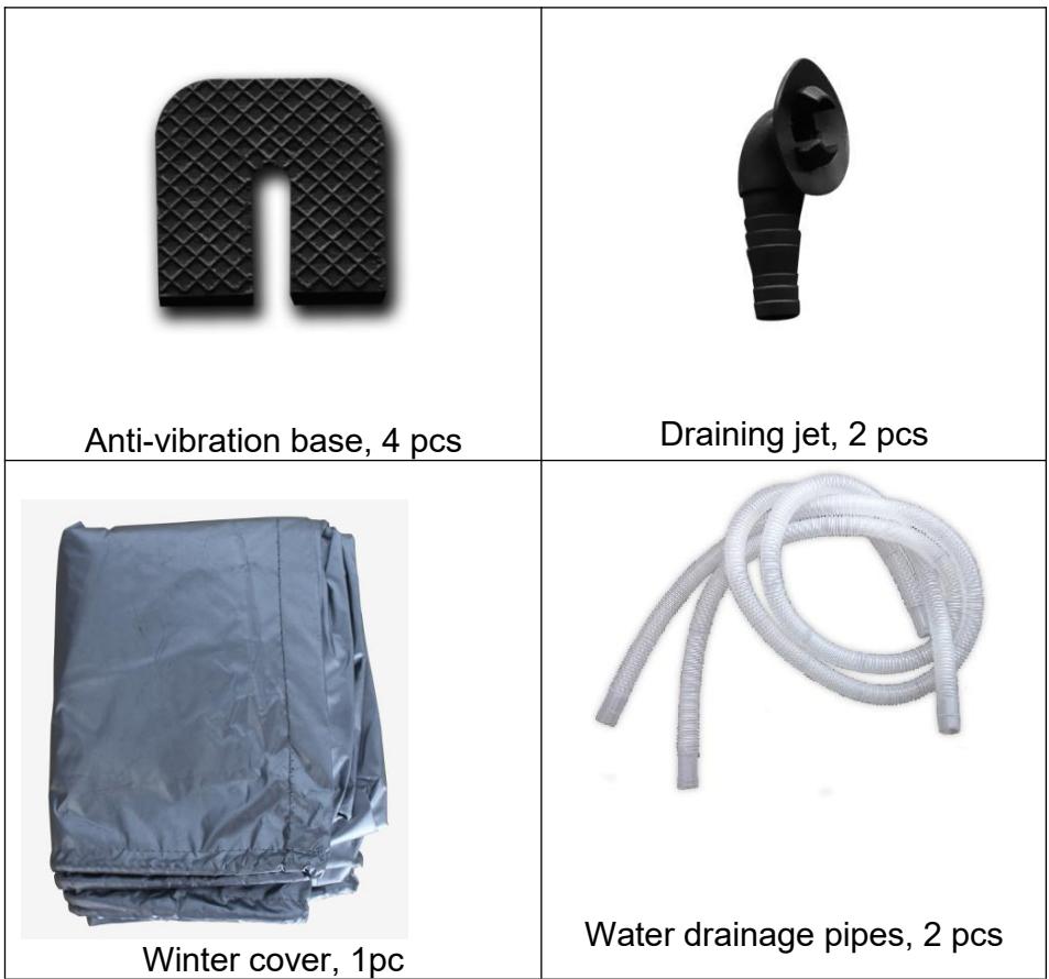
4.2 Accessories Installation
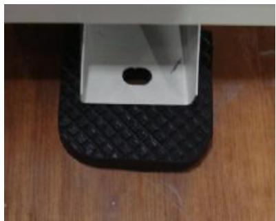
Anti-vibration bases
- Take out 4 Anti-vibration bases
- Put them one by one on the bottom of machine like the picture.
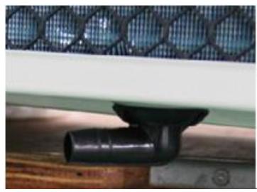
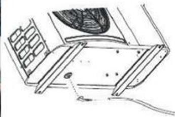
Draining jet
- Install the draining jet under the bottom panel
- Connect with a water pipe to drain out the water.
Note: Lift the heat pump to install the jet. Never overturn the heat pump, it could damage the compressor.
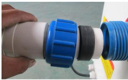
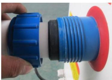
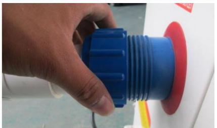
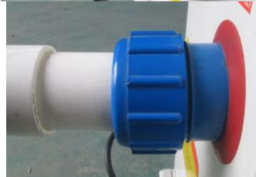
Water Inlet & outlet junction
- Install the two joints like the picture shows
- Screw them onto the water Inlet
& outlet junction
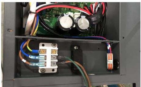
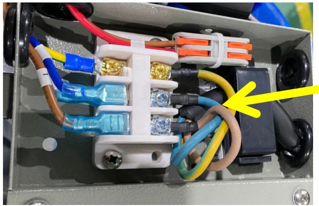
Cable wiring
- Open the cover of the electric box
- Fix the power supply wire on joints L N E
- Open the cover of the electric box
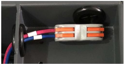
- With the connector 1 and 2 you can pilot the water filtration through the timer of the filtration (dry contact)
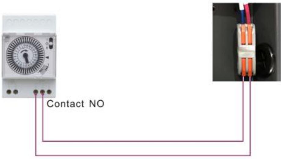
Dry contact timer connection Timer
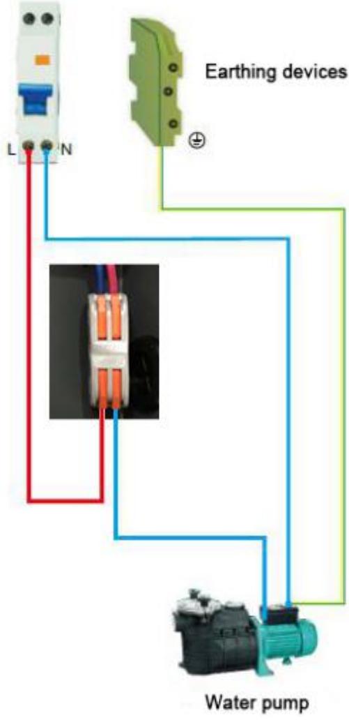
Dry contact pump connection
Leakage protector
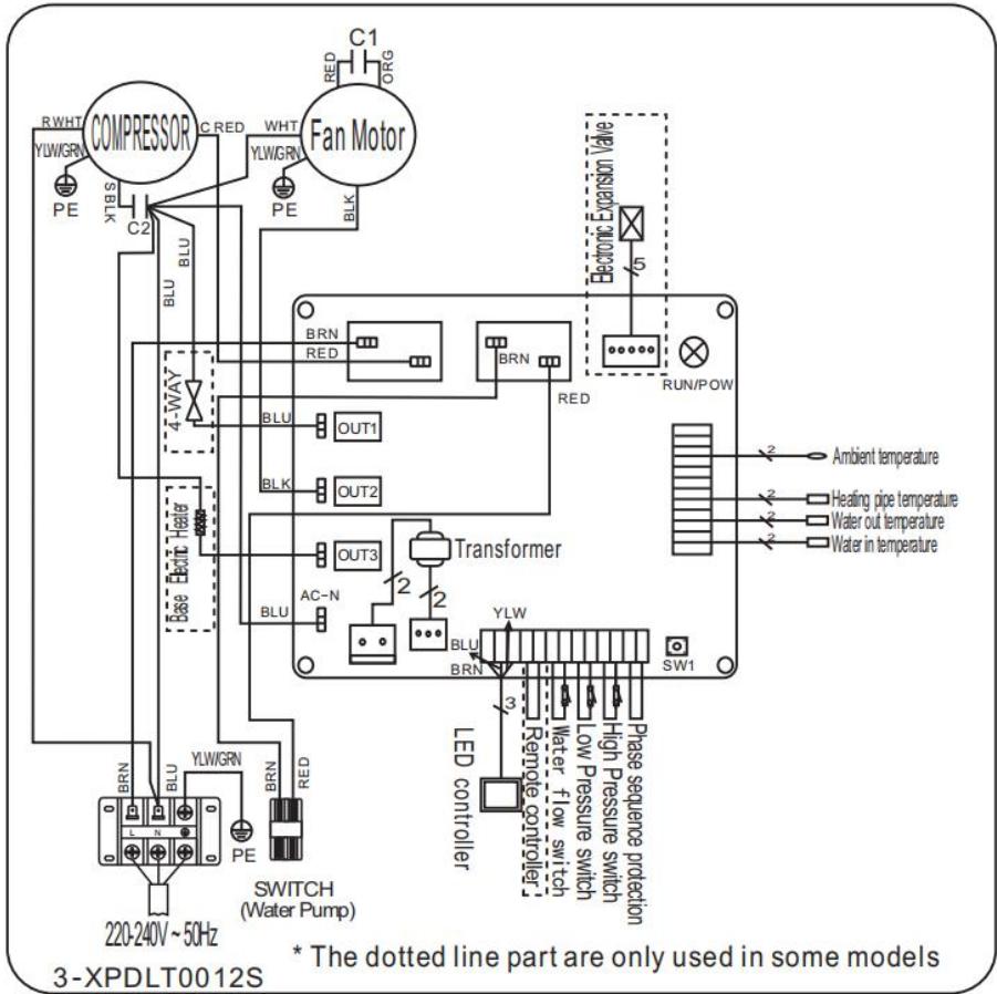
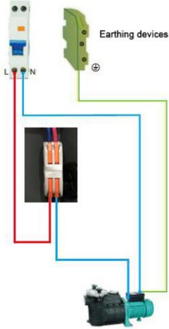
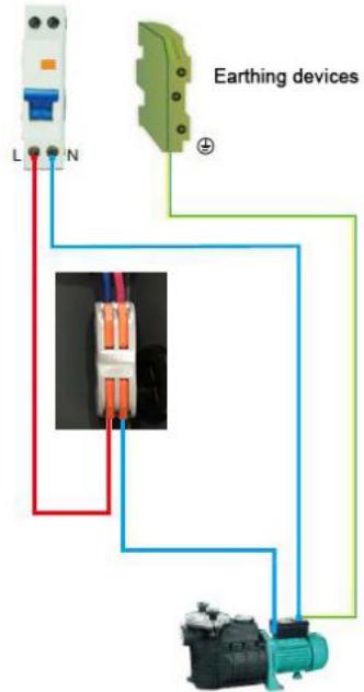
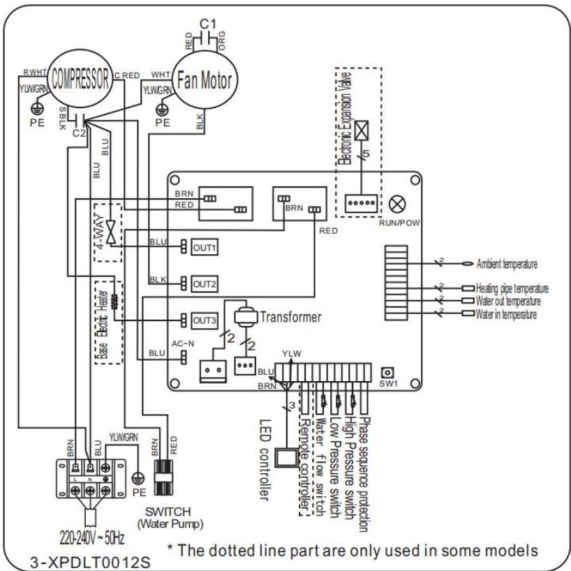
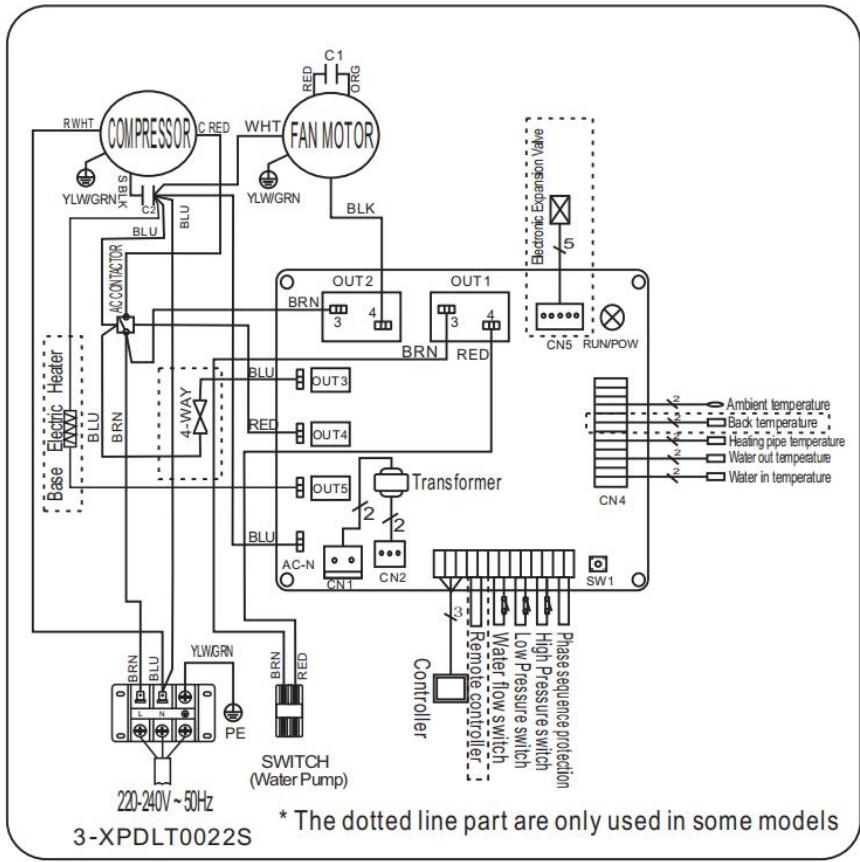
5. Electrical Wiring
5.1 SWIMMING POOL HEAT PUMP WIRING DIAGRAM
HPG25/HPG40
HPG50/HPG70
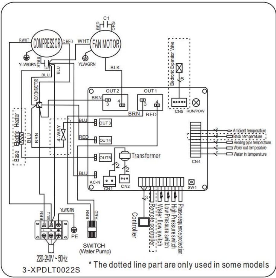
NOTE:
(1)Above electrical wiring diagram only for your reference, it is subjected to the wiring diagram posted on the machine.
(2) The swimming pool heat pump must be connected ground wire well, although the unit heat exchanger is electrically isolated from the rest of the unit. Grounding the unit is still required to protect you against short circuits inside the unit. Bonding is also required.
Disconnect: A disconnect means (circuit breaker, fused or un-fused switch) should be located within sight of and readily accessible from the unit. This is common practice on commercial and residential heat pumps. It prevents remotely-energizing unattended equipment and permits turning off power at the unit while the unit is being serviced.
6. Operation
(1) Guide for operation
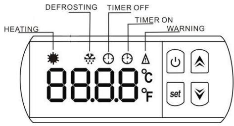
(2) Start the pool heat pump
Press to start the heat pump, the LED display will show the inlet water temperature and current working mode after 5s.
(3) Stop the pool heat pump
Press once again to stop the heat pump, the LED display shows 'OFF'
(4) Water temperature setting
Press or to set the desired water in temperature in current working mode, then Press to save setting and exit.
(5) TIME setting
Press set button, then press to enter into "TIME display;
** HOUR SETTING**
Press set again to "HOUR" setting, "HH" flashed, then press or to adjust the HOUR from 0 to 23;
MINUTE SETTING
Press set to enter into MINUTE setting, "MM" flashed, then press or to adjust the MINUTE from 0 to 59.
(6) TIMER ON Setting
Press set button, then press Y button twice to enter into TIMER ON setting. When you see the starting time display on controller, Press set to confirm to enter into TIMER ON setting interface, finally press A or Y to adjust the starting time.
(7) TIMER OFF Setting
Press set button, then press Y button 3 times to enter into "TIME OFF" setting. When you see the stopping time display on controller, Press set to confirm to enter into TIMER OFF setting interface, finally press A or Y to adjust the stopping time.
**Above operations, you could press button to save the setting and quick-exit the program. **
(8) How to check the parameters?
Press set button,then press to check the parameter of B-C-D-E-F-G.
| Code | Parameter | Range |
| B | Water in temperature | -9 to 99°C |
| C | Water out Temperature | -9 to 99°C |
| D | Heating pipe temperature | -29 to 99°C |
| E | Gas return temperature | -29 to 99°C |
| F | Ambient temperature | -29 to 99°C |
| H | Actual steps of Electronic expansion valve | N*5 |
**ATTENTION**
When you press set and press A button to enter into parameter checking, the Y button could not be operated. At the same as above, when you press set and press Y button to check TIME - starting time of TIMER and Stopping time of TIMER, the A could be not operated.
(9) Parameter setting
This part should be operated only by qualified technicians for after-service or maintenance.
(1) Press set + at same time in 5 second, display flashes,
(2) Press A or to choose the parameter you want to adjust
(3) Press set again to enter into interface
(4) Press or to adjust the value setting.
(5) Finally press set once again to save the data or press to save and quick-exit the parameter setting.
| Parameter | Meaning | Range | Default | Remarks |
| 1 | To set the entering water temp. under heating mode | 15-42°C | 28°C | Adjustable |
| 2 | Entry into defrosting time period | 30-90MIN | 40MIN | Adjustable |
| 3 | Terms of Entry defrosting function | -30°C to0°C | -7°C | Adjustable |
| 4 | Terms of Exit defrosting | 2 to 30°C | 20°C | Adjustable |
| 5 | Time of Exit defrosting | 1 to 12MIN | 12MIN | Adjustable |
| 6 | Mode: 0 Heat | 0 | 0 | Not adjustable |
| 7 | Mode selection of Electronic expansion valve | 0-1 | 1(auto) | Adjustable |
| A | Manual adjustment steps of electronic expansion valve | 18-94 | 70 | Adjustable |
| L | Entering water temperature calibration | -9.9-9.9 | 0 | Adjustable |
Recover to Factory default setting
Long press and set simultaneously in 10 second to recover to factory default setting, it will display "0000" and then back to "OFF".
7. Troubleshooting
7.1 Error code display on LED wire controller
| Malfunction | Error code | Reason | Solution |
| Low ambient temperature protection | PP0 | Ambient temperature is too low | |
| Inlet water temperature sensor failure | PP1 | The sensor in open or short circuit | Check or change the sensor |
| Outlet water temperature sensor failure | PP2 | The sensor in open or short circuit | Check or change the sensor |
| Heating condenser sensor failure | PP3 | The sensor in open or short circuit | Check or change the sensor |
| Gas return sensor failure | PP4 | The sensor in open or short circuit | Check or change the sensor |
| Ambient temperature sensor failure | PP5 | The sensor in open or short circuit | Check or change the sensor |
| Temperature difference too much protection water inlet and outlet | PP6 | Water flow volume is not enough | Check the water flow volume or water jammed or not. |
| First grade antifreeze protection in Winter | PP7 | Ambient temperature or water inlet temperature is too low | Water pump will run automatically for first grade antifreeze |
| Second grade antifreeze protection in Winter | PP7 | Ambient temperature or water inlet temperature is too low | Heat pump will start heating for second grade antifreeze |
| High pressure protection | EE1 | 1. Refrigerant is too much
2. Air flow is not enough | 1. Discharge redundant refrigerant from HP gas system
2. Clean the air exchanger |
| Low pressure protection | EE2 | 1. Refrigerant is not enough
2. Water flow is not enough
3. Filter jammed or capillary jammed | 1. Check if there is any gas leakage, re-fill the refrigerant
2. Clean the air exchanger
3. Replace the filter or capillary |
| Flow switch closed | ON /EE3 | Low water flow, wrong flow direction, or flow switch failure. | Check if the water flow is enough and flow in right direction, or else the flow switch could be failed. |
| Inlet and outlet water temperature difference malfunction | EE5 | Water flow volume is not enough, water pressure difference is too low | Check the water flow rate or water system is jammed or not |
| Communication failure | EE8 | Wire connection is not good | Check the wire connection |
7.2 Malfunction display on PCB
| Protection /Malfunction | Controller display | Malfunction light display on PCB |
| Heat pump standby status | ON | ● |
| Heat pump running | Water in temperature | ● |
| Low ambient temperature protection | PP0 | ● |
| Inlet water temperature sensor failure | PP1 | ● |
| Outlet water temperature sensor failure | PP2 | ● |
| Heating condenser sensor failure | PP3 | ● |
| Gas return sensor failure | PP4 | ● |
| Ambient temperature sensor failure | PP5 | ● |
| Temperature difference too much protection between water inlet and outlet | PP6 | ● |
| First grade antifreeze protection in Winter | PP7 | ● |
| Second grade antifreeze protection in Winter | PP7 | ● |
| High pressure protection | EE1 | ● |
| Low pressure protection | EE2 | ● |
| Flow switch closed | ON/EE3 | ● |
| Inlet and outlet water temperature difference malfunction | EE5 | ● |
| Defrosting | Defrosting | …… |
7.3 Other Malfunctions and Solutions (No display on LED wire controller)
| Malfunctions | Observing | Reasons | Solution |
| Heat pump is not running | LED wire controller no display. | No power supply | Check cable and circuit breaker if it is connected |
| LED wire controller displays the actual time. | Heat pump under standby status | Startup heat pump to run. |
| LED wire controller displays the actual water temperature. | 1. Water temperature is reaching to setting value, HP under constant temperature status.
2. Heat pump just starts to run.
3. Under defrosting. | 1. Verify water temperature setting.
2. Startup heat pump after a few minutes.
3. LED wire controller should display "Defrosting". |
| Short running | LED displays actual water temperature, no error code displays. | 1. Fan NO running.
2. Air ventilation is not enough.
3. Refrigerant is not enough. | 1. Check the cable connections between the motor and fan, if necessary, it should be replaced.
2. Check the location of heat pump unit, and eliminate all obstacles to make good air ventilation.
3. Replace or repair the heat pump unit. |
| Water stains | Water stains on heat pump unit. | 1. Concreting.
2. Water leakage. | 1. No action.
2. Check the titanium heat exchanger carefully if it is any defect. |
| Too much ice on evaporator | Too much ice on evaporator. | | 1. Check the location of heat pump unit, and eliminate all obstacles to make good air ventilation.
2. Replace or repair the heat pump unit. |
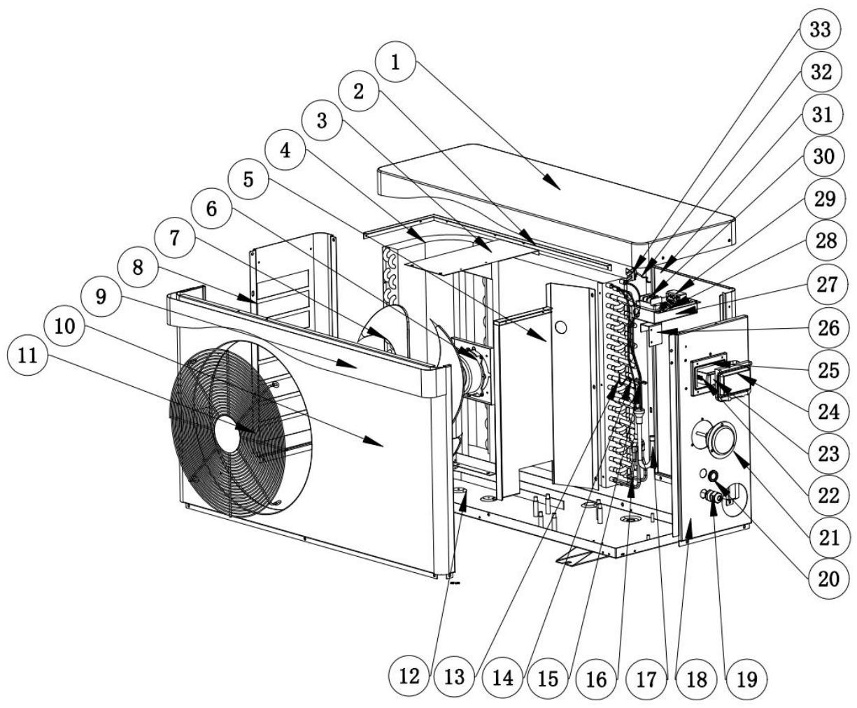
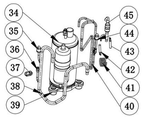
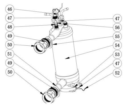
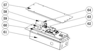
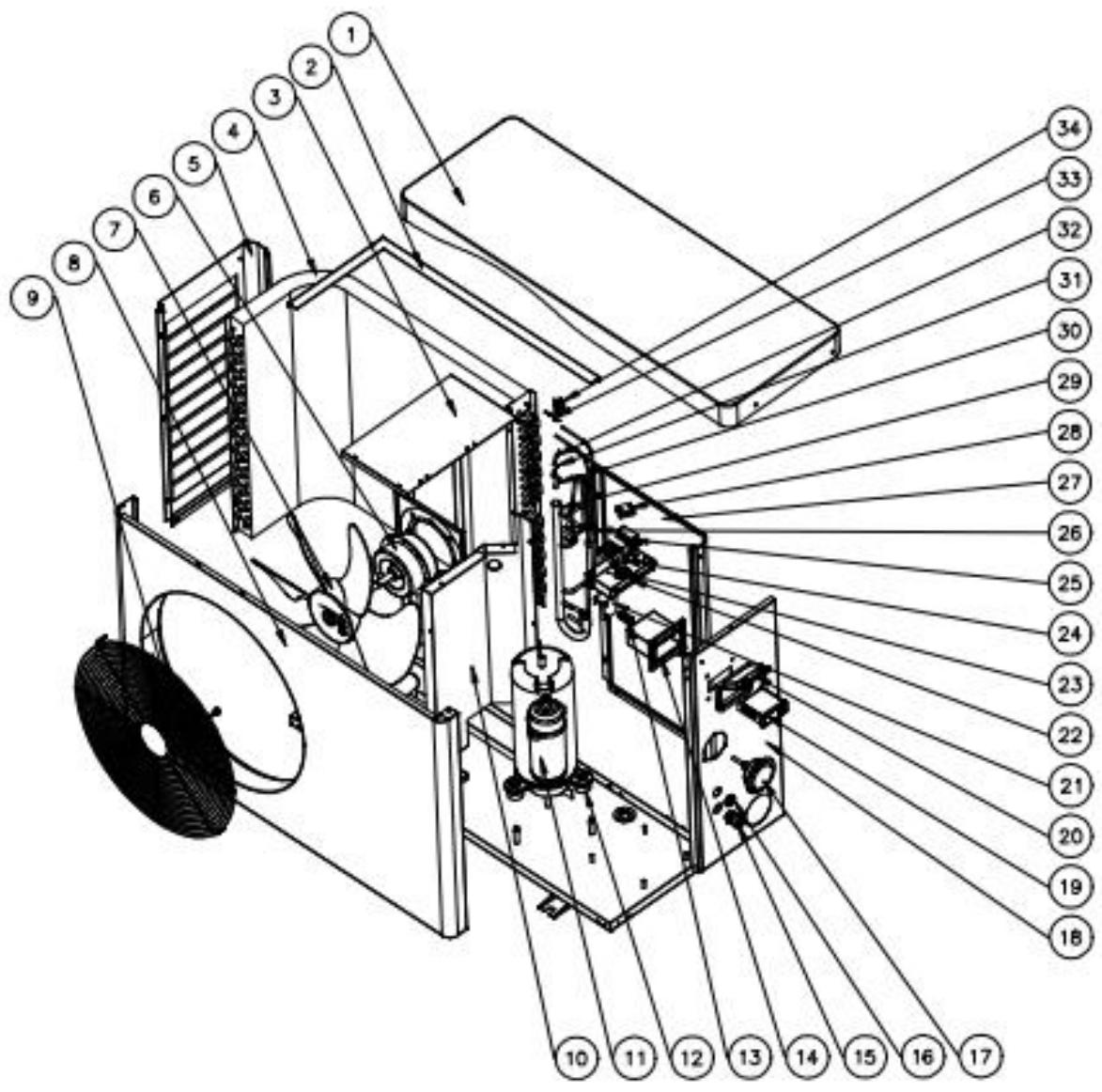
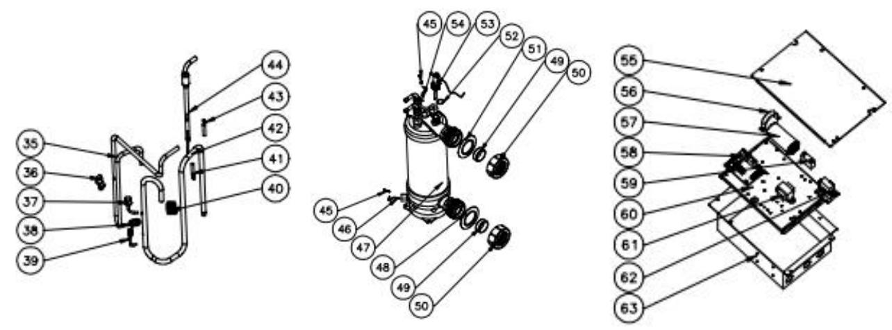
8. Exploded Diagram
Model: HPG25
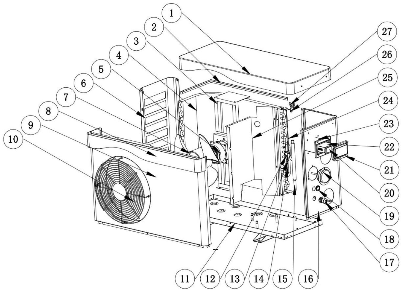
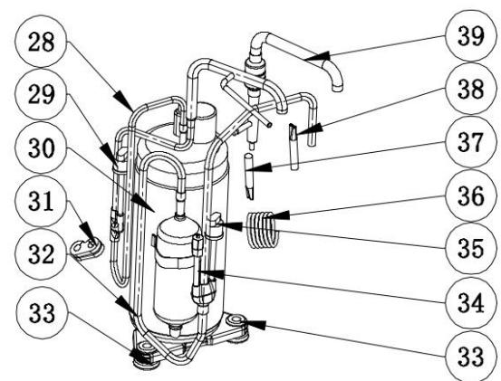
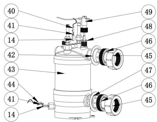
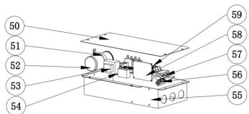
| No. | Part Name | No. | Part Name |
| 1 | Top cover | 31 | Rubber fixing block |
| 2 | Bracket panel | 32 | Gas return piping |
| 3 | Fan motor bracket | 33 | Compressor damping feet |
| 4 | Evaporator | 34 | Gas valve |
| 5 | Fan motor | 35 | Low pressure switch |
| 6 | Left Panel | 36 | Capillary |
| 7 | Fan blade | 37 | Transition pipe |
| 8 | Blue Strip | 38 | Gauge pipe |
| 9 | Front panel | 39 | Pipe(Exchanger to capillary) |
| 10 | Ventilation grill | 40 | Water outlet temp. sensor |
| 11 | Base tray | 41 | Exchanger temperature sensor clip |
| 12 | Evaporator temperature sensor | 42 | Red rubber ring |
| 13 | Sensor holder | 43 | Titanium heat exchanger |
| 14 | Clip | 44 | Water inlet temp. sensor |
| 15 | Evaporator pipe | 45 | Water connection sets |
| 16 | Side panel | 46 | Water connection sets |
| 17 | Cable connector | 47 | Blue rubber ring |
| 18 | Rubber plug | 48 | Sealing ring |
| 19 | Pressure gauge | 49 | Water flow switch |
| 20 | Controller | 50 | Electric box cover |
| 21 | Controller box | 51 | Capacitor clip |
| 22 | Controller cover | 52 | Compressor capacitance |
| 23 | Controller box cover | 53 | Transformer |
| 24 | Distribution pipe | 54 | Fan motor capacitance |
| 25 | Isolation panel | 55 | Electric box |
| 26 | Ambient temp. sensor | 56 | Two position terminal |
| 27 | Ambient temp. sensor clip | 57 | Clip |
| 28 | Discharge pipe | 58 | PCB |
| 29 | High pressure switch | 59 | Three position terminal |
| 30 | Compressor | | |
| No. | Part Name | No. | Part Name |
| 1 | Top cover | 33 | Ambient temp. sensor clip |
| 2 | Bracket panel | 34 | Compressor |
| 3 | Fan motor bracket | 35 | Low pressure switch |
| 4 | Evaporator | 36 | Gas valve |
| 5 | Isolation panel | 37 | Rubber fixing block |
| 6 | Fan motor | 38 | Gas return piping |
| 7 | Fan blade | 39 | Compressor damping feet |
| 8 | Left Panel | 40 | Discharge pipe |
| 9 | Blue Strip | 41 | Capillary |
| 10 | Front panel | 42 | Transition pipe |
| 11 | Ventilation grill | 43 | Pipe |
| 12 | Base tray | 44 | High pressure switch |
| 13 | Evaporator temperature sensor | 45 | Pipe(Exchanger to capillary) |
| 14 | Clip | 46 | Water outlet temp. sensor |
| 15 | Sensor holder | 47 | Sensor clip |
| 16 | Evaporator pipe | 48 | O'ring |
| 17 | Distribution pipe | 49 | Water connection sets |
| 18 | Side panel | 50 | Water connection sets |
| 19 | Cable connector | 51 | Blue rubber ring |
| 20 | Rubber plug | 52 | Water inlet temp. sensor |
| 21 | Pressure gauge | 53 | Clip |
| 22 | Controller cover | 54 | Titanium heat exchanger |
| 23 | Controller | 55 | Red rubber ring |
| 24 | Controller box | 56 | Water flow switch |
| 25 | Controller box cover | 57 | Electric box cover |
| 26 | Support plate | 58 | Compressor capacitance |
| 27 | Wiring box | 59 | Transformer |
| 28 | Two position terminal | 60 | Scale panel |
| 29 | Clip | 61 | Electric box |
| 30 | Three position terminal | 62 | PCB |
| 31 | Back panel | 63 | Fan motor capacitance |
| 32 | Ambient temp. sensor | 64 | Capacitor clip |
| No. | Part Name | No. | Part Name |
| 1 | Top cover | 33 | Ambient temperature sensor |
| 2 | Support plate | 34 | Sensor clip |
| 3 | Motor bracket | 35 | Exhaust pipe |
| 4 | Evaporator | 36 | High pressure switch |
| 5 | Left Panel | 37 | Low pressure switch |
| 6 | Fan motor | 38 | Fixing block |
| 7 | Fan blade | 39 | Needle valve |
| 8 | Front ventilation panel | 40 | Capillary |
| 9 | Ventilation grill | 41 | Transition pipe |
| 10 | Isolation Panel | 42 | Gas return pipe |
| 11 | Compressor | 43 | Pressure pipe |
| 12 | Rubber feet of compressor | 44 | Titanium exchanger to capillary |
| 13 | Cable connector | 45 | Sensor Clip |
| 14 | Controller box | 46 | Water inlet temperature sensor |
| 15 | Cable connector | 47 | Titanium heat exchanger |
| 16 | Rubber ring | 48 | Blue Rubber ring |
| 17 | Pressure gauge | 49 | O'ring |
| 18 | Side panel | 50 | Water connection |
| 19 | Controller | 51 | Red Rubber ring |
| 20 | Waterproof box | 52 | Sealing ring for flow switch |
| 21 | Support plate | 53 | Water flow switch |
| 22 | Wiring box | 54 | Water outlet temperature sensor |
| 23 | Two position terminal | 55 | Electric box cover |
| 24 | Three position terminal | 56 | Capacitor clamp |
| 25 | Clamp | 57 | Compressor capacitance |
| 26 | Distributor pipe | 58 | PCB |
| 27 | Back panel | 59 | Fan capacitance |
| 28 | Rubber fixing block | 60 | Scale panel |
| 29 | Collecting Pipe | 61 | Transformer |
| 30 | Sensor casing pipe | 62 | AC contactor |
| 31 | Spring blade of sensor pipe | 63 | Electric box |
| 32 | Coil pipe Temp sensor | | |
9. Maintenance
Warning!
- Before any maintenance work on the appliance, you must cut the electricity supply as there is a risk of electric shock which may cause material damage,serious injury or even death.
- It is recommended that the appliance undergo general servicing at least on a yearly basis to ensure its proper operation, maintain performance levels and prevent any possible failures. These operations are carried out at the user's expense, by a qualified technician. for maintenance to be carried out by a qualified technician.
- for maintenance to be carried out by a qualified technician, please read the safety instructions in the previous pages provided in the chapter entitled "maintenance: warnings concerning appliances containing R32 refrigerant" before performing any of the maintenance operations described below.
(1) You should check the water supply system regularly to avoid the air entering the system and occurrence of low water flow, because it would reduce the performance and reliability of HP unit.
(2) Clean your pools and filtration system regularly to avoid the damage of the unit as a result of the dirty of clogged filter.
(3) In another way, you should check the unit is water fully before the unit starts to run again.
(4)After the unit is conditioned for the winter season, it's recommended to cover the heat pump with special winter cover.
(5) When the unit is running, there is all the time a little water discharge under the unit.
(6) R32 pressure and temperature mapping table
| Condition | Power OFF |
| Ambient Temperature | -5-5 °C | 5-15 °C | 15-25 °C | 25-35°C |
| Water temperature | / | / | / | / |
| Pressure gauge reading | 0.68-0.93 MPa | 0.93-1.25 MPa | 1.25-1.64 MPa | 1.64-2.1 MPa |
| Condition | Running (Heating) |
| Ambient Temperature | / | / | / | / | / |
| Water temperature | 10-15°C | 15-20°C | 20-25°C | 25-30°C | 30-35 °C |
| Pressure gauge reading | 1.3-1.8 MPa | 1.5-1.9 MPa | 1.6-2.3 MPa | 1.9-2.8 MPa | 2.1-3.5 MPa |
(7) Please always empty the water in heat pump during winter time or when the ambient temperature drops below 0ircC , or else the Titanium exchanger will be damaged because of being frozen, in such case, your warranty will be lost.
ADVERTECIAS
Leakage protector
Water pump
Leakage protector
Water pump
5. Cavi Elettrici
5.1 PISCINA POMPDA CALORE SCHEMA
HPG25/HPG40
HPG50/HPG70
NOTE:
ALGEMENE WAARSCHUWINGEN
WAARSCHUWINGEN MET BETREKKING TOT ELEKTRISCHE APPARATEN
3.6 Installing van bypass
Wartosć这段时间 probably don't have any kind of a good idea.
1.1 In accordance with these provisions, the seller guarantees that the product corresponding to this guarantee ("the Product") is in perfect condition at the time of delivery.
1.2 The Guarantee Term for the Product is two (2) years from the time it is delivered to the purchaser.
1.3 In the event of any defect in the Product that is notified by the purchaser to the seller during the Guarantee Term, the seller will be obliged to repair or replace the Product, at his own cost and wherever he deems suitable, unless this is impossible or unreasonable.
1.4If it is not possible to repair or replace the Product, the purchaser may ask for a proportional reduction in the price or, if the defect is sufficiently significant, the termination of the sales contract.
1.5 The replaced or repaired parts under this guarantee, will not extend the guarantee period of the original Product, but will have a separate guarantee.
1.6 In order for this guarantee to come into effect, the purchaser must provide proof of the date of purchase and delivery of the Product.
1.7 If, after six months from the delivery of the Product to the purchaser, he notifies a defect in the Product, the purchaser must provide proof of the origin and existence of the alleged defect.
1.8 This Guarantee Certificate is issued without prejudice to the rights corresponding to consumers under national regulations.
2 INDIVIDUAL TERMS
2.1 This guarantee covers the products referred to in this manual.
2.2 This Guarantee Certificate will only be applicable in European Union countries.
2.3 For this guarantee to be effective, the purchaser must strictly follow the Manufacturer's instructions included in the documentation provided with the Product, in cases where it is applicable according to the range and model of the Product.
2.4 When a time schedule is specified for the replacement, maintenance or cleaning of certain parts or components of the Product, the guarantee will only be valid if this time schedule has been followed.
3 LIMITATIONS
3.1 This guarantee will only be applicable to sales made to consumers, understanding by "consumer", a person who purchases the Product for purposes not related to his professional activities.
3.2 The normal wear resulting from using the product is not guaranteed. With respect to expendable or consumable parts, components and/or materials, such as batteries, light bulbs, etc. the stipulations in the documentation provided with the Product, will apply.
3.3 The guarantee does not cover those cases when the Product; (I) has been handled incorrectly; (II) has been repaired, serviced or handled by non- authorised people or (III) has been repaired or serviced not using original parts. In cases where the defect of the Product is a result of incorrect installation or start-up, this guarantee will only apply when said installation or start-up is included in the sales contract of the Product and has been conducted by the seller or under his responsibility.
ES-CERTIFICADO DE GARANTÍA 1
ASPECTOS GENERALES