USER MANUAL DiOVDP-IP01 DIO
Courant alternative (CA)

1. Register a guarantia
1. Registering your warranty
To register your warranty, fill in the online form at www.chacon.com/warranty
2. Description of the product
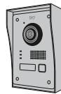
2.1 Exterior unit
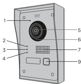
1 Microphone
2 Call indicator
3 Call in progress
4 Door open indicator
5 Camera
6 Infrared
7 Speaker
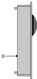
8 Anti-theft
9 Call button
2.2 Connectors
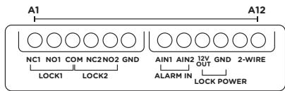
| A1 | NC1 | Normally Closed |
| A2 | NO1 | Normally Open |
| A3 | COM | Common |
| A4 | NC2 | Normally Closed |
| A5 | NO2 | Normally Open |
| A6 | GND | Neutral |
| A7 | AIN1 | Entrance alarm 1 |
| A8 | AIN2 | Entrance alarm 2 |
| A9 | 12V OUT | 12 V outlet for electric bolt |
| A10 | GND | Neutral |
| A11 | 2-WIRE | Power supply + (red) |
| A12 | 2-WIRE | Power supply - (black) |
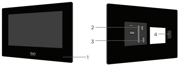
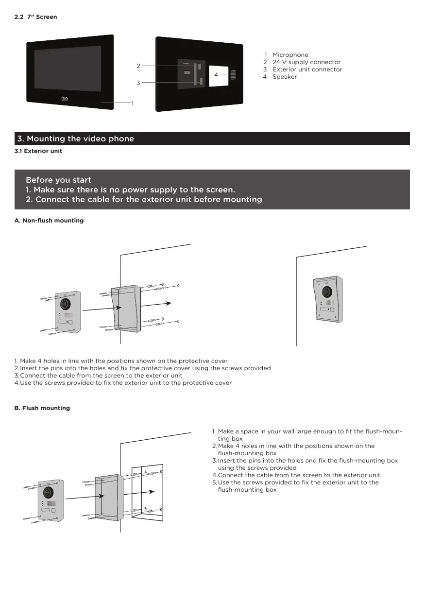
1 Microphone
2 24 V supply connector
3 Exterior unit connector
4 Speaker
3. Mounting the video phone
3.1 Exterior unit
Before you start
- Make sure there is no power supply to the screen.
- Connect the cable for the exterior unit before mounting
A. Non-flush mounting
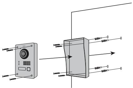
- Make 4 holes in line with the positions shown on the protective cover
2.Insert the pins into the holes and fix the protective cover using the screws provided
- Connect the cable from the screen to the exterior unit
4.Use the screws provided to fix the exterior unit to the protective cover
B. Flush mounting
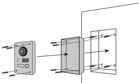
- Make a space in your wall large enough to fit the flush-mounting box
2.Make 4 holes in line with the positions shown on the flush-mounting box
- Insert the pins into the holes and fix the flush-mounting box using the screws provided
- Connect the cable from the screen to the exterior unit
5.Use the screws provided to fix the exterior unit to the flush-mounting box
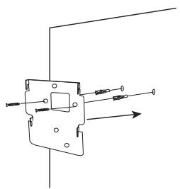
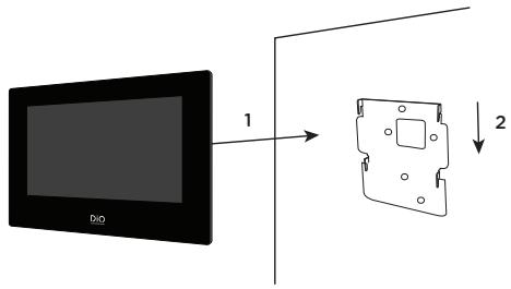
- Make 4 holes in line with the positions shown on the wall bracket
2.Insert the pins into the holes and fix the wall bracket using the screws provided
- Connect the power supply connectors and the connector for the exterior unit
4.Fix the screen to the wall bracket as shown in Figure 3.
4. Initial configuration
4.1 Configuration wizard
When you power the device up for the first time, an on-screen wizard will help you configure the important parameters for your video phone.
Please follow these steps before using the device.
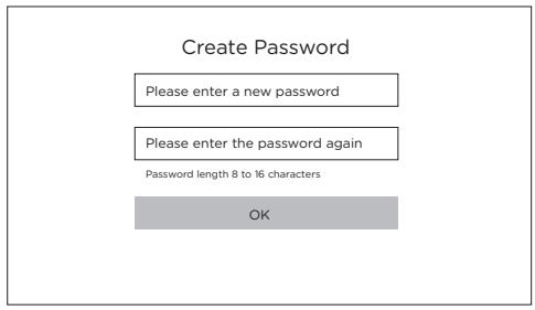
Step 1
Choose an administrator password in order to access the settings menu another time.
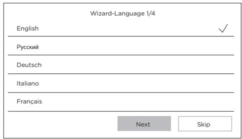
Step 2
Select your language
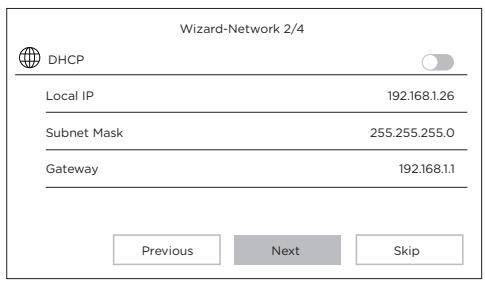
Step 3
Configure a local network between the interior and exterior units.
We advise that you do not select the DHCP option and you stick to the default settings.
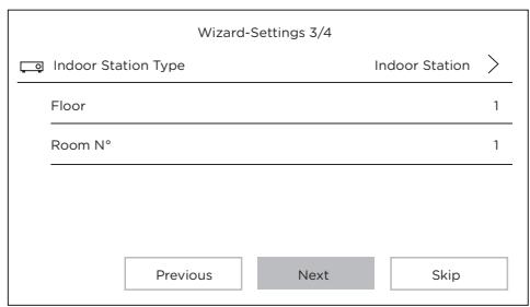
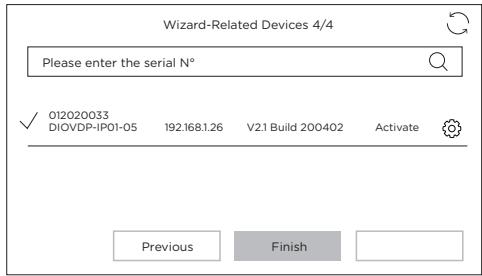
Step 4
You can find out the stage number and the unit number if you are installing multiple devices within a network.
This is optional.
4.2 Connection to the wireless network
You do not have to connect your unit to the wireless network. It is only used to add it into the smartphone app for remote control purposes.
Select the settings menu from the home screen

Then select the Wi-Fi icon from the left-hand menu

Select your network from the drop-down list
5. Installing the app
The application is available for Android and iOS.
Search for and install the "Guarding Vision" app on Android Play Store or Apple Store, depending on the model of your smartphone.
Open the application and create a user account by following the on-screen instructions.
5.1 Set-up via QR code
Select the settings menu from the home screen on your video phone monitor

Then select the configuration icon

Go to "Guarding Vision service parameters" to record the unit's QR code.
In the "Guarding Vision" app on your smartphone, select the "+" icon in the top right corner.
Select "Analyse code" from the drop-down menu.
Use your camera to scan the QR code on the video-phone screen.
5.2 Manual set-up
Select the settings menu from the home screen on your video phone monitor

Then select the configuration icon

Go to "Information on the device" to record the serial number of the device.
In the "Guarding Vision" app on your smartphone, select the "+" icon in the top right corner.
Select "Add manually" from the drop-down menu.
Enter the serial number shown on the screen of your video phone.
Note:
The default password for your device is 123456
The default verification code for your device is ABCDEF.
| General |
| Intercom type | 2 wires - hands-free |
| Operating temperatures | -40 ~ +55 °C |
| Storage temperature | -40 ~ +55 °C |
| Cable length and cross-section | from 0 to 100 m / section : 1.5 mm2 |
| Protection type (exterior unit) | IP65 |
| |
| Specifications |
| Trade mark Adapter | HOIOTO |
| Model identifier Adapter | ADS-40FSI-19 24036EPG |
| Input voltage | 100-240V |
| Input AC frequency | 50-60Hz |
| Output voltage | 24,0V DC |
| Output current | 1,5A |
| Output power | 36W |
| Average active efficiency | 80% |
| Efficiency at low load (10 %) | 76% |
| No-load power consumption | 4W |
| Consumption | Exterior unit <10W; Interior unit <8W |
| No. of rings | 3 |
| Speaking time | From 90s to 120s |
| Audio frequency | 500. - 8k. Hz |
| Screen type | 7" TFT LCD touchscreen |
| Screen resolution | 1024 X 600 Pixels |
| Camera type | 2MP Colour CMOS |
| Camera resolution | 1920 X 1080 Pixels |
| Door opening | 12V - 1A max (1-5 seconds) |
| Gate opening | Dry contact NO/NC (1 second) |
| WiFi encryption | WPA-PSK/WPA2-PSK |
| Security | AES128 |
| Protocols | TCP/IP ,RTSP, WIFI |
| Infrared | High power LED con ICR |
| Infrared distance | 3 Meters |
| Exterior unit | 1044g |
| Interior unit | 624g |

Direct current(DC)

Alternating current (AC)

Indoor use equipment

Class II equipment To identify equipment meeting the safety requirement specified for Class II equipment according to IEC 61140

Hereby, Chacon, declares that the radio equipment type 'DiOvDP-IPO1' is in compliance with the Directive 2014/53/EU.
The full test of the EU declaration of conformity is available at the following Internet address: http://chacon.com/conformity
7. Support
www.chacon.com/support