RECTANGULAIRE L.4.5 X L.2.5 X H.1.4 M - Pool UBBINK - Free user manual and instructions
Find the device manual for free RECTANGULAIRE L.4.5 X L.2.5 X H.1.4 M UBBINK in PDF.
User questions about RECTANGULAIRE L.4.5 X L.2.5 X H.1.4 M UBBINK
0 question about this device. Answer the ones you know or ask your own.
Ask a new question about this device
Download the instructions for your Pool in PDF format for free! Find your manual RECTANGULAIRE L.4.5 X L.2.5 X H.1.4 M - UBBINK and take your electronic device back in hand. On this page are published all the documents necessary for the use of your device. RECTANGULAIRE L.4.5 X L.2.5 X H.1.4 M by UBBINK.
USER MANUAL RECTANGULAIRE L.4.5 X L.2.5 X H.1.4 M UBBINK
Please read carefully and keep for future reference

- Maintenance and Safety Notice
FOREWORD
Wood, which is the main element used in building UBBINK® swimming pools, is a living substance and is liable to becoming warped if stored in adverse conditions. Make sure that you store all the wooden parts flat in a cool, well ventilated place, out of the sun and protected from bad weather.
- Whilst assembling the pool, make sure you sand down the catches on the wooden parts with a file or sandpaper in order to get rid of any potential splinters.
- Any cracks, knots and small faults on the surface of the strips do not in any way affect the wood's resistance. It certainly shouldn't be necessary to claim a replacement. Do not fill the cracks with putty or any other material.
- It is recommended that you have professional help when assembling the pool.
- The coping is a finishing element. It is strictly forbidden to run or sit on it.
- It is essential that the filter is installed below the level of the water;
SAFETY
The safety of your children is entirely your responsibility! The risk is greatest with children under 5 years old. Accidents do not just happen to other people! Be ready to deal with them!
be vigilant and take action:
- When using the swimming pool it is essential to comply with the safety procedures described in the handbook on maintenance and use. Failure to follow instructions regarding maintenance may endanger life, especially where children are concerned.
- children should be closely supervised at all times;
- designate one person to be responsible for safety;
have extra supervision when the pool is being used by several children; - make sure that there is equipment to keep anyone who cannot swim afloat;
- teach your children to swim as early as possible;
- wet your neck, arms and legs before getting into the water;
- learn life-saving techniques, especially those specifically used for children;
- do not allow diving or jumping in near young children;
- do not allow running or boisterous games around the edges of the pool;
- do not allow any child who is not a strong swimmer and is unaccompanied to get into the pool without a life jacket on;
- it is a good idea to remove the outside wooden ladder each time you have finished using your pool so that there is no unsupervised access;
- do not leave any toys near or in the pool if it is not being supervised;
- keep the water crystal clear and sanitised;
- store water treatment products out of reach of children;
- do not use any sharp or pointed object in the pool (which may damage the liner);
- never put treatment products directly into the water (this may cause staining on the liner);
- It is essential that the electrical appliances must be operated with an earth leakage circuit breaker (RCD) with a rated fault current of ≤ 30mA .
-
Do not allow anyone to go into the pool if the filtration system(s) is (are) not functioning properly.
-
All the filters conform to safety standard EN 60335-2-41 (France : NF C15-100) which stipulates that all electrical appliances installed at less than 3.5m from the pool and freely accessible must run on a very low power supply 12V. All electrical appliances that run on 220-240 VAC must be situated at least 3.5m (appliance) and 2,00m (plug) from the edge of the pool. Seek advice from the manufacturer regarding any changes to one or more elements of the filtration system.
- A Replacement of the net cable is not possible. In order to avoid any hazards, the electrical appliance must be taken out of operation in case the connecting cable gets damaged.
- Where possible check the bolts and screws (e.g. for any signs of rust).
- During the excavation phase make sure that the side walls are secured.
In your planning:
- the telephone should be positioned near the pool so that you can supervise your children whilst you are on the phone;
- an Inflatable ring and a pole should be kept near the pool;
- moreover, certain types of equipment may contribute to safety;
a) there should be a protective barrier with the gate always kept shut (e.g. a hedge cannot be regarded as a barrier); b) a manual or automatic cover should be correctly in place and secured;
c) an electronic detector which picks up anyone going in or falling in should be fitted and operating but this does not in any way replace close supervision;
If an accident occurs:
- get the child out of the water as fast as possible;
- call for help immediately and follow the advice you are given;
- remove wet clothing and wrap in warm blankets;
- memorise emergency numbers and put them on a notice near the pool :
- European emergency no: 112
- National Poisons Information Service
Leer atentamente y conservar para su consulta ulterior
PROLOGO
GARANTIES PISCINES UBBINK®
Piscine 250x450 - H140 cm Urban Pool
After Sales service UBBINK®
Pool 250x450 - H140 cm UrbanPool
Warranty conditions:
The pool must be assembled within 48 hours after opening the package. However, if you are forced to keep your pool unpacked for an indefinite period of time before installation (e.g. after-sales service request), it is essential to keep all wooden parts flat in a dry and ventilated area, and to restart them firmly to maintain the benefit of the warranty.
Assembly of the pool on a flat, smooth, level concrete slab in accordance with the dimensions indicated in the instructions is mandatory for the validation of the warranty.
- Our warranty is limited to the replacement of defective parts. It does not in any way imply a claim for compensation or damage and interest.
- The general warranty does not apply in the following cases:
- Use of equipment not in accordance with our instructions.
- Damage caused by improper handling during and after assembly or any modifications made to structural components without the manufacturer's consent.
The pump:
| UNDER WARRANTY | NOT UNDER WARRANTY |
| - Electrical problem: 2 years under normal use conditions (from the date of purchase of the consumer) | - Deterioration by abrasion or corrosion (particularly in the context of water treatment by salt electrolysis) - Damage due to faulty connection or improper replacement of the cable and/or power plug - Equipment dismantled or reassembled by a third party - Breakage of parts (pump base, prefilter cover, fluted tip...) - use of the dry pump - Damage to the pump due to its immersion (flooding of the technical room for example) - damage due to freezing |
The liner:
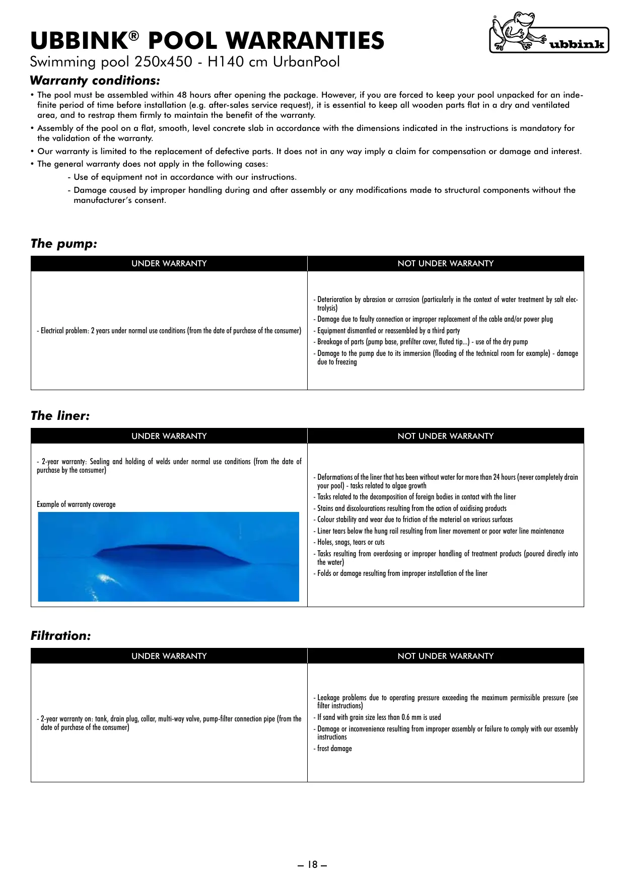
| UNDER WARRANTY | NOT UNDER WARRANTY |
| - 2-year warranty: Sealing and holding of welds under normal use conditions (from the date of purchase by the consumer)Example of warranty coverage | - Deformations of the liner that has been without water for more than 24 hours (never completely drain your pool) - tasks related to algae growth- Tasks related to the decomposition of foreign bodies in contact with the liner- Stains and discolourations resulting from the action of oxidising products- Colour stability and wear due to friction of the material on various surfaces- Liner tears below the hung rail resulting from liner movement or poor water line maintenance- Holes, snags, tears or cuts- Tasks resulting from overdosing or improper handling of treatment products (poured directly into the water)- Folds or damage resulting from improper installation of the liner |
Filtration:
| UNDER WARRANTY | NOT UNDER WARRANTY |
| - 2-year warranty on: tank, drain plug, collar, multi-way valve, pump-filter connection pipe (from the date of purchase of the consumer) | - Leakage problems due to operating pressure exceeding the maximum permissible pressure (see filter instructions) - If sand with grain size less than 0.6 mm is used - Damage or inconvenience resulting from improper assembly or failure to comply with our assembly instructions - frost damage |
Wood is a material that remains natural.
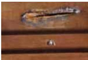
Wood is a natural material; it can have imperfections. A number of them are normal and superficial. They are excluded from the warranty because they do not affect the strength and durability of your pool.
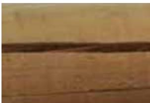
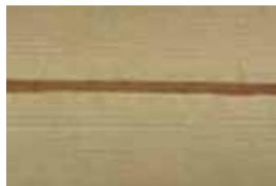
Cracks
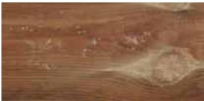
Resin
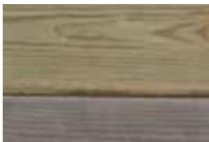
Shade differences
Longitudinal ribs and knots
Round knots
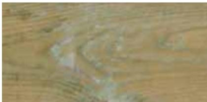
Retention of oven products
Surface mould
Cracks, splits and tears
Wood is subject to dimensional variations depending on humidity and temperature. When it dries, it retracts irregularly, causing cracks to appear. These can be impressive, but they do not affect the mechanical characteristics and strength of the product.
Resin upwelling
During the autoclave treatment of resinous species, the alternation of vacuum and pressure can lead to sticky resin residues on the surface of the wood. To remove them, simply scratch them gently with a suitable tool.
Colour differences
All wood species have variations in colour. Exposure of wood to UV rays will significantly attenuate them.
Presence of knots
The knots correspond to the trace of the branches of the tree. Our woods are selected to limit the quantity and size as much as possible.
Retention of oven products
Autoclave treated wood often shows greenish or whitish traces on the surface that disappear over time.
Surface mould
Woods are prone to mould caused by microscopic fungi. This surface phenomenon, reinforced by heat, humidity and lack of ventilation, is characterised by spots ranging from light blue to black blue. A simple wiping or exposure of the wood to the outside makes it easy to remove them. It should be remembered that treated woods in class 4 are of course protected against fungal attack.
Additional processing
No additional treatment or application of a wood preservative for your Ubbink® pool is required. When exposed to UV rays, the wood will turn grey over time without affecting its durability. However, you can apply a microporous stain compatible with the autoclave treatment to preserve its original colour if you wish.
Storage and assembly of your pool
If you do not wish to install your pool immediately, it is necessary to store your package properly, without unpacking it, in a cool and well-ventilated place, or failing that, protected from the elements and the sun. If, however, you are forced to unpack your pool, it would be imperative to recondition the package, flat beams, and restrap it firmly. Once unpacked, the structure must be assembled within 48/72 hours.
UNDER WARRANTY
- 15-year warranty against rot and attack by wood-boring insects (from the date of purchase by the consumer) when installed on a smooth, level concrete slab
NOT UNDER WARRANTY
- Changes in wood colour due to climatic effects
- Natural deformations (cracks, splits, and knots that do not affect the mechanical resistance of the wood in any way)
- Imperfections that do not affect the solidity of the structure: resin build-up, difference in colour of the beams, retention of proofer products giving the wood a greenish appearance and grey/black surface mould resulting from a lack of ventilation of the packaged structure
- Assembly or storage defects resulting in deformation of the wall slats (assembly carried out long after opening the package without restrapping)
- Deformation of the beams caused by water pressure, which does not alter the mechanical resistance of the pool in any way
- Deformation of the structure resulting from non-compliant slab assembly
- Deterioration of the structure resulting from semi-underground or non-compliant underground installation (waterproofing sheet and gravel backfill mandatory)
- Structural degradation resulting from treatment of the wood with aquaphobic products that do not allow the wood to breathe: tar, varnish, glaze....
- Breaks or missing tabs of less than 30~cm that do not affect the mechanical resistance of the pool
- Slight deformations that do not prevent the interlocking of the beams
UBBINK® After-Sales Service
Swimming pool 250x450 - H140 cm UrbanPool
IMPORTANT: After-sales service will only be processed with points of sale.
- Mandatory parts to apply the warranty:
Checkout ticket/proofof purchase
Photo of the damaged part or problem encountered
Warranty form below duly completed
Serial number
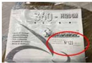
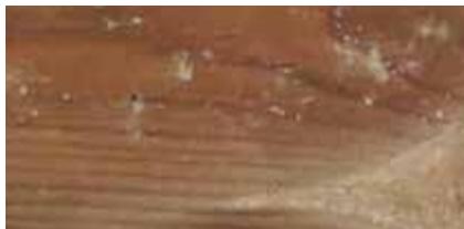
Example of a structural problem:
No. appearing on notice
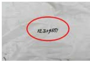
No. appearing on white tarpaulin
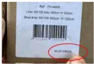
Example of a liner problem:
No. appearing on packaging board
| Store: | Client: |
| City: | Address: |
| Contact: | City: |
| Direct phone: | Tel: |
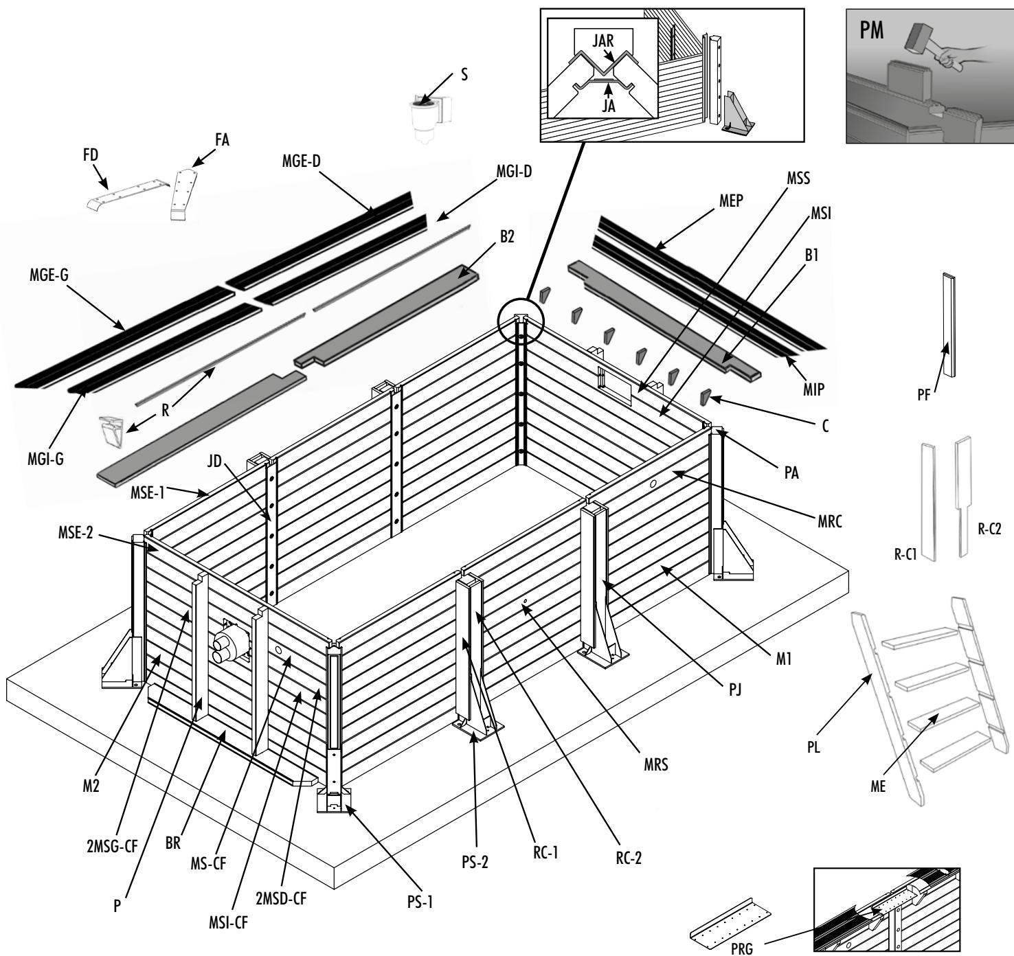
Parts list:
| Code | Ref. | Designation | Service Qty | SAV Qty |
| PL | 7100201 | Pair of rungs for wooden ladder H120/130 cm | 1 | |
| M1 | 7514854 | Beam 45 x 145 x 145 x 1310 mm | 52 | |
| M2 | 7514855 | Beam 45 x 145 x 145 x 1980 mm | 14 | |
| MSE-1 | 7514856 | Upper beam 45 x 135 x 1310 mm | 6 | |
| MSE-2 | 7514857 | Upper beam 45 x 135 x 1980 mm | 1 | |
| MSS | 7514871 | Upper skimmer beam 45 x 135 x 1980 mm | 1 | |
| MSI | 7514872 | Lower skimmer beam 45 x 145 x 1908 mm | 1 | |
| MS-CF | 7514873 | Upper counter flow beam + skimmer discharge 45 x 145 x 1980 mm | 1 | |
| 2MSD-CF | 7514874 | 1/2 straight beam swims against the current 45 x 145 x 852.5 mm | 1 | |
| 2MSG-CF | 7514875 | 1/2 left beam swims against the current 45 x 145 x 852.5 mm | 1 | |
| MSI-CF | 7514876 | Lower beam swims against the current 45 x 145 x 1980 mm | 1 | |
| MRC | 7514877 | Beam with brush socket 45 x 145 x 1310 mm | 1 | |
| MRS | 7514878 | Pool spotlight beam 45 x 145 x 145 x 1310 mm | 1 | |
| PA | 7514260 | Corner post P1 100x115x1288 mm | 4 | |
| PJ | 7504340 | Connecting post P2 100x120x1288 mm | 4 | |
| B-1 | 7514879 | Notched basting 45 x 170 x 2428 mm | 2 | |
| B-2 | 7514880 | Notched basting 45 x 170 x 2214 mm | 4 | |
| BR | 7514882 | Bottom basting for wall reinforcement 45 x 170 x 1745 mm | 2 | |
| P | 7514881 | Reinforcing post 45 x 135 x 1350 mm | 4 | |
| PS-1 | 7504346 | Galvanised steel support plate 300 x 255 mm | 4 | |
| PS-2 | 7504380 | Galvanised steel support plate 300 x 255 x 1153 mm | 4 | |
| R-C1 | 7514944 | Wooden covering, side part 1218 x 145 x 22 mm | 8 | |
| R-C2 | 7514945 | Wooden covering, central part 1218 x 115 x 22 mm | 4 | |
| JA | 7504347 | Corner joint galvanised steel 100 x 1312 mm | 4 | |
| JAR | 7514258 | Corner connection reinforcement galvanised steel 119 x 1288 mm | 4 | |
| JD | 7504348 | Right-hand connection galvanised steel 118 x 1312 mm | 4 | |
| PF | 7504358 | Finishing profile 850 x 60 x 60 x 10 mm | 4 | |
| PRG | 7514889 | Galvanised reinforcement profile | 2 | |
| MEP | 7514883 | Outer edge small 27 x 145 x 2478 mm | 2 | |
| MIP | 7514884 | Small inner edge 27 x 145 x 145 x 2188 int. | 2 | |
| MGE-D | 7514885 | Outer edge right 27 x 145 x 2239 mm 45° angle | 2 | |
| MGE-G | 7514886 | Outer edge left 27 x 145 x 2239 mm 45° angle | 2 | |
| MGI-D | 7514887 | Right inner edge 27 x 145 x 2094 mm 45° angle | 2 | |
| MGI-G | 7514888 | Left inner edge 27 x 145 x 2094 mm 45° angle | 2 | |
| R | 7514016 | Hung hanging rails 2.06 ml | 6 | |
| C | 7514048 | Bracket 45 x 230 x 145 x 170 mm | 17 | |
| ME | 7514052 | Step 28x145x600 mm | 4 | |
| PM | 7514114 | Martyr piece 45x135x280 mm | 2 | |
| 7514149 | Sand bag (25 kg) | 3 | ||
| 7514750 | Stainless steel ladder 3 steps | 1 |
| 7504297 | Poolmax TP50 pump - 0.37 kw - 0.50 HP - Qmax 12,600 l/h | 1 | ||
| 7514704 | PoolFilter Sand filterø400 mm-flow 17m³/h - 3.5 bar - cap. 50kg - 6 ways | 1 |
| Code | Ref. | Designation | Service Qty | SAV Qty |
| S | 7514019 | Skimmer wide vent incl. discharge nozzle | 1 | |
| 7514024 | Protective felt pool wall 170gt/m2 - L 1.35 x W 15.3 m | 1 | ||
| 7514822 | Floor protection felt for swimming pool 200gt/m2 - L 2.00 x W 5.0 m | 1 | ||
| 7514147 | Brush plug assembly for wide and narrow skimmer vents | 1 | ||
| FA | 7514758 | 4-piece aluminium 45d coping stone finishing kit incl. hardware for fixing - rectangular pool | 4 | |
| FD | 7514829 | Straight anodised aluminium rectangular pool edge finish | 2 | |
| 7514753 | Set of 2 anchors for rectangular pool ladder support | 1 |
| 7514891 | Mounting plate for jetsstream | 1 | ||
| 7514892 | Jetstream housing unit | 1 | ||
| 7514894 | Jetstream pump, 2.5HP, 230 V AC~50Hz | 1 | ||
| 7514893 | Jetstream control unit | 1 | ||
| 7514896 | Urban Pool® electrical box | 1 | ||
| 7504615 | Pool spotlight 350 LED Plus | 1 | ||
| 7505523 | Heatermax INVERTER 20 | 1 | ||
| 7514895 | PVC jetsstream plumbing kit + Heatermax INVERTER 20 | 1 | ||
| 7514208 | Plumbing kit | 1 | ||
| 7514302 | PVC pipes, Ø 50 mm, 1 m | 8 | ||
| 7514673 | Finishing profile for liner rails (m) | 19 | ||
| 7514129 | Hose, 25 m, Ø 50 mm | 1 |
| 7514831 | Hardware kit | 1 | ||
| Code | Réf. | DETAIL OF THE KIT QUNCAILLERIE | Service Qty | SAV Qty |
| A1 | 7514516 | Bracket bag + reinforcements - 6 x 90 Torx screws | 3 | |
| A3 | 7514638 | Bracket bag + reinforcements - 6 x 90 Torx screws | 1 | |
| C2 | 7514639 | Rail bag - hung - 4 x 40 screws | 1 | |
| DMP2 | 7514618 | Bag of coping stone screws - 5 x 50 Torx screws | 2 | |
| J1 | 7504411 | Bag for fixing posts - bolts + nuts 12 x 160 | 1 | |
| K3 | 7514847 | Bag for fixing posts - bolts + nuts 12 x 120 | 1 | |
| P1 | 7514273 | Metal shoe fixing bag - anchoring studs 20 x 160 + caps | 1 | |
| P3 | 7514938 | Metal shoe fixing bag - anchoring studs 8 x 90 + caps | 1 | |
| N | 7514275 | Wooden ladder bag | 1 | |
| M | 7514276 | Fastening bag for wooden cover boards - nails 2.3 x 45 | 1 | |
| T1 | 7514935 | Bag of galvanised reinforcement profile screws - screws 5 x 40 Torx | 2 |
| 7514833 | Liner 75/100 blue 250 x 450 - H140 cm | 1 | ||
| or | ||||
| 7514907 | Liner 75/100 beige 250 x 450 - H140 cm | 1 | ||
| or | ||||
| 7514908 | Liner 75/100 grey 250 x 450 - H140 cm | 1 | ||
GARANTÍA DE LAS PISCINAS UBBINK®
Piscina 250x450 - A140 cm UrbanPool
- In-ground installation (on concrete slab)
NOTE: Compulsory safety equipment (tarpaulin, alarm, barrier...)
- Key points on the partially sunk swimming pool or on the inground installation
Before you begin to assemble the pool, make sure that you have all the necessary parts.
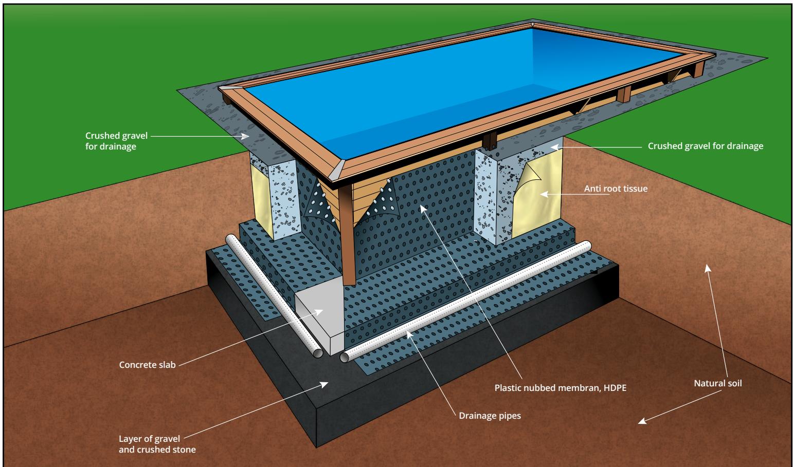
IMPORTANT: If you choose to partially sink your swimming pool, make sure that you embed the pump and the filtration unit at the same level as the pool in an enclosed, waterproof place. To ensure that the filtration unit works efficiently, it must always be positioned below the level of the water.
CAUTION: In the case of a partially sunk swimming pool, before you put any water into the pool, you must have a safety system in place for the prevention of drowning, which complies with your national safety standards

During the excavation phase make sure that the side walls are secured.

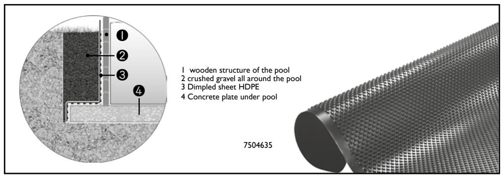
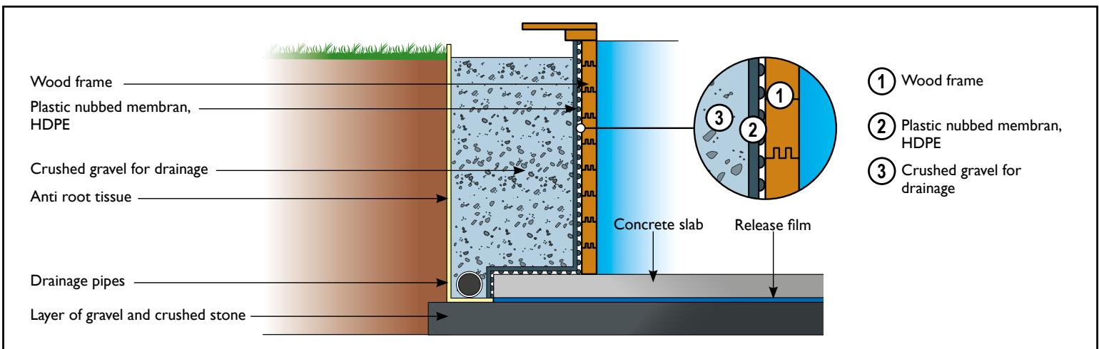
- Install the waterproofing sheet (not provided) on the outer sides of the pool to drain off rainwater. The height of the liner must correspond to the level of the bank of gravel.
- The dimpled side is to be placed against the pool structure, leaving an air gap between the wet slope and the pool walls. The dimpled structure provides for a convenient distribution of the slope pressure, und at the same time for a low point load (compressive strength: 250kN / m^2 )
- Fill the pool with water before backfilling the circumference with gravel. Fill the circumference of the pool with gravel. Be careful not to distort the structure when backfilling.
Before starting the assembly, make sure that you have all the necessary parts by taking an inventory from the parts list provided on page 9.
- Installation on concrete slab is mandatory and imperative for warranty validation. Thickness: 20 cm minimum. Make sure that the slab is perfectly flat, smooth and level.
SUMMARY:
1 - Wall assembly
- Installation of reinforcements and brackets
- Preparation of the walls
4 - Installation of bottom felt and liner
- Cutting out the jetstream installation
- Cutting out the discharge nozzles, brush and skimmer plugs
7 - Cutting and installing the spotlight
8 - Installing the coping stones and anodised aluminium finish
9 - Ladders
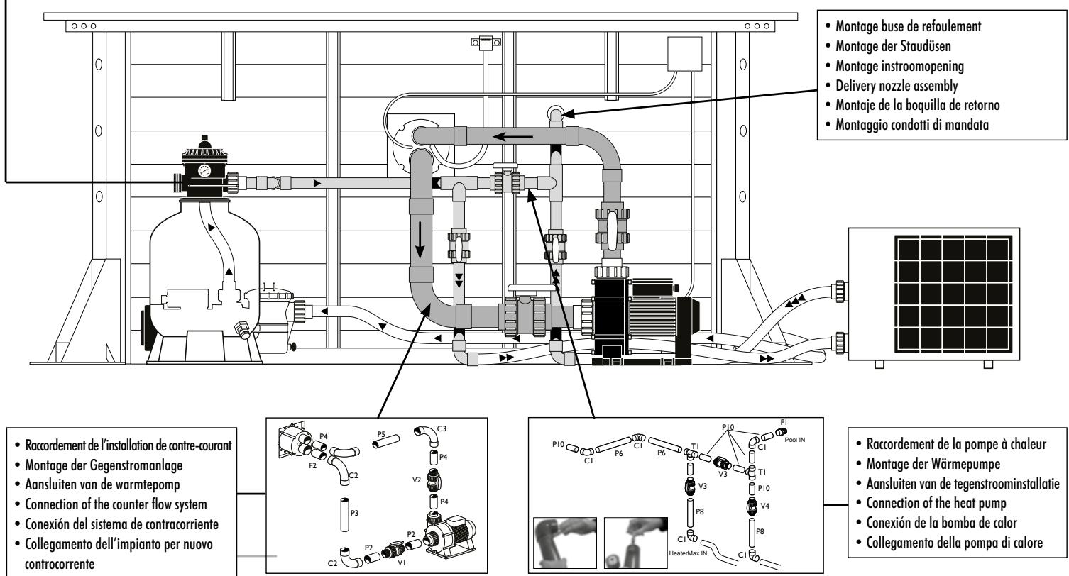
10 - Connecting the jetstream system
- Connecting the filter system
12 - Connecting the heat pump
- Connecting the automatic pool floor vacuum cleaner (The pool vacuum cleaner is optional. It is not included in the equipment provided.)
14 - Electrical cabinet
15 - Using the jetstream installation
All the instructions in the present operating manual that refer to electrical installations (electrical box, counter-current system, filtration system, swimming pool spotlight and heat pump) must be performed only by a qualified electrician.
Wall assembly
- Align the pool so as to position the entrance of the skimmer(s) facing the prevailing winds in order to optimise the evacuation of surface particles.
I a - Place the wooden posts in the metal bases.There are short (PS1) and long (PS2) metal bases, make sure they are in the right positions!
Ib - Retrofit the first row of beams. The tabs are intended to correctly align the beams when they are interlocked; their absence or small breaks do not in any way affect the mechanical resistance of the wood, the solidity and the assembly of the pool.
Ic - Secure these beams in place using the metal studs (corner and right). Fasten with the bottom bolt 12 × 160 loosely. Position the assembly of the bolts of the J and K bag: 12 × 160 for the metal bases and 12 × 120 in the upper part of the posts.
Id - Continue assembling the beams using the martyr piece provided for this purpose.
Ie - If - Place the jetstream beams on rows 6/7/8 in front of the skimmer. Place the lower and upper skimmer beams on the 9/10 rows in front of the jetstream. Place the pool spotlight beam in the 6th row on a wall to the left or right of the skimmer. Place the beam in the 8th row on a wall to the left or right of the skimmer.
Ig - Put the remaining beams in place.
Ih - Check the alignment of the lower and upper skimmer beams as well as those of the jetstream.
Ii - Check the alignment of the shoes (chalk line) and diagonals (10 m tape); A = B
lj - Tighten all bolts on all posts.
Ik - Prepare the drilling of the upper beams, respecting the dimensions.
11 - Drill the central hole (diam. 8 mm), strike the first anchor pin 8 × 90 and tighten. Drill the remaining holes (diam. 20 mm), strike the 20 × 160 anchor bolts and tighten. Repeat the operation on each base.
Im - Nail the finishing boards to the posts. Do the same for RC-1 and RC-2 wood flooring.
Installing reinforcements and brackets
2a - Start by fixing the supplied PRG metal plate below the support boards with the screws. Position the horizontal reinforcements flush with the top edge to the outside of the structure. Level and screw in from inside the pool until the screw heads are drowned.
2b - Pre-drill 3 holes diameter 6mm (on the corners).
2c - Enlarge the holes to a depth of 45mm using a 12mm diameter flat drill bit and screw in using 3 6x90 screws.
2d - Pre-drill 3 holes of diameter 6mm and screw to the junctions using 3 screws 6× 90
2e - Position the brackets in the up-down direction, draw their positions, drill and screw until the screw heads are drowned.
2f - Screw the horizontal reinforcement with the brackets.es.
Preparation of the walls
3a - Screw the skimmer vent into the upper beam using 2 round head screws to be removed from the screw bag provided in the skimmer box.
3b - Install the skimmer square outer seal and the skimmer body.
3c - Secure the assembly with the 8 round head screws to be removed from the screw bag provided in the skimmer box, tightening effectively for a good waterproofing. (Screw in by hand).
3d - Seals. Place a rectangular joint on the skimmer frame, making sure it adheres well. At the outlet and the brush socket, install the cork seal (A) in contact with the wall and then superimpose one of the 2 white round joints (B), making sure that they adhere well.
3e - Screw the jetstream installation fixing plate fully onto the milled frame using the 244 × 35 mm stainless steel screws provided.
3f - Drill the rails to size (3 cm from the ends and then every 20 cm approximately). The rail of a wall can be composed of several segments placed end to end.
3g - Unroll the wall felt.
Before the next step, carefully clean the concrete slab and remove shards or splinters from the walls with abrasive paper to make all supports clean and smooth.
3h- Attach the plastic rail to the felt underlay of the top plank.
3i - Screw on the first liner rail using the 4 × 40 stainless steel screws.
3j - At the corners, partially cut into the rail in a "V" shape, so that the profile can be folded. Screw at 3 cm from the corner on both sides, then screw on all the rails.
3k - Cut the felt on the outside of the frame.
31 - Do the same with the return flow, vacuum point and counter-current swimming system frame.
3m - Install the counter-current swimming system body on the mounting plate using the 5x20 stainless steel screws, washers and nuts supplied.
Note: The counter-current system housing must be installed such that the outlet of 75 mm is positioned higher and the suction of 90 mm is positioned lower. 10C page 52.
4
Felt and liner installation
4a - Install the protective felt for the floor.
4b - Cut the protective felt with a cutter or a pair of scissors.
4c - Place the liner in place at an outside temperature between 20 and 25^ .
4d - Match the corners of the liner with the bottom corners of the pool.
4e - Hang the liner in the lip of the rail.
4f - Position the locking ring all around the pool. Start in the middle of the wall.
4g - Stretch the liner to the maximum.
4h - Put in 2 cm of water.
4i - Remove existing folds and fill the pool with water up to 5 cm below the jetstream installation.
5
Cutting the liner and jetstream installation
5a - Install the gasket and jetstream frame using the stainless steel screws provided.
5b - Cut the liner inside the jetstream frame.
5c - Connect the air mixing hose to the front and rear parts of the jetstream box. Insert the hose into the air inlet socket. Secure with a hose clamp. Cut the air hose to the correct length.
5d - Attach the pneumatic hose to the opening provided for this purpose in the jetstream system and connect it to the socket of the PN button (switching the pump on and off). Tighten the hose by hand on the pneumatic switch and on the jetstream housing.
5e - Insert the entire front cover into the jetstream housing and screw in the unit with the 4 stainless steel screws provided.
6
Cutting of discharge nozzle, brush and skimmer socket
6a - Position the discharge nozzle and brush plug from inside the pool.
6b - Cut the liner at the discharge nozzle and brush socket, leaving a gap of about 2mm . Insert the white seals (B), the nozzle and the brush plug.
6c - Tighten the outer nuts of the discharge nozzle and brush plug sufficiently to ensure tightness by means of the trick, if necessary mentioned on the diagram
6d - Cover the threaded part of the end caps with Teflon tape in a counter-clockwise direction.
6e - Screw the end caps onto the delivery and brush socket.
6f - Example of pipe positioning at the skimmer and brush socket
6g - Brush socket - discharge nozzle Glue the elbow, shut-off valve, corresponding connection and PVC pipes cut to length according to the ground configuration.
6h - Glue the previously assembled assembly to the outlet of the brush socket and discharge nozzle. Close the shut-off valves.
6i - After covering the Teflon threaded part, screw the threaded stop valve into the skimmer body.
6j - Glue the rigid PVC pipe and elbow to the stop valve. Close the valve after the gluing has set and refill the basin to 5 cm below the beams.
6k - Install the gasket and skimmer frame.
61 - Screw the skimmer assembly together using the 18 flat head screws to be removed from the screw bag provided in the skimmer box.
6m - Cut the liner inside the skimmer frame. Finally, place the flange cover by clipping it into place.
6n - Correct water level at mid-height of the skimmer.
7
Mounting the spotlight
7a - Insert the screws into the 4 holes in the front of the assembly frame and slide the silicone gaskets over the screws on the back.
7b - After drilling the liner and beam with a 0.25mm drill bit, screw the assembly frame vertically at a distance of 50mm to the right or left of the hole, ensuring that the silicone seals are correctly positioned.
7c - Unscrew the fixing nut of the cable bushing and remove it from the cable.
7d - Insert the lamp cable into the liner hole and pull it out. Then carefully push the cable feed-through into the liner hole and push it as far as it will go, making sure that the white seal is in contact with the liner.
7e - Then slide the fixing nut onto the lamp cable and screw it onto the cable feed-through. If you are using a universal wrench or pliers, make sure that you do not overtighten or damage the nut.
7f - Wind the necessary length of cable to pull the spotlight out of the water.
7g - Unscrew the black nut and tighten the cable outside the pool. Position the pool spotlight so that the word «TOP» on the front ring is above and insert the fixing screw into the top hole. Then tighten the lower screw at the bottom of the spotlight.
Be sure to follow the instructions for use given in the instructions accompanying the spotlight.
8
Installation of the pine coping stones.
the coping stone is a finishing element. It is strictly forbidden to walk, run or sit on it. Are not covered by warranty: colour changes, deformations (cracks, fissures, checks, knots or splinters) natural or resulting from improper installation.
8a - Pre-drill the inner coping stones approximately every 70 cm and screw them in. Start at least 3 cm from the ends.
8b - Pre-drill the outer edges.
8c - Screw in the outer coping stones.
8d - Position the corner and straight plates. Pre-drill and screw in using 6x30 screws.
9
Ladders
The use of ladders must be limited to access to the pool
The maximum weight allowed is 150kg The pool ladder must be placed in a safe position when not in use..
9a - Retrofit the ladder. To do this, flush the air below the steps if necessary.
9b - Mark the location of the ladder fasteners.
9c - Drill the coping stone and reinforcement with a 0.50mm hole saw. Identify the location of the bracket fixing screws and drill holes.
9d - Place the bracket in the hole and secure with two 6x60 screws.
9e - Position the wooden ladder against the horizontal reinforcement below the coping.
9f - Locate and drill the holes.
9g - Mark the locations of each bolt on each of the rungs and drill holes to lock the ladder.
10
Connecting and using the jetstream system
CAUTION!

-
The electrical connection of the pump and the jetstream control unit must be carried out by a qualified electrician.
-
The power supply must be disconnected with the differential circuit breaker (Fl) before any work is carried out on the unit.
10a - Mount the PVC pipes and fittings as shown in the illustration. Note: Before gluing, first proceed with a dry assembly to check that all parts fit together.
- Clean the hose and connecting parts with the paint stripper.
- Do not use abrasive paper to clean the smooth PVC pipe.
After cleaning, the surface must be matt. Do not touch the surface again as soon as it has been cleaned.
- Apply the adhesive along the longitudinal axis of the pipe and the connecting pieces.
- Assemble the two parts after applying the glue. Insert the parts fully into each other without turning them and hold them together for a few
moments.
- Then remove the excess glue with a brush.
- Do not use the glue at temperatures below 5^ . The assembly must be done quickly.
10b - Connect the pneumatic hose to the electro-pneumatic box. Be careful not to bend the hose.
10c - Connect and fix the air hose to the outer housing of the jetstream using the hose clamp and mount its check valve to the wall outside the pool.
Be sure to follow the instructions for use given in the instructions accompanying the jetstream kit.
- The electrical connection of the filter pump must be made by a qualified electrician.
The power supply must be disconnected with the differential circuit breaker (Fl) before any work is carried out on the unit.
Ila - Mount the pool filter according to the instructions for use.
I I b - Example of sand filtration installation.
Be sure to follow the instructions for use given in the instructions accompanying the sand filtration kit.

Connecting the heat pump to the sand filtration kit
12a - Mount the PVC pipes and fittings as shown in the illustration. Note: Before gluing, first proceed with a dry assembly to check that all parts fit together.
- Clean the hose and connecting parts with the paint stripper.
- Do not use abrasive paper to clean the smooth PVC pipe.
After cleaning, the surface must be matt. Do not touch the surface again as soon as it has been cleaned. - Apply the adhesive along the longitudinal axis of the pipe and the connecting pieces.
- Assemble the two parts after applying the glue. Insert the parts fully into each other without turning them and hold them together for a few moments.
- Then remove the excess glue with a brush.
12b - Set the by-pass for operation
- For operation with the heat pump: Open valves 1 and 3, close valve 2.
- For operation without the heat pump: Open valve 2, close valves I and 3, as shown in diagram 12b on page 54.
Be sure to comply with the operating instructions given in the instructions accompanying the heat pump.

Connection of the automatic bottom vacuum cleaner - the Poolcleaner vacuum cleaner is optional. It is not included in the equipment provided
13a - Insert the pressure regulator into the rubber adapter. Make sure the direction is correct.
13b - Reassemble the automatic brush hose and connect it to the free end of the pressure regulator. It is important to purge it of air. Plug in the assembly kept immersed in the brush socket. Open the shut-off valve of the brush socket and close the one of the skimmer. Switch on the pump. If the brush is not used, close the shut-off valve of the brush socket and open the one of the skimmer. Refer to the automatic broom manual for more details.

Electrical cabinet CAUTION!
- The installation of the electrical box as well as the connection of the filtration pump, the heat pump, the control unit of the jetstream and the pool lighting must be carried out by a qualified electrician.
The power supply to the box must be disconnected with the differential circuit breaker (Fl) before any work is carried out on the unit.
- The electrical box must not be used as a junction box for connections outside the system.
14a - Have the filter pump, heat pump, jetstream control unit and lighting of the pool connected by a qualified electrician.
14b - Set the analogue timers for the filter pump and pool lighting to the hour by turning the minute hand in the direction of the arrow.
14c - The selection switch on both timers allows you to manually turn the filtration pump and pool lighting on and off or to order them by defining schedules. In the ring area, the times for which you want to set the times are displayed. Push the teeth whose power supply must be cut inwards, the remaining teeth on the outside now represent the time at which the power supply must remain active.
| I | Illuminated |
| ① | timer |
| O | Off |
In the ring area, the times for which you want to set the times are displayed. Push the teeth whose power supply is to be cut inwards, the remaining teeth on the outside now represent the time at which the power supply is to remain active.

Use of the jetstream installation
CAUTION!

- Only start up the system when the tank is full. It is essential to avoid any dry running of the pump.
15a - Fill the basin with water up to half the maximum skimmer height.
15b - Open both slides and switch on the system with the PN switch
15c - Adjust the water flow by turning the front inner nozzle. The maximum water flow is obtained by turning the nozzle to the left. Turn the nozzle to the right to reduce it.

maximum flow rate minimum flow rate
15d - Adjust the air addition by turning the front outer nozzle.
15e - Adjust the nozzle to a jet so that the float is opposed to the maximum jet.
Troubleshooting instructions
| Problem | Possible cause | Recommended action |
| The pump makes a lot of noise with-hout providing normal power. | The engine is running in the wrong direction. | Reverse the motor poles by exchanging the phases |
| The water level is not high enough. | Add water. | |
| The pump sucks in air. | Check that the connections do not leak. | |
| The slide is not fully open. | Open the slide. | |
| The suction pipe is not watertight. | Seal the suction pipe. | |
| The pump is blocked (by leaves etc.). | Clean the pump. | |
| The pump makes a lot of noise and provides maximum power. | Friction of the engine cover. | Fix it correctly. |
| The fan cover is too loose. | Fix it correctly. | |
| The pump does not start or starts slowly and with difficulty. | A phase is missing. | Modify the power supply. |
| The FI switch reacts during ignition | Bad fuses | Use a 16A time delay fuse |
| Have the installation checked by an electrician. | ||
| The engine safety switch turns off. | Incorrect setting. | Set the correct electrical value by +10%. |
| The pump overheats. | Allow the engine to cool and restart it. | |
| A phase has been skipped. | Check the fuse. | |
| The pump cannot be switched on from the tank. | The switch pipe is bent or jammed. | Check that the pump can be switched on from the electrical box. |
| Switching hose too long. | Switching hose too short. | |
| Fuses/power supply/power supply/motor safety switch | Check the fuses/power supply/test the motor safety switch | |
RESUMEN:
- WASTE outflow = sewer
Salida WASTE = Desagues - Uscita WASTE = Scarichi
UTILISATION ET ENTRETIEN DES PISCINES BOIS
(1) Failure to comply with the maintenance instructions may lead to serious risks to health, particularly where children are concerned.
1. TREATING THE WATER
Your swimming pool installation is complete! Before you get into the pool for the first time, it is essential to "prepare" the water. Bathing often leads to a good deal of pollution caused by things like vegetation, earth, dust, sweat, saliva, hair, grease, etc. The swimming pool water must be protected from these substances in order to avoid various micro-organisms developing.
In order to do this, a few simple rules may be applied:
- It is a good idea to have the filter running during the day, as it is bathing that causes most of the pollution. Regulate the timing of the filter according to the temperature of the water. The higher the temperature of the water, the more easily bacteria will grow.
| Water Temperature | < 10° | 10-12° | 12-16° | 16-24° | 24-27° | 27-30° |
| Filtration time | 2h | 4h | 6h | 8h | 10-12h | -> 20h |
Generally speaking, whatever type of system you have, any impurities should be removed if the pool is cleaned regularly using the filter.
The sand filter: When the amount of impurities in the sand increases, the circulation of the water becomes less efficient and consequently the pressure increases. Refer to the notes on maintaining the filtration unit for cleaning it.
-
Analyse the water in your swimming pool: it is a worth checking the pH level (degree of acidity or alkalinity of the water) every week. It should always range between 7.2 and 7.6. An incorrect pH level may result in the water treatment products working less efficiently, may accelerate the development of chloramines (causing unpleasant odours and irritation of the mucous membranes...) and the corrosion of any metal parts..
-
Treat the water regularly: a weekly disinfectant treatment (bromine, chlorine and active oxygen...) against bacteria will avoid all the problems caused by poor quality water. One treatment every fortnight with an algaecide effectively combats the initial appearance and further development of algae.
(1) Using and storing chlorinated products
Remember that these are dangerous products that must be stored and used only as directed by the manufacturers. Do not mix chemical products with each other. Store products in tightly closed containers in a cool and well ventilated place; do not expose to direct sunlight. If using a container for measuring out chemicals, rinse thoroughly after each use. Read the safety information and instructions provided on each label carefully. Keep all chemicals out of reach of children..
- Everyday remove as much dirty matter from the pool as possible with a fishing net (fallen leaves, dead insects...) and clean the surface of the water regularly to remove greasy deposits.
- Empty the pump container. Just like the skimmer container, it is a good idea to empty it regularly to maintain the optimum filtration level.
Annual treatment: In order to have clean water all the time, clean the filter, change about to 12 of the water in the pool and look after it properly through the winter. Change all the water in your pool every 3 to 4 years.
Problems and solutions :
| PROBLEMS | CAUSES | SOLUTIONS |
| 1. Water clear with greenish or brownish tint. Large number of brown stains on the sides of the pool. | Oxidation of metallic salts (iron or copper) present in the water used to fill the pool | Check the pH level. Put in a calcium and metal stabiliser when you fill the pool. Clean out the filter. Remove sediment and filter continuously. |
| pH level too low. Corrosion of metal parts. | ||
| 2. Water has a yellow or brownish tint | Water being used to fill the pool is high in iron or manganese | See 1. |
| 3. Water milky and cloudy | Organic and colloidal impurities | Chlorinate thoroughly. Clean the filter. Remove sediment and filter well. |
| Inorganic substancesincreasing the hardness of the water | Check the pH level. Put in a calcium and metal stabiliser when you fill the pool. | |
| 4. Slimy green deposits on the sides of the pool | Build up of algae | Chlorinate thoroughly. Treat with an algaecide |
| 5. Sides of the pool have an uneven appearance | Calcium deposits caused by hard water | Check the pH level. Put in a calcium and metal stabiliser. If the pool is empty clean with a pool descaler. |
| 6. Irritation to skin and eyes, unpleasant odour | Presence of combined chlorine (chloramine) | Adjust the pH level. Chlorinate thoroughly. Put in fresh water |
| 7. Evidence of corrosion | pH level too low | Increase the pH level to 7.0 - 7.4 |
2. TAKING CARE OF THE STRUCTURE OF THE POOL
- The wood
Wood is a living substance which is subject to variations in humidity and temperature. Over the course of time wood is liable to swell, tiny cracks or splits may appear. Such occurrences do not in any way alter the wood's resistance or the durability of our materials.
Furthermore, a deformity in the sides of the pool caused by the pressure of the water may occur, mainly on the central and lower planks (under maximum water pressure) - this is normal.
On the understanding that the pool has been assembled according to the instructions provided, there is no cause for concern here regarding the stability of the structure.
The sterilising high pressure steam treatment of all the timber parts protects the wood from being attacked by insects and fungi. This treatment gives the timber a greenish hue which does not pose any danger to humans. At any rate, this colour will fade with time. According to how much it is exposed to direct sunlight, the wood will gradually take on a silvery grey appearance. This process can be slowed down by using a glaze or protective oil, which ideally should be applied a few weeks after the swimming pool has been installed (this will stabilise the structure and reduce the greenish tinge caused by the steam treatment...).
- The liner
The liner is a flexible PVC membrane and is exceptionally fragile. Therefore make sure that the water in the swimming pool is absolutely clean and that the pH level is not too high.
- The surface of the water is the most exposed to a variety of deposits so it must be cleaned regularly with the appropriate products ( no solvents and no abrasives should be used).
- Never put any undiluted treatment product directly on to the liner as this may cause discoloration. The solid blocks of these products must be dissolved in a chlorine diffuser or ion the skimmer basket.
- When you pause the filtration system, particularly in winter, it is essential to treat the pool to prevent the build up of moss and calcium.
① Never completely drain the pool. You must never allow the liner to be left for more than 24 hours without water in the pool otherwise it may change shape, cracks may appear, etc.
Stains on the liner: causes and solutions
| COLORS OF THE SPOTS | POSSIBLE CAUSES | WHAT SHOULD YOU DO |
| White | 1. Discoloration of the material due to contact with a chemical (chlorine...) | 1. No solution |
| White /grey | 1. Calcium deposits | 1. Drain the pool, have it cleaned by machine, refill the basin, get the water balance right and put in an anti-calcium treatment. |
| Pink | 1. Migration of bacteria which have developed underneath the membrane as a result of an underlying humidity | 1) Lower the pH level and the temperature of the water. Carry out a high- power cleaning treatment and run the filter for 48 hours non-stop. To prevent this recurring keep the pH level between 7 and 7.4 |
| Green | 1. Algae 2.accelerated deterioration of the surface of the water due to sun and oxidising products | 1.Correct the pH level, Carry out a high- power cleaning treatment and run the filter for 48 hours non-stop, have the pool cleaned by machine. 2. Use a descaler, brush the stains then vacuum the deposits. |
| Orange/brown | 1. Dead algae 2. Water contains iron oxide or copper | 1. Brush the sides of the pool and vacuum the deposits. 2. Lower the pH level and the temperature of the water, brush the stains then vacuum the deposits. |
| Black | 1. Migration of bacteria which have developed underneath the membrane as a result of an underlying humidity 2. Water contains heavy metals (iron, silver ...) | 1. Lower the pH level and the temperature of the water. Carry out a high- power cleaning treatment and run the filter for 48 hours non-stop. To prevent this recurring keep the pH level between 6.8 and 7.0 2. Lower the pH level and the temperature of the water, brush the stains then vacuum the deposits |
| Liner is sticky or has grease deposits | 1. Algae 2. Water contains heavy metals (iron, silver ...) | 1.Correct the pH level, Carry out a high- power cleaning treatment and run the filter for 48 hours non-stop, have the pool cleaned by machine. 2.. Lower the pH level and the temperature of the water, brush the stains then vacuum the deposits |
3. WINTER CARE AND SAFETY
Winter care is an essential element of maintaining the pool. The aim of this operation is to avoid the build up of too many algae and calcium deposits inside the basin during the winter. By adding a winter care product you will be protecting the water and your pool in winter, thus making it easier to clean at the start of the new season.
① It is imperative that you do not completely drain the pool in the winter (or for a long period of time). In fact totally draining the pool does not improve the condition either of the liner or of the structure of the basin, since the water plays a dual role, providing thermal insulation and ballast. The pool is better protected from weather hazards, the water pressure prevents anything going through the sides of the pool (in case of ground movement) and offsets the pressure of soil and groundwater.
Details about winter care of the filter are given in the notes provided with the tank.
It is a good idea to remove the ladder and put it away in a safe place. For safety reasons, this ladder must only be used for accessing the pool. You should cover the swimming pool with a winter canvas cover or better still a tarpaulin safety cover certified according to safety standard NF P 90 308. In this case you will have to remove any snow from the cover regularly. But having a cover over the pool does not mean that you do not need to be vigilant. You will have to check the state of the water regularly and if the water is turning green you will have to treat it using a chlorine solution.
Finally, make sure that rainwater can drain away properly around the pool.
4. DISMANTLING THE POOL
Whilst it is possible to do so, dismantling the pool is not recommended. In fact, it may cause damage to the component parts and repositioning the liner when reassembling the pool is a very delicate operation.
Outside Living Industries France SARL
Outside Living Industries BeLux BVNR
Wondelgemkaai 10
B-9000 Gent
Assembly Assistance - Only for France - Belgium - Luxembourg
Our assistance service is available from Monday to Saturday from 9am to 6pm, except on public holidays, at the indigo number:
www.outsideliving.com
Ref. 7524451